2006 LAND ROVER FRELANDER 2 tow
[x] Cancel search: towPage 2536 of 3229
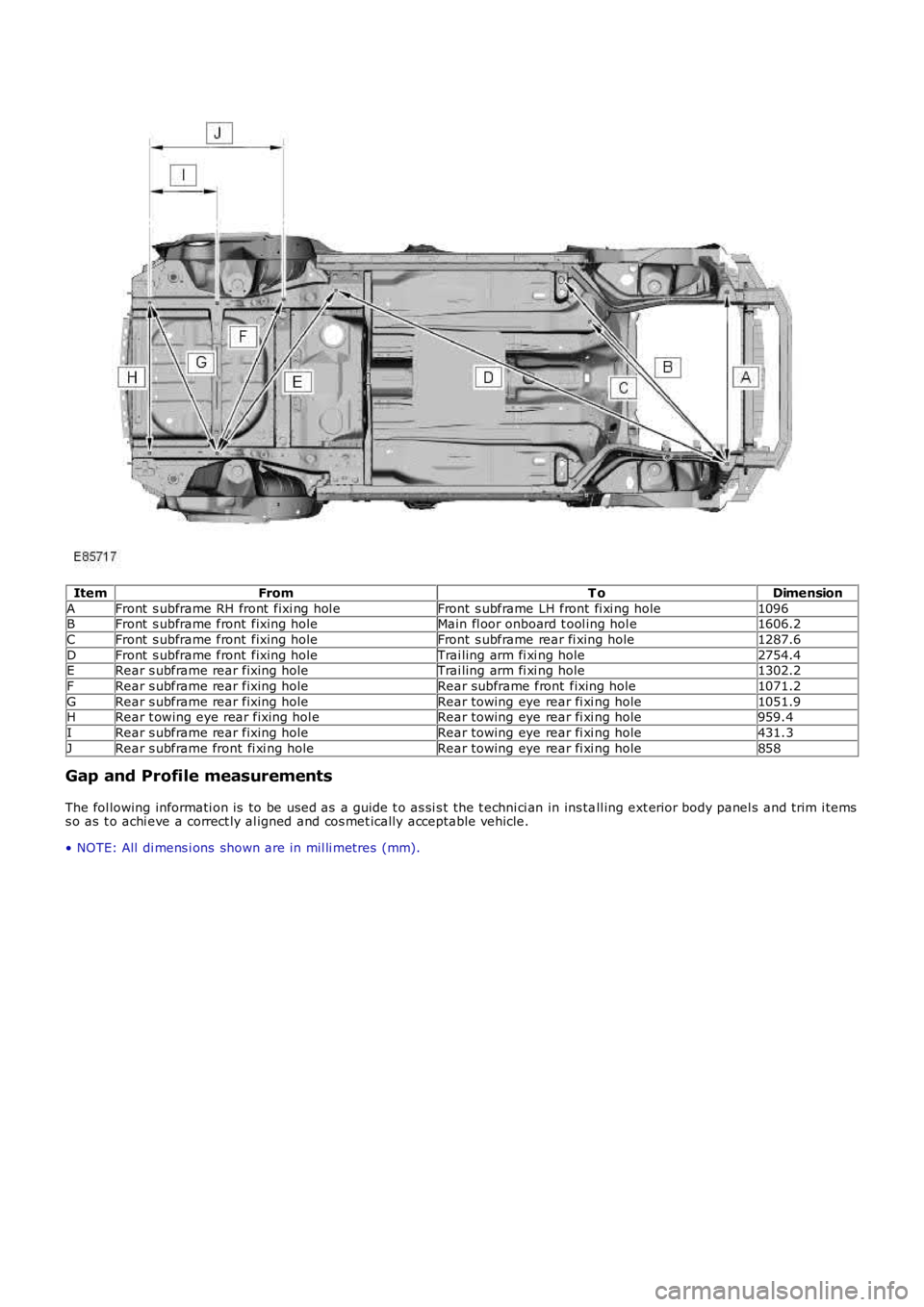
ItemFromT oDimension
AFront s ubframe RH front fixi ng hol eFront s ubframe LH front fi xi ng hole1096BFront s ubframe front fixing holeMain fl oor onboard t ool ing hol e1606.2
CFront s ubframe front fixing holeFront s ubframe rear fi xing hole1287.6
DFront s ubframe front fixing holeTrai ling arm fi xi ng hole2754.4ERear s ubframe rear fixing holeTrai ling arm fi xi ng hole1302.2
FRear s ubframe rear fixing holeRear subframe front fixing hole1071.2
GRear s ubframe rear fixing holeRear towing eye rear fi xi ng hole1051.9HRear t owing eye rear fixing hol eRear towing eye rear fi xi ng hole959.4
IRear s ubframe rear fixing holeRear towing eye rear fi xi ng hole431.3
JRear s ubframe front fi xi ng holeRear towing eye rear fi xi ng hole858
Gap and Profile measurements
The fol lowing informati on is to be used as a guide t o as si s t the t echni ci an in ins tall ing ext erior body panel s and trim i temss o as t o achi eve a correct ly al igned and cos met ically acceptable vehicle.
• NOTE: All di mens i ons shown are in mil li metres (mm).
Page 2709 of 3229
Publ is hed: 11-May-2011
Uni-Body, Subframe and Mounting System - Rear Subframe
Removal and Installation
General Equipment
P o we rt ra i n Ja ck
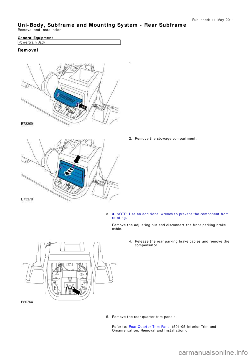
Removal
1.
Remove the stowage compartment. 2.
3. NOTE: Use an additional wrench to prevent the component from
ro t a t i ng .
Remove t he adjus t i ng nut and di s connect t he front parki ng brake
cabl e . 3.
Release the rear parking brake cables and remove the
compens at or. 4.
Remove the rear quarter trim panels.
Refer to: Rear Quarter Trim Panel
(501-05 Int eri or Tri m and
Ornament at i on, Removal and Ins t al lat i on). 5.
Page 2724 of 3229

Contents
4
L
Climate control
AIR VENTS ................................................... 101
MANUAL CLIMATE CONTROL ...................... 102
AUTOMATIC CLIMATE CONTROL ................. 103
HEATED WINDOWS AND MIRRORS ............ 104
AUXILIARY HEATER ..................................... 104
ELECTRIC SUNROOF .................................... 105
Convenience features
SUN VISORS ................................................ 107
CLOCK .......................................................... 107
CIGAR LIGHTER ........................................... 109
ASHTRAY ..................................................... 109
AUXILIARY POWER SOCKETS ..................... 110
CUP HOLDERS ............................................. 111
STORAGE COMPARTMENTS ........................ 112
Starting the engine
GENERAL INFORMATION ............................. 113
STARTING A PETROL ENGINE ..................... 114
STARTING A DIESEL ENGINE ....................... 115
DIESEL PARTICULATE FILTER (DPF) ........... 116
Transmission
MANUAL TRANSMISSION ............................ 118
AUTOMATIC TRANSMISSION ...................... 118
TECHNICAL SPECIFICATIONS ...................... 122
Brakes
PRINCIPLE OF OPERATION .......................... 123
HINTS ON DRIVING WITH ABS .................... 123
PARKING BRAKE .......................................... 124
Parking aid
PRINCIPLE OF OPERATION .......................... 126
USING THE PARKING AID ............................ 127
Driving hints
GENERAL DRIVING POINTS ......................... 128
REDUCED ENGINE PERFORMANCE ............. 128
RUNNING-IN ................................................ 128
ECONOMICAL DRIVING ................................ 129
Cruise control
PRINCIPLE OF OPERATION .......................... 130
USING CRUISE CONTROL ............................ 130
Terrain response
PRINCIPLE OF OPERATION .......................... 132
USING TERRAIN RESPONSE ........................ 132
Hill descent control (HDC)
PRINCIPLE OF OPERATION .......................... 136
USING HDC ................................................... 137
Traction control
USING TRACTION CONTROL ........................ 139
Stability control
PRINCIPLE OF OPERATION .......................... 140
USING STABILITY CONTROL ........................ 141
Fuel and refuelling
SAFETY PRECAUTIONS................................. 142
FUEL QUALITY .............................................. 142
RUNNING OUT OF FUEL................................ 144
FUEL CUT-OFF............................................... 144
FUEL FILLER FLAP ........................................ 144
REFUELLING ................................................. 145
TECHNICAL SPECIFICATIONS ....................... 146
Load carrying
GENERAL INFORMATION.............................. 147
LUGGAGE ANCHOR POINTS ......................... 148
LUGGAGE COVERS ....................................... 149
Towing
TOWING A TRAILER...................................... 150
LEVELLING.................................................... 151
ESSENTIAL TOWING CHECKS ...................... 151
RECOMMENDED TOWING WEIGHTS ............ 152
TOW BAR ...................................................... 153
Vehicle care
CLEANING THE ALLOY WHEELS................... 154
CLEANING THE EXTERIOR ............................ 154
CLEANING THE INTERIOR ............................ 155
REPAIRING MINOR PAINT DAMAGE ............ 156
Maintenance
GENERAL INFORMATION.............................. 157
OPENING AND CLOSING THE BONNET......... 160
ENGINE COMPARTMENT OVERVIEW ........... 161
ENGINE OIL CHECK....................................... 162
Page 2725 of 3229

Contents
5
R
ENGINE COOLANT CHECK ............................ 163
BRAKE AND CLUTCH FLUID CHECK ............. 165
POWER STEERING FLUID CHECK ................ 166
WASHER FLUID CHECK ................................ 167
TECHNICAL SPECIFICATIONS ...................... 169
Vehicle battery
BATTERY WARNING SYMBOLS ................... 171
BATTERY CARE ............................................ 171
USING BOOSTER CABLES ............................ 173
CHARGING THE VE HICLE BATTERY ............. 174
CHANGING THE VE HICLE BATTERY ............. 174
Wheels and tyres
GENERAL INFORMATION ............................. 176
TYRE CARE ................................................... 177
USING WINTER TYRES................................. 183
CHANGING A ROAD WHEEL ......................... 183
TYRE REPAIR KIT ......................................... 187
USING SNOW CHAINS.................................. 192
TYRE GLOSSARY.......................................... 193
TECHNICAL SPECIFICATIONS ...................... 194
Fuses
FUSE BOX LOCATIONS ................................. 195
CHANGING A FUSE ....................................... 195
FUSE SPECIFICATION CHART....................... 196
Emergency equipment
HAZARD WARNING FLASHERS .................... 204
WARNING TRIANGLE ................................... 204
Status after a collision
DRIVING AFTER A COLLISION...................... 205
INSPECTING SAFETY SYSTEM COMPONENTS ...
206
Vehicle recovery
TOWING POINTS .......................................... 207
LASHING POINTS ......................................... 208
TRANSPORTING THE VEHICLE..................... 208
TOWING THE VEHICLE ON FOUR WHEELS .. 208
Vehicle identification
VEHICLE IDENTIFICATION PLATE................. 210
VEHICLE IDENTIFI CATION NUMBER (VIN) ... 210
VEHICLE BUILD DATE PLATE ....................... 210
Technical specifications
ENGINE SPECIFICATIONS ............................ 211
WEIGHTS...................................................... 212
DIMENSIONS................................................ 213
Type approval
Declarations of conformity ........................... 215
Audio introduction
RADIO RECEPTION....................................... 218
Audio unit overview
AUDIO UNIT OVERVIEW............................... 219
Audio unit operation
ON OR OFF CONTROL .................................. 223
VOLUME CONTROL ...................................... 223
AUDIO CONTROL ......................................... 223
WAVEBAND BUTTON ................................... 224
AUTOSTORE CONTROL ................................ 225
STATION PRESET BUTTONS ........................ 226
TRAFFIC INFORMATION CONTROL .............. 226
Audio unit menus
RADIO DATA SYSTEM (RDS) ....................... 228
REGIONAL MODE (REG) .............................. 228
ENHANCED OTHER NETWORK (RDS-EON).. 229
ALTERNATIVE FREQUENCIES ...................... 229
NEWS BROADCASTS ................................... 230
PRIORITY PROGRAMME TYPE (PTY) .......... 231
RESETTING THE AUDIO UNIT ...................... 233
Digital audio broadcasting
GENERAL INFORMATION ............................. 234
AUDIO CONTROLS ....................................... 235
DISPLAY OPTIONS ....................................... 236
CHANNEL AUTOMATIC TUNING................... 236
CHANNEL OPTIONS ..................................... 236
PRESET BUTTONS ....................................... 238
SETTINGS..................................................... 240
Compact disc player
LOADING COMPACT DISCS ......................... 245
EJECTING COMPACT DISCS ........................ 246
EJECTING MULTIPLE CO MPACT DISCS....... 246
COMPACT DISC SELECTION ........................ 246
COMPACT DISC PLAYBACK ......................... 246
Page 2731 of 3229
11
Quick start
R
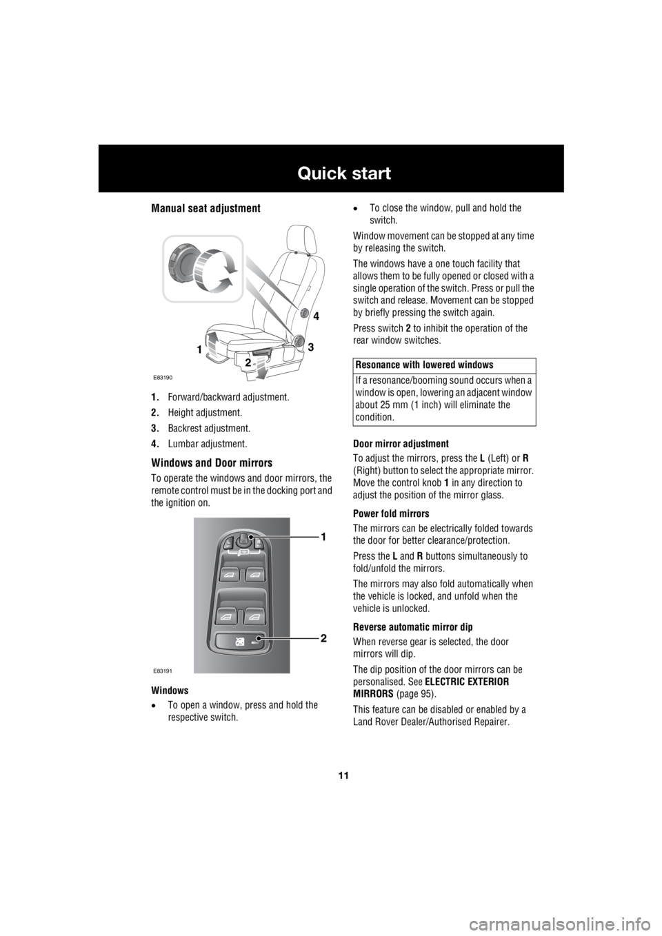
Manual seat adjustment
1. Forward/backward adjustment.
2. Height adjustment.
3. Backrest adjustment.
4. Lumbar adjustment.
Windows and Door mirrors
To operate the windows and door mirrors, the
remote control must be in the docking port and
the ignition on.
Windows
• To open a window, press and hold the
respective switch. •
To close the window, pull and hold the
switch.
Window movement can be stopped at any time
by releasing the switch.
The windows have a one touch facility that
allows them to be fully opened or closed with a
single operation of the switch. Press or pull the
switch and release. Mo vement can be stopped
by briefly pressing the switch again.
Press switch 2 to inhibit the operation of the
rear window switches.
Door mirror adjustment
To adjust the mirrors, press the L (Left) or R
(Right) button to select the appropriate mirror.
Move the control knob 1 in any direction to
adjust the position of the mirror glass.
Power fold mirrors
The mirrors can be electr ically folded towards
the door for better clearance/protection.
Press the L and R buttons simultaneously to
fold/unfold the mirrors.
The mirrors may also fold automatically when
the vehicle is locked, and unfold when the
vehicle is unlocked.
Reverse automatic mirror dip
When reverse gear is selected, the door
mirrors will dip.
The dip position of the door mirrors can be
personalised. See ELECTRIC EXTERIOR
MIRRORS (page 95).
This feature can be disabled or enabled by a
Land Rover Dealer/A uthorised Repairer.
3
2
1
E83190
4
1
2
E83191
Resonance with lowered windows
If a resonance/booming sound occurs when a
window is open, lowering an adjacent window
about 25 mm (1 inch) will eliminate the
condition.
Page 2741 of 3229
21
Quick start
R
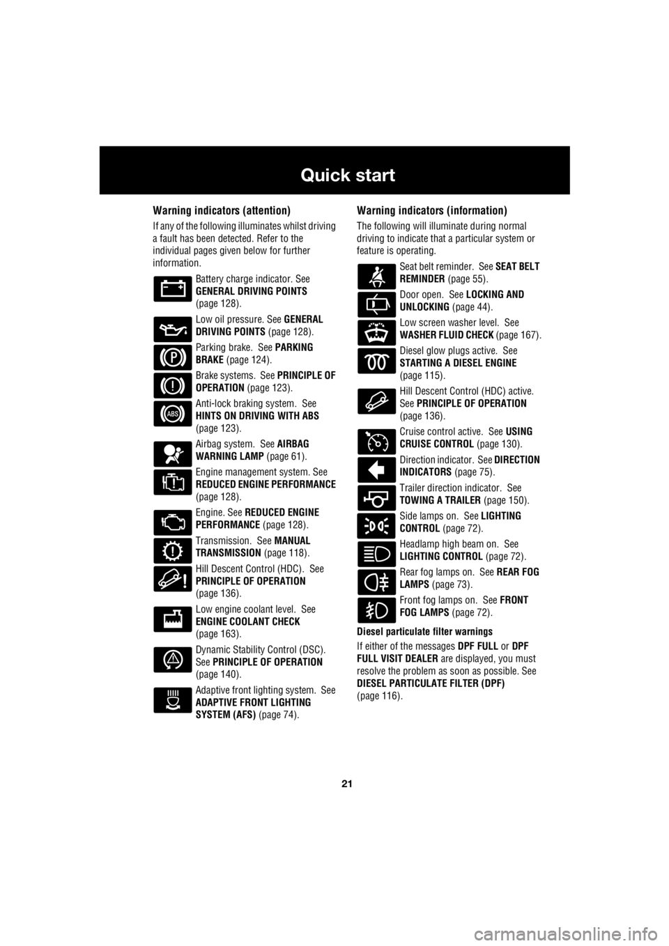
Warning indicators (attention)
If any of the following illuminates whilst driving
a fault has been detected. Refer to the
individual pages give n below for further
information.
Battery charge indicator. See
GENERAL DRIVING POINTS
(page 128).
Low oil pressure. See GENERAL
DRIVING POINTS (page 128).
Parking brake. See PARKING
BRAKE (page 124).
Brake systems. See PRINCIPLE OF
OPERATION (page 123).
Anti-lock braking system. See
HINTS ON DRIVING WITH ABS
(page 123).
Airbag system. See AIRBAG
WARNING LAMP (page 61).
Engine management system. See
REDUCED ENGINE PERFORMANCE
(page 128).
Engine. See REDUCED ENGINE
PERFORMANCE (page 128).
Transmission. See MANUAL
TRANSMISSION (page 118).
Hill Descent Control (HDC). See
PRINCIPLE OF OPERATION
(page 136).
Low engine coolant level. See
ENGINE COOLANT CHECK
(page 163).
Dynamic Stability Control (DSC).
See PRINCIPLE OF OPERATION
(page 140).
Adaptive front lighting system. See
ADAPTIVE FRONT LIGHTING
SYSTEM (AFS) (page 74).
Warning indicators (information)
The following will illuminate during normal
driving to indicate that a particular system or
feature is operating.
Seat belt reminder. See SEAT BELT
REMINDER (page 55).
Door open. See LOCKING AND
UNLOCKING (page 44).
Low screen washer level. See
WASHER FLUID CHECK (page 167).
Diesel glow plugs active. See
STARTING A DIESEL ENGINE
(page 115).
Hill Descent Control (HDC) active.
See PRINCIPLE OF OPERATION
(page 136).
Cruise control active. See USING
CRUISE CONTROL (page 130).
Direction indicator. See DIRECTION
INDICATORS (page 75).
Trailer direction indicator. See
TOWING A TRAILER (page 150).
Side lamps on. See LIGHTING
CONTROL (page 72).
Headlamp high beam on. See
LIGHTING CONTROL (page 72).
Rear fog lamps on. See REAR FOG
LAMPS (page 73).
Front fog lamps on. See FRONT
FOG LAMPS (page 72).
Diesel particulate filter warnings
If either of the messages DPF FULL or DPF
FULL VISIT DEALER are displayed, you must
resolve the problem as soon as possible. See
DIESEL PARTICULATE FILTER (DPF)
(page 116).
Page 2743 of 3229
23
Quick start
R
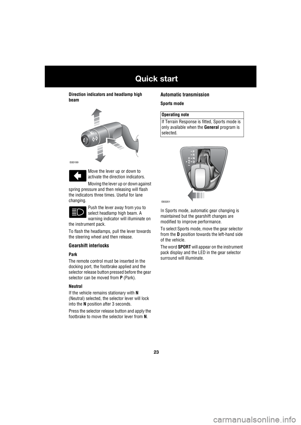
Direction indicators and headlamp high
beam
Move the lever up or down to
activate the direction indicators.
Moving the lever up or down against
spring pressure and then releasing will flash
the indicators three times. Useful for lane
changing.
Push the lever away from you to
select headlamp high beam. A
warning indicator will illuminate on
the instrument pack.
To flash the headlamps, pull the lever towards
the steering wheel and then release.
Gearshift interlocks
Park
The remote control must be inserted in the
docking port, the footbrake applied and the
selector release button pr essed before the gear
selector can be moved from P (Park).
Neutral
If the vehicle remains stationary with N
(Neutral) selected, the selector lever will lock
into the N position after 3 seconds.
Press the selector rele ase button and apply the
footbrake to move the selector lever from N.
Automatic transmission
Sports mode
In Sports mode, automatic gear changing is
maintained but the gearshift changes are
modified to improve performance.
To select Sports mode, move the gear selector
from the D position towards the left-hand side
of the vehicle.
The word SPORT will appear on the instrument
pack display and the LED in the gear selector
surround will illuminate.
E83199
Operating note
If Terrain Response is fi tted, Sports mode is
only available when the General program is
selected.
E83201
Page 2755 of 3229
35
Introduction
R
IntroductionSYMBOLS GLOSSARY
Warnings
Cautions
Symbols
This recycling symbol identifies
those items that mu st be disposed
of safely in order to prevent
unnecessary damage to the environment.
This symbol identifies those
features that can be adjusted,
disabled or enabled by a Land
Rover Dealer/Authorised Repairer.
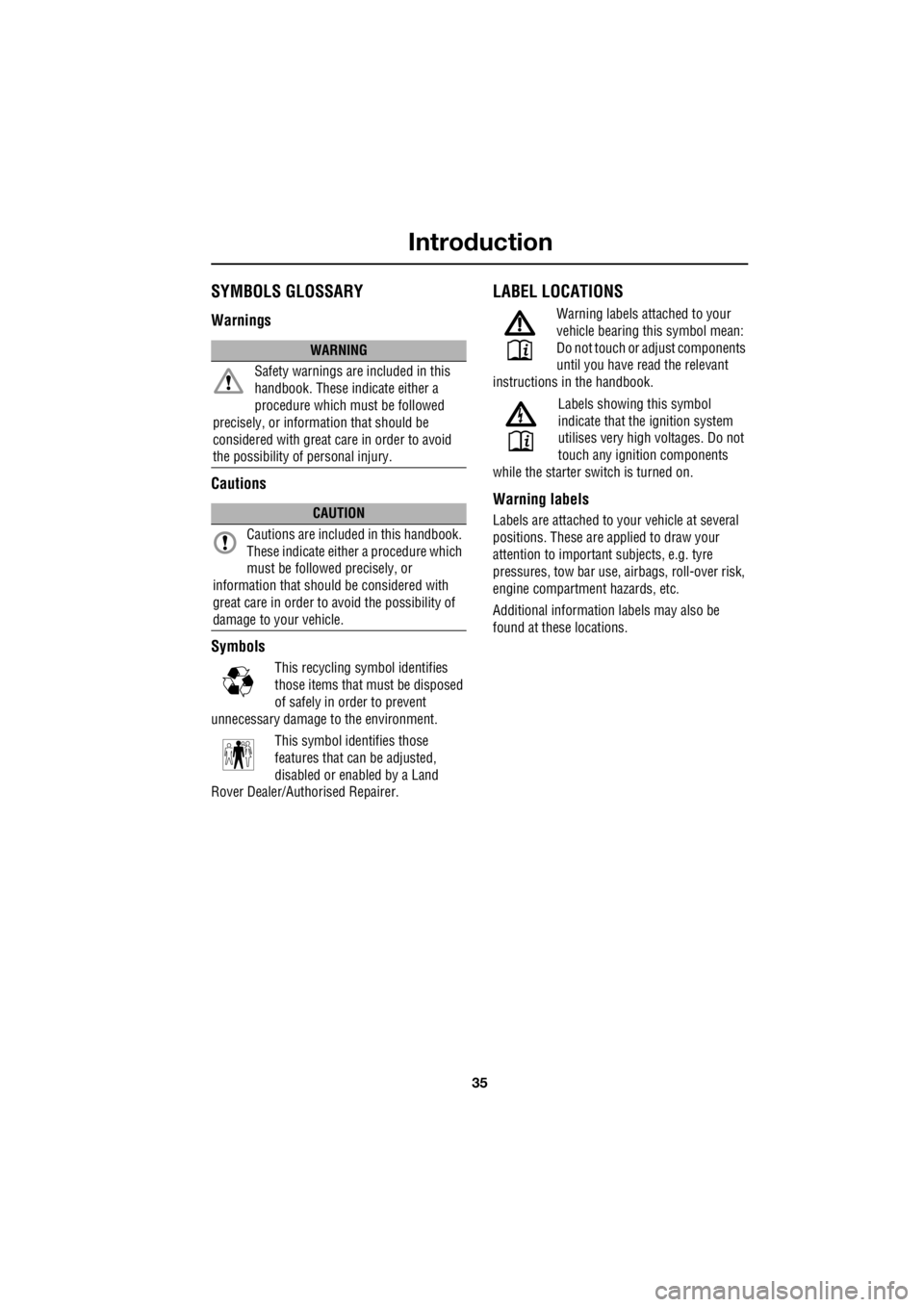
LABEL LOCATIONS
Warning labels attached to your
vehicle bearing this symbol mean:
Do not touch or adjust components
until you have re ad the relevant
instructions in the handbook.
Labels showing this symbol
indicate that the ignition system
utilises very high voltages. Do not
touch any ignition components
while the starter switch is turned on.
Warning labels
Labels are attached to your vehicle at several
positions. These are ap plied to draw your
attention to important subjects, e.g. tyre
pressures, tow bar use, airbags, roll-over risk,
engine compartment hazards, etc.
Additional information labels may also be
found at these locations.
WARNING
Safety warnings ar e included in this
handbook. These indicate either a
procedure which must be followed
precisely, or information that should be
considered with great care in order to avoid
the possibility of personal injury.
CAUTION
Cautions are included in this handbook.
These indicate either a procedure which
must be followed precisely, or
information that should be considered with
great care in order to avoid the possibility of
damage to your vehicle.
E83651
E83652