2006 LAND ROVER FRELANDER 2 tow
[x] Cancel search: towPage 2906 of 3229
Wheels and tyres
186
L
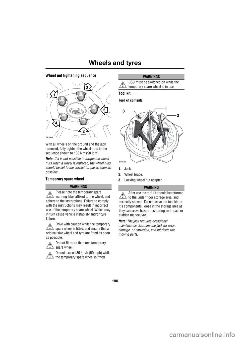
Wheel nut tightening sequence
With all wheels on the ground and the jack
removed, fully tighten the wheel nuts in the
sequence shown to 133 Nm (98 lb.ft).
Note: If it is not possible to torque the wheel
nuts when a wheel is replaced, the wheel nuts
should be set to the correct torque as soon as
possible.
Temporary spare wheel Tool kit
Tool kit contents
1.
Jack.
2. Wheel brace.
3. Locking wheel nut adapter.
Note: The jack requi res occasional
maintenance. Examine the jack for wear,
damage, or corrosion, and lubricate the
moving parts.
WARNINGS
Please note the temporary spare
warning label affixed to the wheel, and
adhere to the instructions. Failure to comply
with the instructions may result in incorrect
use of the temporary spare wheel. Which may
in turn cause vehicle instability and/or tyre
failure.
Drive with caution while the temporary
spare wheel is fitted, and ensure that an
original size wheel and tyre are fitted as soon
as possible.
Do not fit more than one temporary
spare wheel.
Do not exceed 80 km/h (50 mph) while
the temporary spare wheel is fitted.
E83968
5
1
3
2
4
DSC must be switched on while the
temporary spare wheel is in use.
WARNING
After use the tool kit should be returned
to the under floor storage area, and
correctly stowed. Do not leave the tool kit, or
it's components, loose in the storage area as
they can prove hazardous during an impact or
sudden manoeuvre.
WARNINGS
3
E80162
1
2
Page 2913 of 3229

193
Wheels and tyres
R
• Avoid tyre/vehicle damage by removing
the traction devices as soon as the
conditions allow.
TYRE GLOSSARY
Terms used
lbf/in² or psi
Pounds per square inch, an imperial unit of
measure for pressure.
kPa
Kilo Pascal, a metric unit of measure for
pressure.
Cold tyre pressure
The air pressure in a tyre which has been
standing in excess of th ree hours, or driven for
less than one mile.
Maximum inflation pressure
The maximum pressure to which the tyre
should be inflated. This pressure is given on
the tyre side wall in lbf/in² (psi) and kPa.
Note: This pressure is the maximum allowed
by the tyre manufacturer. It is not the pressure
recommended for use. See TECHNICAL
SPECIFICATIONS (page 194).
Kerb weight
The weight of a standa rd vehicle, including a
full tank of fuel, any optional equipment fitted,
and with the correct coolant and oil levels.
Gross vehicle weight
The maximum permissible weight of a vehicle
with driver, passengers, load, luggage,
equipment, and towbar load.
Accessory weight
The combined weight (in excess of those items
replaced) of items available as factory installed
equipment. Production options weight
The combined weight of options installed
which weigh in excess of 1.4 kg (3 lb) more
than the standard items that they replaced, and
are not already considered in kerb or accessory
weights. Items such as heavy duty brakes, high
capacity battery, special trim etc.
Vehicle capacity weight
The number of seats multiplied by 68 kg (150
lb) plus the rated amount of load/luggage.
Maximum loaded vehicle weight
The sum of kerb wei ght, accessory weight,
vehicle capacity weig ht, plus any production
option weights.
Rim
The metal support for a ty re, or tyre and tube,
upon which the tyre beads are seated.
Bead
The inner edge of a tyre th at is shaped to fit to
the rim and form an air tight seal. The bead is
constructed of steel wires which are wrapped,
or reinforced, by the ply cords.
Page 2927 of 3229
207
Vehicle recovery
R
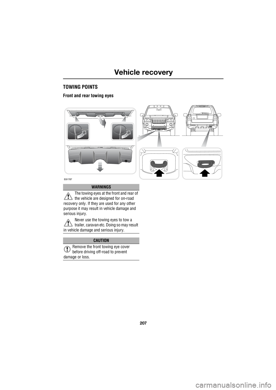
Vehicle recoveryTOWING POINTS
Front and rear towing eyes
E81787
WARNINGS
The towing eyes at the front and rear of
the vehicle are designed for on-road
recovery only. If they are used for any other
purpose it may result in vehicle damage and
serious injury.
Never use the towing eyes to tow a
trailer, caravan etc. Doing so may result
in vehicle damage and serious injury.
CAUTION
Remove the front towing eye cover
before driving off-road to prevent
damage or loss.
Page 2928 of 3229
Vehicle recovery
208
L
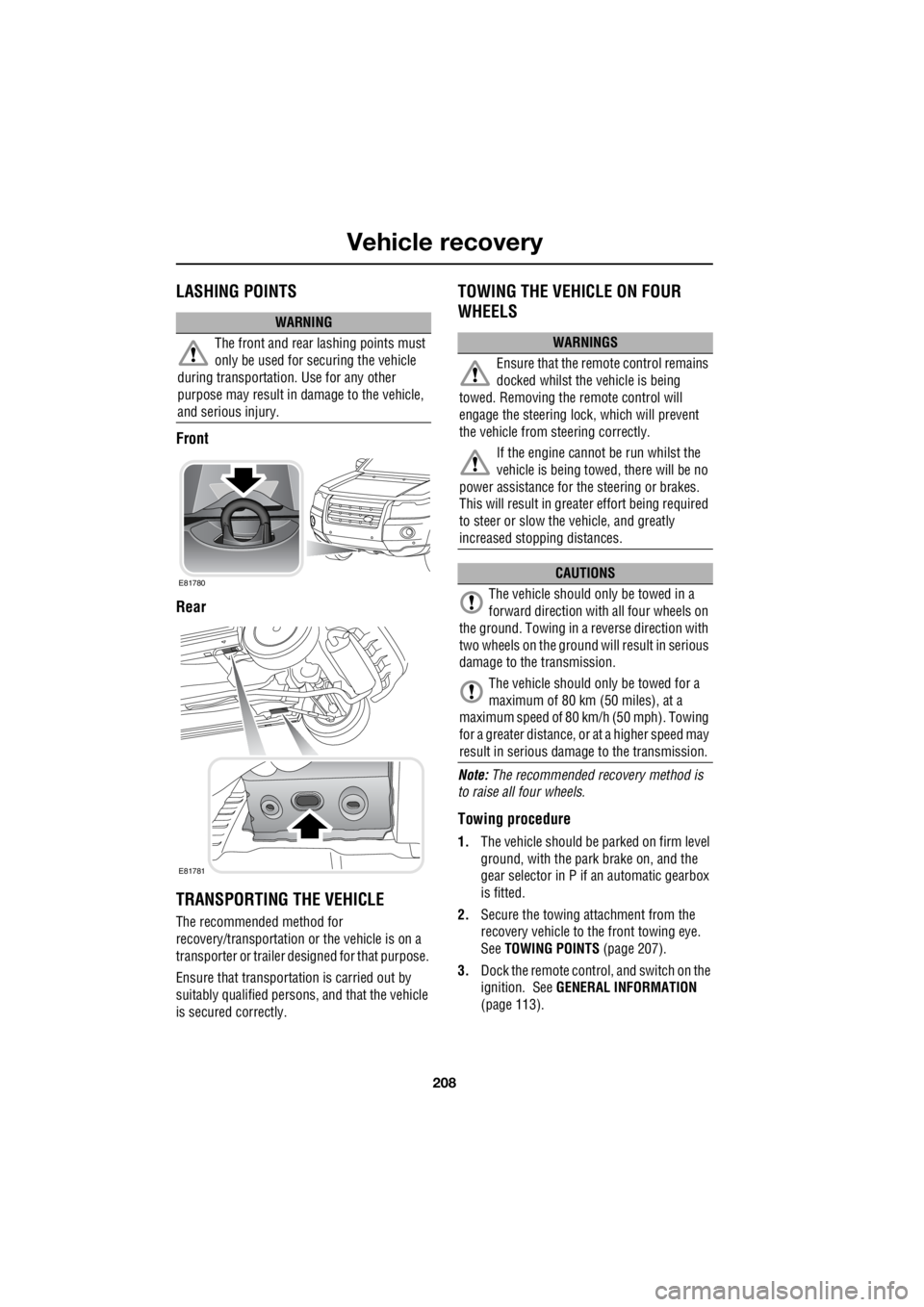
LASHING POINTS
Front
Rear
TRANSPORTING THE VEHICLE
The recommended method for
recovery/transportation or the vehicle is on a
transporter or trailer de signed for that purpose.
Ensure that transporta tion is carried out by
suitably qualified persons , and that the vehicle
is secured correctly.
TOWING THE VEHICLE ON FOUR
WHEELS
Note: The recommended recovery method is
to raise all four wheels.
Towing procedure
1. The vehicle should be parked on firm level
ground, with the park brake on, and the
gear selector in P if an automatic gearbox
is fitted.
2. Secure the towing attachment from the
recovery vehicle to the front towing eye.
See TOWING POINTS (page 207).
3. Dock the remote control, and switch on the
ignition. See GENERAL INFORMATION
(page 113).
WARNING
The front and rear lashing points must
only be used for securing the vehicle
during transportation. Use for any other
purpose may result in da mage to the vehicle,
and serious injury.
E81780
E81781
WARNINGS
Ensure that the remote control remains
docked whilst the vehicle is being
towed. Removing the remote control will
engage the steering lo ck, which will prevent
the vehicle from steering correctly.
If the engine cannot be run whilst the
vehicle is being towed, there will be no
power assistance for the steering or brakes.
This will result in grea ter effort being required
to steer or slow the vehicle, and greatly
increased stopping distances.
CAUTIONS
The vehicle should only be towed in a
forward direction with all four wheels on
the ground. Towing in a reverse direction with
two wheels on the ground will result in serious
damage to the transmission.
The vehicle should only be towed for a
maximum of 80 km (50 miles), at a
maximum speed of 80 k m/h (50 mph). Towing
for a greater distance, or at a higher speed may
result in serious dama ge to the transmission.
Page 2929 of 3229

209
Vehicle recovery
R
4. Apply the foot brake, and select neutral.
5. With the footbrake still applied, release the
park brake.
6. The vehicle can now be towed a maximum
of 80 km (50 miles) at a maximum speed
of 80 kmh (50 mph).
7. Upon arrival at the destination, ensure
wherever possible that the vehicle is
parked on firm level ground.
8. Apply the park brake, and place the
selector lever into the P (park) position.
9. Switch off the ignition, and remove the
remote control.
10. Remove the towing attachment from the
towing eye.
CAUTION
Leaving the ignition switched on for
extended periods will ca use the battery to
drain.
WARNING
Use extreme caution when detaching
towing equipment. Vehicle movement
is possible which can resu lt in serious injuries.
Page 2933 of 3229
213
Technical specifications
R
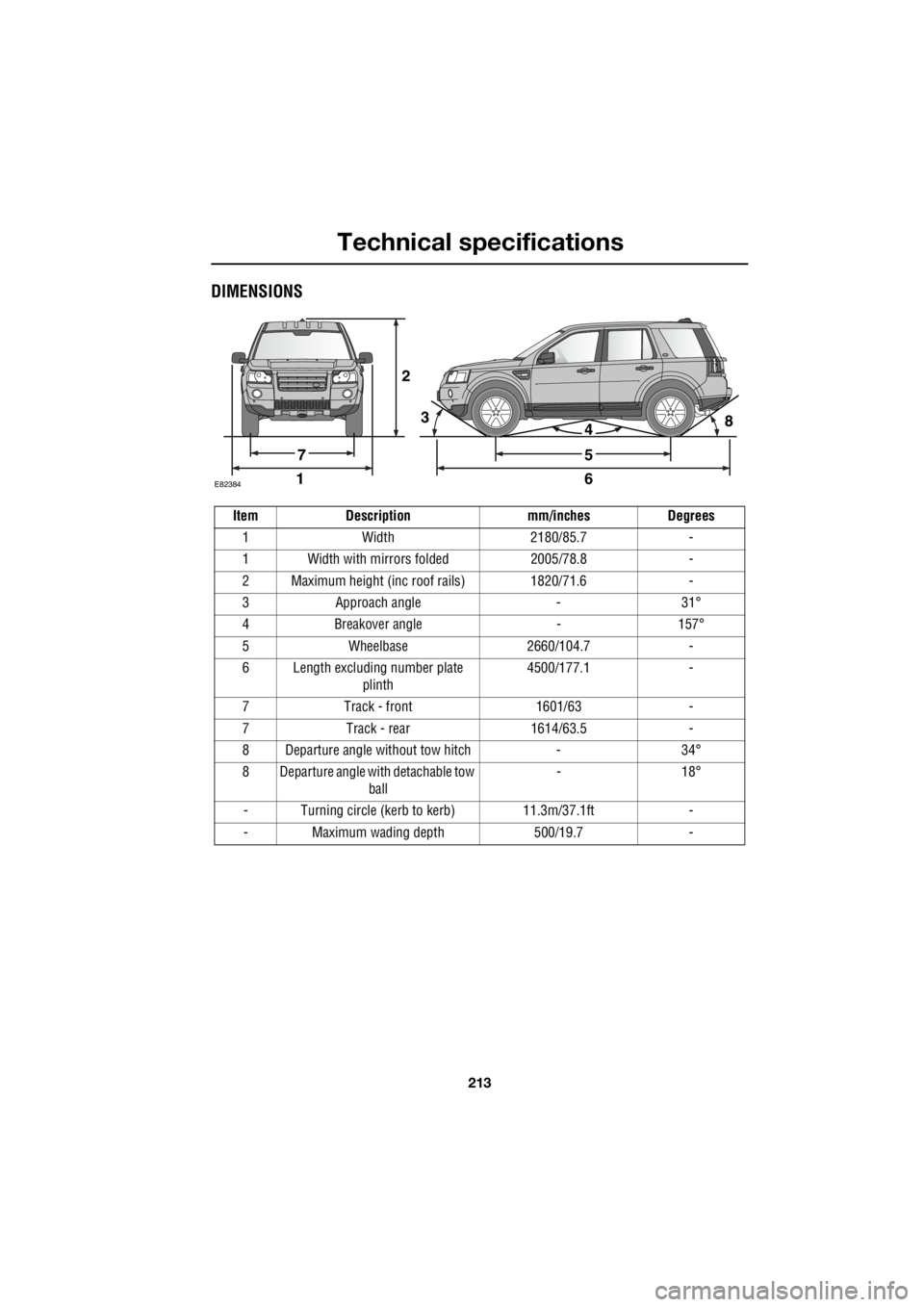
DIMENSIONS
2
E8238416
5
438
7
Item Description mm/inches Degrees 1 Width 2180/85.7 -
1 Width with mirrors folded 2005/78.8 -
2 Maximum height (inc roof rails) 1820/71.6 -
3 Approach angle - 31°
4 Breakover angle - 157°
5 Wheelbase 2660/104.7 -
6 Length excluding number plate plinth 4500/177.1 -
7 Track - front 1601/63 -
7 Track - rear 1614/63.5 -
8 Departure angle without tow hitch - 34°
8 Departure angle with detachable tow ball - 18°
- Turning circle (kerb to kerb) 11.3m/37.1ft -
- Maximum wading depth 500/19.7 -
Page 2974 of 3229

Telephone
254
L
TelephoneGENERAL INFORMATION
Note: The vehicle tele phone system is
designed to function with a wide variety of
Bluetooth telephones. As these telephones
have a wide range of audio and echo
performance characteristics, it may take a few
seconds for the vehicl e telephone system to
adapt and deliver optimum audio performance.
It may be necessary to reduce the in-vehicle
volume slightly to fully optimise audio
performance and reduce echo. Note:
The vehicle's Bluetooth telephone
system can be used with an appropriate
Bluetooth-equipped mobile telephone.
Note: Please refer to your Land Rover
Dealer/Authorised Repairer for a list of
compatible telephones.
Telephone networks
The Telephone netw ork standard allows you to
use your telephone in many countries.
However, telephone reception may be poor or
unavailable in remote re gions. This may be due
to the inadequate power of the transmitter,
which results in a weak signal or incomplete
coverage.
WARNINGS
Using the telephone ne ar the car: do not
telephone inside a garage or near an
open car bonnet. The air may contain fuel
vapours and the tele phone could produce
sparks and start a fire.
Unusual ambient conditions: Switch off
the telephone in areas where high
explosives are being used. High frequency
remote controls could be interfered with and
cause an explosion. Switch off your telephone
in areas with a high explosion risk. This
includes filling stations, fuel storage areas or
chemical factories, as well as places where the
air contains fuel vapour, chemicals or metal
dust. The telephone might possibly produce
sparks and cause a fire or explosion.
Medical equipment: The functioning of
cardiac pacemakers or hearing aids
may be impaired when the phone is in use.
Check with a doctor or manufacturer whether
any such devices you or your passengers are
using are sufficiently protected against
high-frequency energy.
Always stow your mobile phone
securely. In an accident loose items can
cause injury.
Page 2976 of 3229
Telephone
256
L
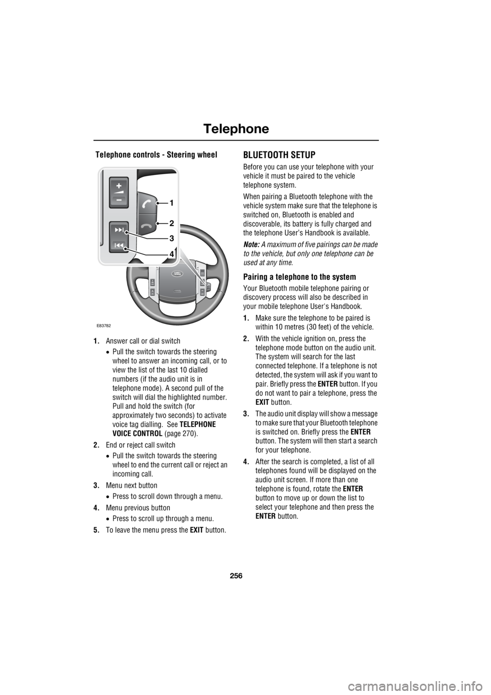
Telephone controls - Steering wheel
1. Answer call or dial switch
• Pull the switch towards the steering
wheel to answer an incoming call, or to
view the list of the last 10 dialled
numbers (if the audio unit is in
telephone mode). A second pull of the
switch will dial th e highlighted number.
Pull and hold the switch (for
approximately two seconds) to activate
voice tag dialling. See TELEPHONE
VOICE CONTROL (page 270).
2. End or reject call switch
• Pull the switch towards the steering
wheel to end the current call or reject an
incoming call.
3. Menu next button
• Press to scroll down through a menu.
4. Menu previous button
• Press to scroll up through a menu.
5. To leave the menu press the EXIT button.
BLUETOOTH SETUP
Before you can use your telephone with your
vehicle it must be paired to the vehicle
telephone system.
When pairing a Bluet ooth telephone with the
vehicle system ma ke sure that the telephone is
switched on, Bluetooth is enabled and
discoverable, its battery is fully charged and
the telephone User’s Handbook is available.
Note: A maximum of five pairings can be made
to the vehicle, but only one telephone can be
used at any time.
Pairing a telephone to the system
Your Bluetooth mobile telephone pairing or
discovery process will al so be described in
your mobile telephone User's Handbook.
1. Make sure the telephone to be paired is
within 10 metres (30 feet) of the vehicle.
2. With the vehicle ignition on, press the
telephone mode button on the audio unit.
The system will search for the last
connected tele phone. If a telephone is not
detected, the system w ill ask if you want to
pair. Briefly press the ENTER button. If you
do not want to pair a telephone, press the
EXIT button.
3. The audio unit display will show a message
to make sure that yo ur Bluetooth telephone
is switched on. Briefly press the ENTER
button. The system will then start a search
for your telephone.
4. After the search is completed, a list of all
telephones found will be displayed on the
audio unit screen. If more than one
telephone is found, rotate the ENTER
button to move up or down the list to
select your telephone and then press the
ENTER button.
4
3
2
1
E83782