2006 LAND ROVER FRELANDER 2 power steering
[x] Cancel search: power steeringPage 560 of 3229
Publi s hed: 11-May-2011
Power Steering - Steering Gear
Removal and Inst all ati on
Removal
1. W ARNING: Make sure t o s upport the vehicle wit h axle
s tands .
Rais e and s upport t he vehi cl e.
1.
Remove t he front road wheels and t ires.
Refer t o: W heel and Ti re (204-04 W heel s and Tires, Removal and
Inst all at ion).
2.
Remove t he front subframe as s embly.
Refer t o: Front Subframe (502-00 Uni -Body, Subframe and Mount ing
Syst em, Removal and Ins tall ati on).
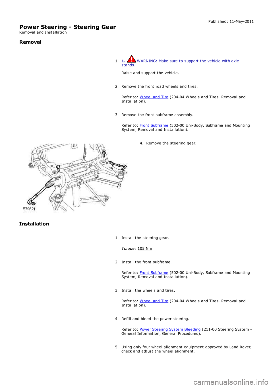
3. Remove t he s teeri ng gear.
4.
Installation Inst all t he s teeri ng gear.
T orque: 105 Nm 1.
Inst all t he front subframe.
Refer t o: Front Subframe (502-00 Uni -Body, Subframe and Mount ing
Syst em, Removal and Ins tall ati on).
2.
Inst all t he wheel s and t ires .
Refer t o: W heel and Ti re (204-04 W heel s and Tires, Removal and
Inst all at ion).
3.
Refi ll and bleed t he power st eeri ng.
Refer t o: Power St eering Sys tem Bleeding (211-00 St eering Sys tem -
General Informat ion, General Procedures ).
4.
Us ing onl y four wheel al ignment equi pment approved by Land Rover,
check and adjus t t he wheel al ignment.
5.
Page 561 of 3229
Publi s hed: 11-May-2011
Power Steering - Power Steering Fluid Cooler
Removal and Inst all ati on
Removal
1. W ARNING: Do not work on or under a vehi cle s upported onl yby a jack. Al ways support t he vehi cl e on s afet y s tands .
Rais e and s upport t he vehi cl e.
1.
Remove t he front wheel s and ti res .
Refer t o: W heel and Ti re (204-04 W heel s and Tires, Removal andInst all at ion).
2.
Remove t he front bumper.
Refer t o: Front Bumper (501-19 Bumpers , Removal and Ins tall ati on).
3.
Remove t he RH headlamp as s embly.
Refer t o: Headl amp As sembl y (417-01 Ext eri or Li ght ing, Removaland Inst all at ion).
4.
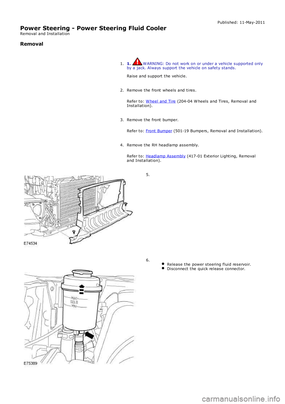
5.
Releas e t he power s t eering flui d res ervoir.Di sconnect t he qui ck rel eas e connect or.
6.
Page 563 of 3229
Publi s hed: 11-May-2011
Power Steering - Power Steering Fluid Reservoir
Removal and Inst all ati on
Removal
Remove t he power s t eering flui d res ervoir cap.1.
Us ing a s ui table s yringe, remove t he power st eering fl ui d from thepower st eeri ng fl uid reservoi r.2.
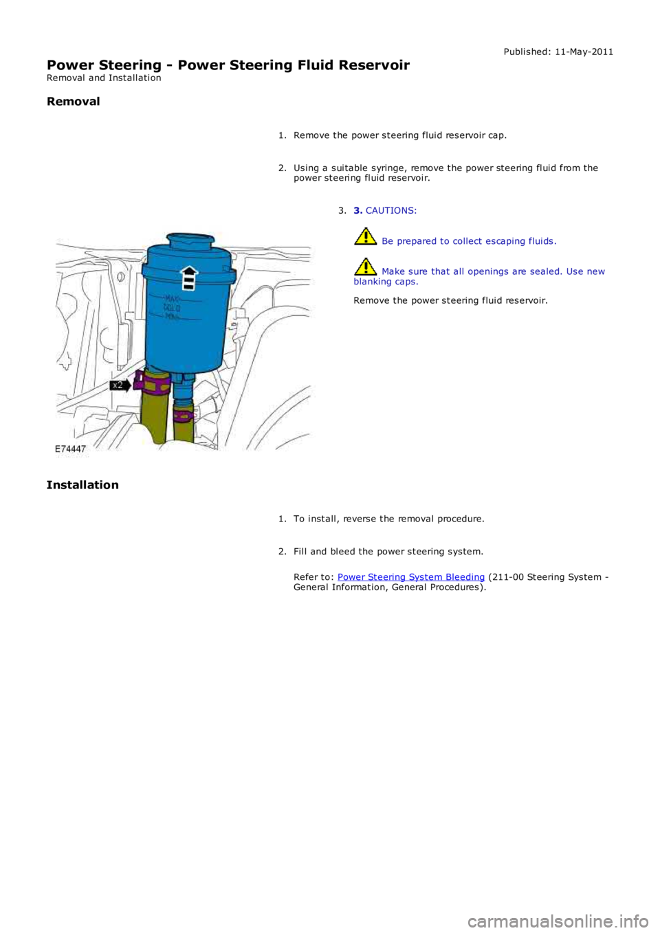
3. CAUTIONS:
Be prepared t o collect es caping flui ds .
Make s ure that all openings are sealed. Us e newblanking caps.
Remove t he power s t eering flui d res ervoir.
3.
Installation
To i nst all , revers e t he removal procedure.1.
Fil l and bl eed the power s t eering s ys tem.
Refer t o: Power St eering Sys tem Bleeding (211-00 St eering Sys tem -General Informat ion, General Procedures ).
2.
Page 575 of 3229
Publi s hed: 11-May-2011
Steering Column - Steering Wheel
Removal and Inst all ati on
Removal
Make t he SRS s ys t em s afe.
Refer t o: Supplement al Res t raint Sys tem (SRS) Depowering and
Repowering (501-20, General Procedures ).
1.
Remove t he dri ver air bag modul e.
Refer t o: Dri ver Ai r Bag Modul e (501-20B Supplement al Res t raint
Syst em, Removal and Ins tall ati on).
2.
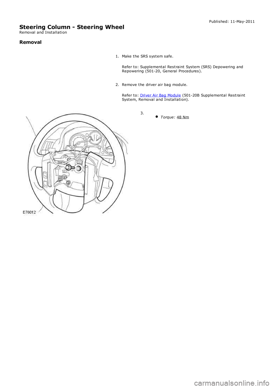
T orque: 48 Nm 3.
Page 590 of 3229
Publi s hed: 11-May-2011
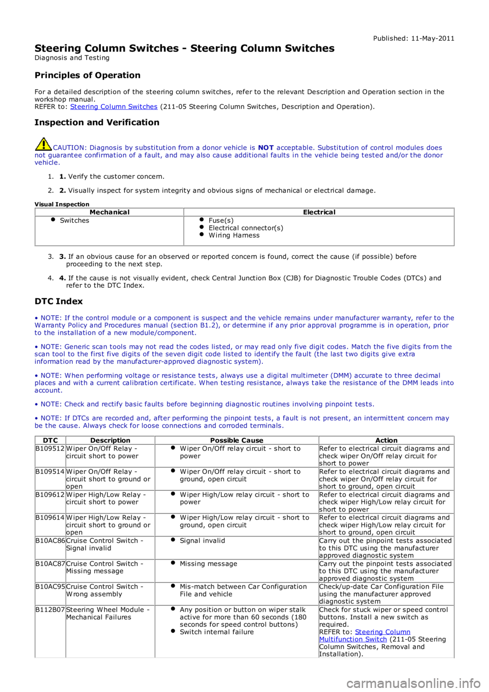
Steering Column Switches - Steering Column Switches
Diagnosi s and Tes ti ng
Principles of Operation
For a detail ed descripti on of the st eering col umn s wit ches , refer to t he relevant Des cript ion and O perati on sect ion i n theworks hop manual .REFER to: St eering Col umn Swit ches (211-05 St eering Col umn Swit ches , Des cript ion and Operat ion).
Inspection and Verification
CAUTION: Di agnos is by s ubs ti tut ion from a donor vehicle is NO T acceptabl e. Subs ti tut ion of cont rol modules doesnot guarant ee confirmat ion of a faul t, and may als o caus e addit ional fault s i n t he vehi cl e being t est ed and/or t he donorvehi cl e.
1. Verify t he cus t omer concern.1.
2. Vis ually ins pect for s ys tem int egrit y and obvi ous s igns of mechanical or el ect ri cal damage.2.
Visual InspectionMechanicalElectrical
Swit chesFus e(s)Electrical connect or(s)W i ri ng Harness
3. If an obvious cause for an obs erved or report ed concern is found, correct t he caus e (if pos s ible) beforeproceeding t o t he next s t ep.3.
4. If t he caus e is not vis ually evi dent , check Central Junct ion Box (CJB) for Diagnost ic Troubl e Codes (DTCs ) andrefer t o t he DTC Index.4.
DTC Index
• NOTE: If the control modul e or a component i s s us pect and the vehicle remains under manufacturer warrant y, refer t o theW arranty Pol icy and Procedures manual (s ect ion B1.2), or determine i f any pri or approval programme is in operat ion, pri ort o the ins tall ati on of a new module/component.
• NOTE: Generic scan t ool s may not read the codes li st ed, or may read only fi ve digit codes . Mat ch the five di git s from t hes can tool to the firs t fi ve di git s of the seven digi t code l is ted to ident ify t he faul t (t he las t t wo digi ts gi ve ext rainformat ion read by the manufact urer-approved diagnost ic s ys tem).
• NOTE: W hen performing volt age or res is t ance t est s , always use a digi tal mult imeter (DMM) accurat e t o t hree deci malplaces and wit h a current cal ibrat ion cert ificate. W hen tes ti ng res i st ance, always take the res is tance of the DMM l eads i ntoaccount.
• NOTE: Check and recti fy bas ic faul ts before beginni ng diagnos t ic rout ines i nvol vi ng pinpoint t es t s.
• NOTE: If DTCs are recorded and, aft er performi ng the pi npoi nt tes ts , a fault is not present , an int ermi tt ent concern maybe t he caus e. Always check for loose connect ions and corroded terminals .
DT CDescriptionPossible CauseActionB109512W iper On/Off Relay -circui t s hort t o powerW iper On/Off rel ay ci rcuit - s hort t opowerRefer t o el ect ri cal circui t di agrams andcheck wiper On/Off rel ay ci rcuit fors hort t o power
B109514W iper On/Off Relay -circui t s hort t o ground oropen
W iper On/Off rel ay ci rcuit - s hort t oground, open circuitRefer t o el ect ri cal circui t di agrams andcheck wiper On/Off rel ay ci rcuit fors hort t o ground, open ci rcuit
B109612W iper High/Low Rel ay -circui t s hort t o powerW iper High/Low relay ci rcuit - s hort t opowerRefer t o el ect ri cal circui t di agrams andcheck wiper High/Low relay ci rcuit fors hort t o powerB109614W iper High/Low Rel ay -circui t s hort t o ground oropen
W iper High/Low relay ci rcuit - s hort t oground, open circuitRefer t o el ect ri cal circui t di agrams andcheck wiper High/Low relay ci rcuit fors hort t o ground, open ci rcuit
B10AC86Cruis e Control Swi tch -Si gnal invali dSi gnal invali dCarry out t he pinpoint t es t s as sociat edt o t his DTC us i ng the manufact urerapproved diagnost ic sys tem
B10AC87Cruis e Control Swi tch -Mi s si ng mes s ageMi s si ng mes s ageCarry out t he pinpoint t es t s as sociat edt o t his DTC us i ng the manufact urerapproved diagnost ic sys temB10AC95Cruis e Control Swi tch -W rong as s emblyMi s -mat ch between Car Configurat ionFi le and vehicleCheck/up-date Car Configurat ion Fil eus ing the manufact urer approveddi agnos ti c s ys t em
B112B07St eering W heel Module -Mechani cal Fail uresAny pos it ion or butt on on wi per st alkacti ve for more t han 60 s econds (180s econds for speed control but tons )Swi tch i nternal fai lure
Check for s t uck wi per or s peed cont rolbut tons . Ins tal l a new s wit ch asrequi red.REFER t o: St eeri ng ColumnMul ti functi on Swit ch (211-05 St eeringCol umn Swit ches , Removal andIns tall ati on).
Page 1078 of 3229
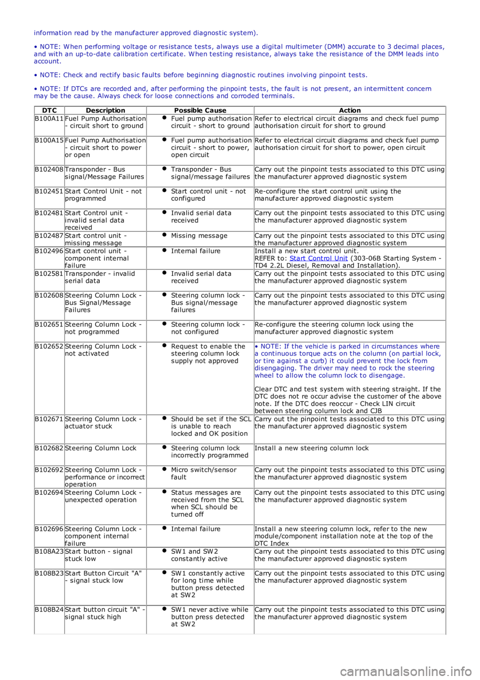
informat ion read by the manufact urer approved diagnos t ic s ys tem).
• NOTE: W hen performing volt age or res is t ance t est s , always use a digi tal mult imeter (DMM) accurat e t o 3 decimal places,and wit h an up-to-dat e cali brati on cert ificat e. W hen t est ing res is tance, al ways take t he res i st ance of t he DMM leads int oaccount.
• NOTE: Check and recti fy bas ic faul ts before beginni ng diagnos t ic rout ines i nvol vi ng pinpoint t es t s.
• NOTE: If DTCs are recorded and, aft er performi ng the pi npoi nt tes ts , t he fault i s not pres ent , an i nt ermit tent concernmay be t he cause. Always check for loos e connecti ons and corroded t ermi nal s.
DT CDescriptionPossible CauseAction
B100A11Fuel Pump Authori s at ion- ci rcuit s hort t o groundFuel pump aut horis at ioncircui t - short to groundRefer to el ect ri cal circui t diagrams and check fuel pumpaut horis at ion circui t for s hort t o ground
B100A15Fuel Pump Authori s at ion- ci rcuit s hort t o poweror open
Fuel pump aut horis at ioncircui t - short to power,open circuit
Refer to el ect ri cal circui t diagrams and check fuel pumpaut horis at ion circui t for s hort t o power, open circuit
B102408Trans ponder - Buss i gnal/Mes sage Fail uresTrans ponder - Buss ignal/mes sage failuresCarry out t he pinpoint t est s as s ociat ed t o t hi s DTC us ingthe manufact urer approved di agnos t ic s yst em
B102451St art Control Uni t - notprogrammedStart cont rol unit - notconfiguredRe-configure the s t art control unit us i ng themanufact urer approved diagnos t ic s ys tem
B102481St art Control uni t -i nval id s eri al dat arecei ved
Invali d s eri al dat areceivedCarry out t he pinpoint t est s as s ociat ed t o t hi s DTC us ingthe manufact urer approved di agnos t ic s yst em
B102487St art control unit -mis s ing mes s ageMi ss ing mess ageCarry out t he pinpoint t est s as s ociat ed t o t hi s DTC us ingthe manufact urer approved di agnos t ic s yst emB102496St art control unit -component i nternalfail ure
Int ernal fai lureIns tal l a new s tart cont rol unit .REFER t o: Start Cont rol Unit (303-06B St art ing Syst em -TD4 2.2L Di es el, Removal and Ins t al lat ion).
B102581Trans ponder - i nval ids eri al dat aInvali d s eri al dat areceivedCarry out t he pinpoint t est s as s ociat ed t o t hi s DTC us ingthe manufact urer approved di agnos t ic s yst em
B102608St eering Col umn Lock -Bus Si gnal /Mes s ageFail ures
Steering column lock -Bus s ignal/mes sagefai lures
Carry out t he pinpoint t est s as s ociat ed t o t hi s DTC us ingthe manufact urer approved di agnos t ic s yst em
B102651St eering Col umn Lock -not programmedSteering column lock -not configuredRe-configure the s t eering column lock us ing t hemanufact urer approved diagnos t ic s ys tem
B102652St eering Col umn Lock -not acti vat edReques t t o enabl e t hes teering column l ocks uppl y not approved
• NOTE: If t he vehi cle i s parked in ci rcums tances wherea cont inuous torque act s on t he column (on part ial lock,or t ire agains t a curb) i t could prevent t he l ock fromdi s engaging. The dri ver may need t o rock the s t eeringwheel t o all ow t he col umn l ock t o di sengage.
Clear DTC and tes t s yst em wit h s teeri ng s traight. If t heDTC does not re occur advis e t he cus t omer of t he abovenot e. If t he DTC does reoccur - Check LIN ci rcuitbet ween s teeri ng column l ock and CJB
B102671St eering Col umn Lock -actuat or st uckShoul d be s et if t he SCLis unable to reachlocked and OK pos it ion
Carry out t he pinpoint t est s as s ociat ed t o t hi s DTC us ingthe manufact urer approved di agnos t ic s yst em
B102682St eering Col umn LockSteering column lockincorrect ly programmedIns tal l a new s teering column lock
B102692St eering Col umn Lock -performance or i ncorrectoperat ion
Mi cro s wit ch/s ens orfaul tCarry out t he pinpoint t est s as s ociat ed t o t hi s DTC us ingthe manufact urer approved di agnos t ic s yst em
B102694St eering Col umn Lock -unexpect ed operati onStat us mes s ages arereceived from the SCLwhen SCL s houl d bet urned off
Carry out t he pinpoint t est s as s ociat ed t o t hi s DTC us ingthe manufact urer approved di agnos t ic s yst em
B102696St eering Col umn Lock -component i nternalfail ure
Int ernal fai lureIns tal l a new s teering column lock, refer to the newmodul e/component i ns t allat ion not e at t he top of t heDTC IndexB108A23St art butt on - s ignals t uck l owSW 1 and SW 2cons t ant ly act iveCarry out t he pinpoint t est s as s ociat ed t o t hi s DTC us ingthe manufact urer approved di agnos t ic s yst em
B108B23St art But ton Ci rcuit "A"- s i gnal s tuck l owSW 1 cons tant ly acti vefor l ong ti me whi lebutt on pres s detect edat SW 2
Carry out t he pinpoint t est s as s ociat ed t o t hi s DTC us ingthe manufact urer approved di agnos t ic s yst em
B108B24St art butt on circui t "A" -s i gnal s tuck highSW 1 never act ive whi lebutt on pres s detect edat SW 2
Carry out t he pinpoint t est s as s ociat ed t o t hi s DTC us ingthe manufact urer approved di agnos t ic s yst em
Page 1293 of 3229
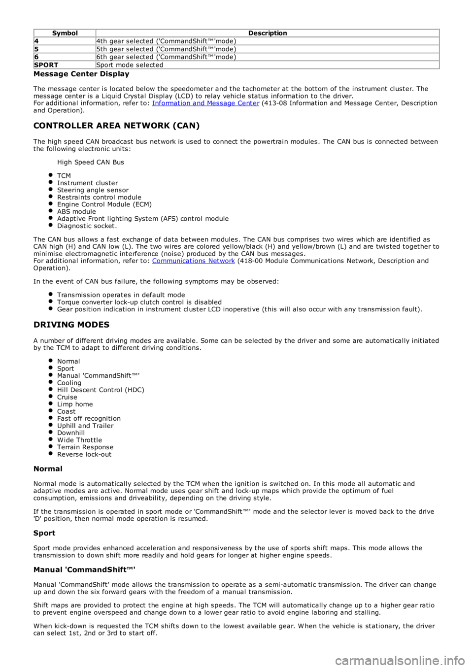
SymbolDescription
44th gear s elected ('CommandShift™ 'mode)
55th gear s elected ('CommandShift™ 'mode)66th gear s elected ('CommandShift™ 'mode)
SPORTSport mode s elected
Message Center Display
The mes s age center i s located bel ow t he speedometer and t he tachometer at t he bot t om of t he ins trument cl ust er. Themes s age center i s a Liqui d Crys tal Di spl ay (LCD) t o rel ay vehi cl e s tat us informat ion t o t he dri ver.For addit ional informat ion, refer t o: Informat ion and Mes s age Cent er (413-08 Informat ion and Mes s age Cent er, Des cript ionand Operat ion).
CONTROLLER AREA NETWORK (CAN)
The high s peed CAN broadcast bus net work i s us ed to connect t he powert rai n modules . The CAN bus is connect ed betweent he foll owing el ect ronic uni ts :
High Speed CAN Bus
TCMIns t rument clus terSteering angle s ens orRest rai nts control modul eEngi ne Control Module (ECM)ABS moduleAdapt ive Front l ight ing Syst em (AFS) cont rol moduleDiagnost ic socket .
The CAN bus all ows a fast exchange of dat a between modules . The CAN bus compri ses two wires which are identi fied asCAN hi gh (H) and CAN low (L). The t wo wires are colored yel low/bl ack (H) and yell ow/brown (L) and are twi s ted t oget her tomi ni mi se el ect romagneti c int erference (nois e) produced by the CAN bus mes sages .For addit ional informat ion, refer t o: Communicati ons Net work (418-00 Modul e Communicati ons Net work, Des cript ion andOperat ion).
In the event of CAN bus fai lure, t he fol lowi ng s ympt oms may be obs erved:
Trans mis s ion operat es in default modeTorque converter lock-up clut ch cont rol is dis abl edGear pos it ion indicati on in ins trument cl us t er LCD inoperati ve (t his will al so occur wit h any t rans mis s ion faul t).
DRIVING MODES
A number of different dri ving modes are avai lable. Some can be s elected by the driver and some are aut omati cal ly i nit iatedby t he TCM t o adapt t o di fferent drivi ng condit ions .
NormalSportManual 'CommandShift ™'CoolingHil l Descent Cont rol (HDC)Crui seLimp homeCoastFast off recogni ti onUphill and TrailerDownhillW i de Throt tl eTerrai n Res pons eRevers e lock-out
Normal
Normal mode is automat icall y s elect ed by t he TCM when t he i gni ti on is swi tched on. In this mode all automat ic andadapt ive modes are acti ve. Normal mode uses gear s hi ft and l ock-up maps which provi de the opt imum of fuelcons umpt ion, emis s ions and dri veabil it y, depending on t he dri ving s tyl e.
If the t rans mis s ion is operat ed in sport mode or 'CommandShi ft ™' mode and t he s elector lever is moved back t o t he drive'D' pos it ion, then normal mode operat ion is resumed.
Sport
Sport mode provi des enhanced accelerat ion and respons ivenes s by t he us e of s ports shi ft maps . This mode al lows t het ransmis s ion t o down s hift more readil y and hol d gears for longer at hi gher engine speeds .
Manual 'CommandShift™'
Manual 'CommandShift ' mode al lows t he t rans mis s ion t o operat e as a semi -aut omati c trans mi s si on. The driver can changeup and down t he s ix forward gears wi th the freedom of a manual t rans mis s ion.
Shift maps are provi ded to protect t he engi ne at high s peeds . The TCM wi ll automat icall y change up t o a higher gear rat iot o prevent engine overspeed and change down to a lower gear rati o t o avoi d engine l aboring and s t al li ng.
W hen ki ck-down is reques ted the TCM shi ft s down t o t he lowes t avai lable gear. W hen the vehicl e is st ati onary, t he drivercan s el ect 1s t , 2nd or 3rd t o s tart off.
Page 1920 of 3229
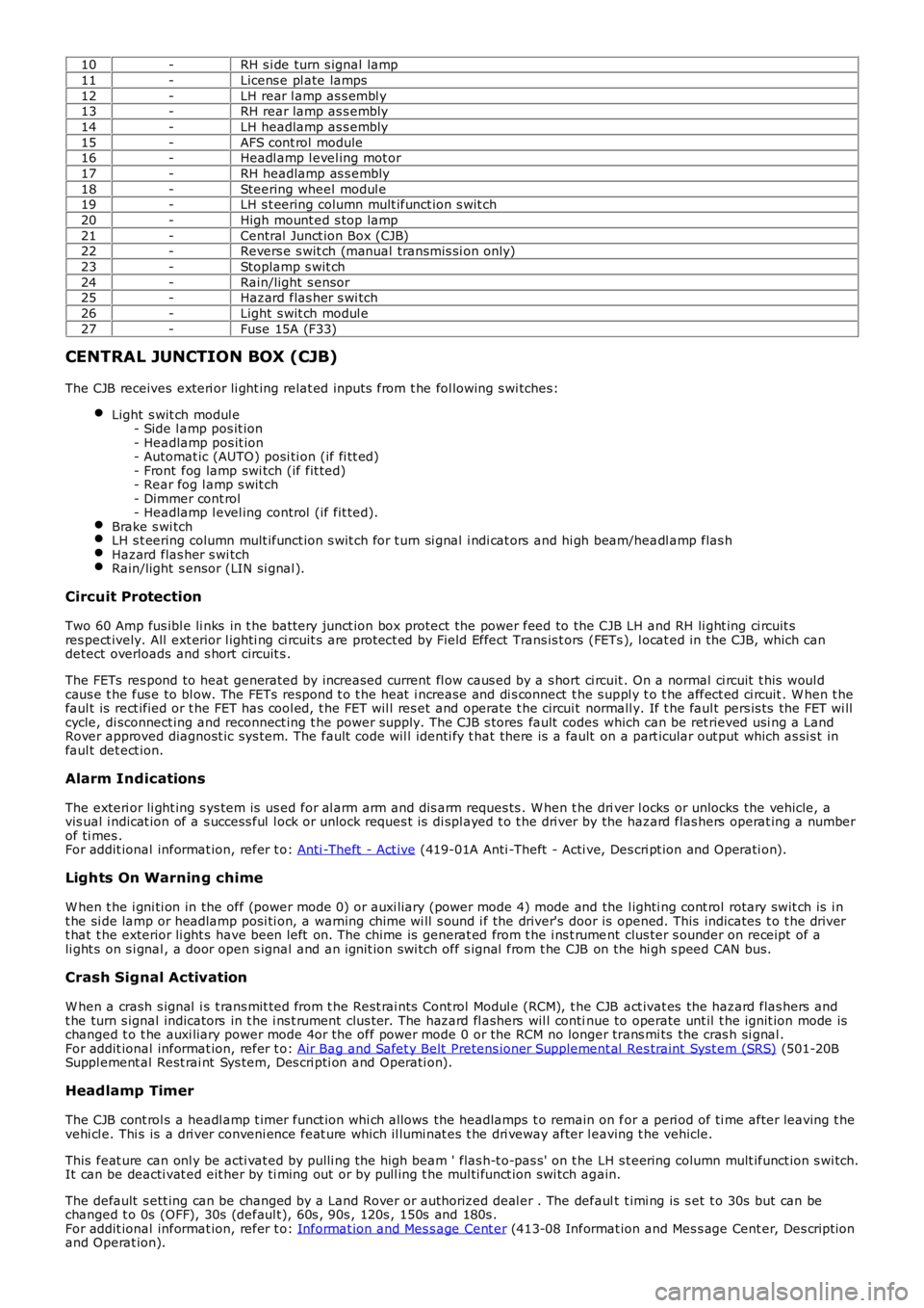
10-RH s i de turn s ignal lamp
11-Licens e pl ate lamps
12-LH rear l amp as s embl y13-RH rear lamp as s embly
14-LH headlamp as s embly
15-AFS cont rol module16-Headl amp l evel ing mot or
17-RH headlamp as s embly
18-Steering wheel modul e19-LH s t eering column mult ifunct ion s wit ch
20-High mount ed s top lamp
21-Central Junct ion Box (CJB)22-Revers e s wit ch (manual transmis si on only)
23-Stoplamp s wit ch
24-Rain/light s ensor25-Hazard flas her s wi tch
26-Light s wit ch modul e
27-Fuse 15A (F33)
CENTRAL JUNCTION BOX (CJB)
The CJB receives exteri or li ght ing relat ed inputs from t he fol lowing s wi tches:
Light s wit ch modul e- Side l amp pos it ion- Headlamp pos it ion- Automat ic (AUTO) posi ti on (if fi tt ed)- Front fog lamp swi tch (if fit ted)- Rear fog l amp s wit ch- Dimmer cont rol- Headlamp l evel ing control (if fit ted).Brake s wi tchLH s t eering column mult ifunct ion s wit ch for t urn si gnal i ndi cat ors and hi gh beam/headl amp flas hHazard flas her s wi tchRain/light s ensor (LIN si gnal ).
Circuit Protection
Two 60 Amp fus ibl e li nks in t he batt ery junct ion box protect the power feed to the CJB LH and RH li ght ing ci rcuit sres pect ively. All ext erior l ighti ng ci rcuit s are prot ect ed by Field Effect Trans is t ors (FETs ), l ocat ed in the CJB, which candetect overloads and s hort circuit s .
The FETs res pond to heat generated by increased current fl ow caus ed by a s hort ci rcuit . On a normal ci rcuit t his woul dcaus e t he fus e to bl ow. The FETs respond t o t he heat i ncrease and di s connect t he s uppl y t o t he affect ed ci rcuit . W hen t hefaul t is rect ified or t he FET has cool ed, t he FET wil l res et and operate t he circui t normall y. If t he faul t pers is ts the FET wi llcycle, di sconnect ing and reconnect ing t he power supply. The CJB s tores fault codes which can be ret rieved usi ng a LandRover approved diagnost ic sys tem. The fault code wil l identi fy t hat there is a fault on a part icular out put which as si s t infaul t det ect ion.
Alarm Indications
The exteri or li ght ing s ys tem is us ed for al arm arm and dis arm reques ts . W hen t he driver l ocks or unlocks the vehicle, avis ual i ndicat ion of a s uccess ful l ock or unlock reques t is di spl ayed t o t he dri ver by the hazard flas hers operat ing a numberof ti mes .For addit ional informat ion, refer t o: Anti -Theft - Act ive (419-01A Anti -Theft - Acti ve, Des cri pt ion and Operati on).
Lights On Warning chime
W hen t he i gni ti on in the off (power mode 0) or auxi liary (power mode 4) mode and the l ighti ng cont rol rotary swit ch is i nt he si de lamp or headlamp posi ti on, a warning chime wi ll s ound i f the driver's door is opened. This indicates t o t he dri vert hat t he exterior li ght s have been left on. The chime is generat ed from t he i ns t rument clus ter s ounder on receipt of ali ght s on s i gnal , a door open s ignal and an ignit ion swi tch off s ignal from t he CJB on the hi gh s peed CAN bus.
Crash Signal Activation
W hen a crash s ignal i s t rans mit ted from t he Rest rai nts Cont rol Modul e (RCM), t he CJB act ivat es the hazard flas hers andt he turn s ignal indicators in t he i ns t rument clus ter. The hazard fl ashers wil l continue to operate unt il t he ignit ion mode ischanged t o t he auxi liary power mode 4or the off power mode 0 or the RCM no longer trans mi ts the cras h si gnal .For addit ional informat ion, refer t o: Air Bag and Safet y Belt Pretens ioner Supplement al Res traint Syst em (SRS) (501-20BSuppl ement al Rest rai nt Sys tem, Des cri pti on and Operati on).
Headlamp Timer
The CJB cont rol s a headl amp t imer funct ion whi ch allows the headlamps t o remain on for a peri od of ti me after leaving t hevehi cl e. Thi s is a dri ver conveni ence feat ure which il lumi nat es t he dri veway after leaving t he vehicle.
This feat ure can onl y be acti vat ed by pulli ng t he high beam ' flas h-t o-pas s' on t he LH s t eering column mult ifunct ion s wi tch.It can be deacti vat ed eit her by ti ming out or by pull ing t he mul ti funct ion swi tch again.
The default s ett ing can be changed by a Land Rover or authorized deal er . The default t imi ng is s et t o 30s but can bechanged t o 0s (OFF), 30s (defaul t), 60s , 90s , 120s , 150s and 180s .For addit ional informat ion, refer t o: Informat ion and Mes s age Cent er (413-08 Informat ion and Mes s age Cent er, Des cript ionand Operat ion).