2006 LAND ROVER FRELANDER 2 power steering
[x] Cancel search: power steeringPage 1922 of 3229
The automat ic headlamp s ys tem uses a li ght s ens or and t he CJB, which are connect ed via the LIN bus t o cont rol t heheadl amp funct ional it y.
A l ight s ens or is incorporated in t he rai n/l ight s ens or located on the i nsi de of the windshi el d, bel ow t he rear view mirror.The wiper s yst em al s o uses the rain/l ight s ens or for aut omati c wiper operati on.For addit ional informat ion, refer t o: W i pers and W as hers (501-16 W ipers and W as hers , Des cri pti on and Operati on).
The li ght sens or meas ures the ambi ent l ight around t he vehi cl e i n a vert ical direct ion and als o the angular li ght l evel fromt he front of t he vehi cle. The rai n/li ght sens or us es vehicle s peed s ignals , wiper s wit ch posi ti on and the park posi ti on of thefront wipers to control the s ys tem.
The automat ic headlamp operat ion us es ambient l ight levels whi ch are moni tored by phot odiodes incorporat ed in t herai n/l ight sens or. The rain/l ight s ens or s ends a li ght s on/off request t o t he CJB on t he LIN bus , which res ponds bys wit chi ng on t he low beam headl amps, front s ide l amps, l icense plate lamps and rear t ail l amps. The aut omat ic headlampsare act ivated under the foll owing condi ti ons :
Twil ightDarknessRainTunnel sUnderground or mult is t ori ed car parks .
Operat ion of t he aut omat ic headl amps requires t he ignit ion t o be on (power mode 6), the l ighti ng cont rol rot ary swi tch t obe i n the 'AUTO' pos it ion and a li ght s on reques t s ignal from t he li ght sens or.
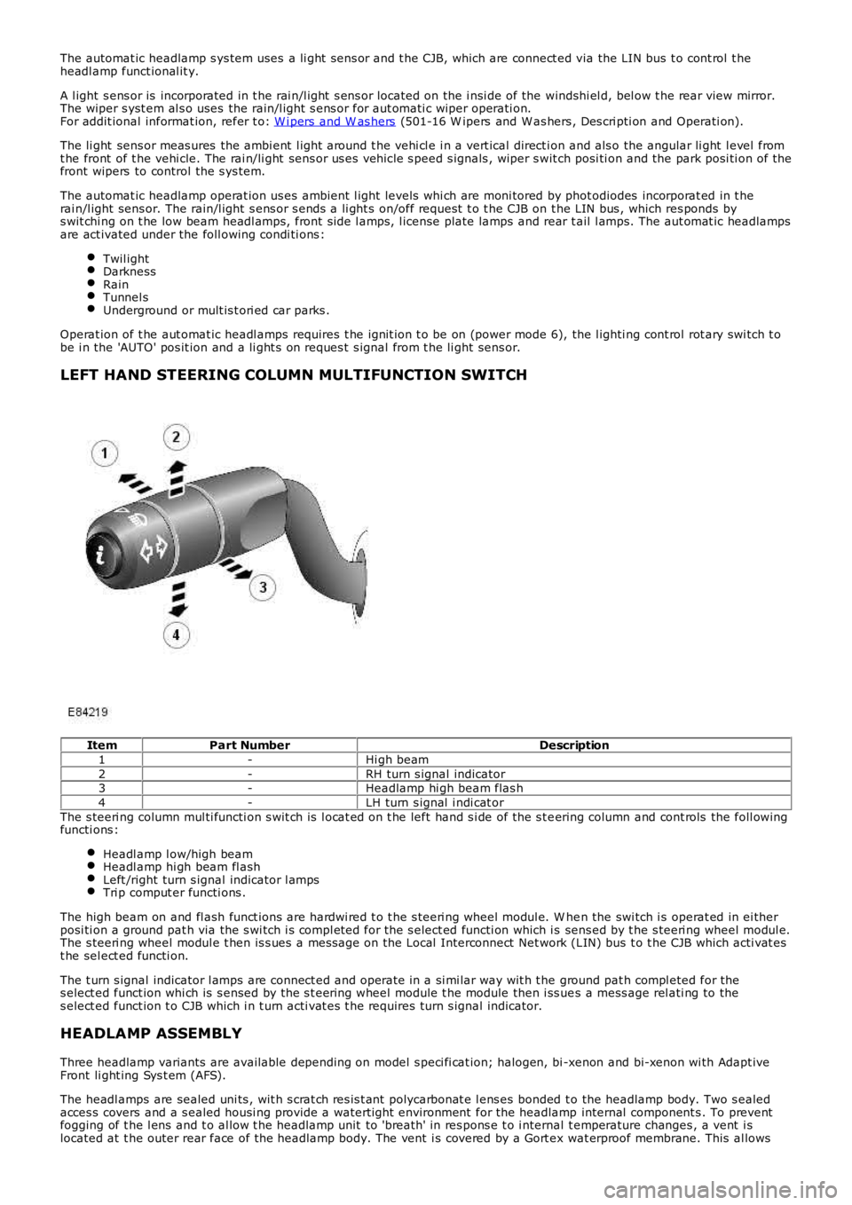
LEFT HAND STEERING COLUMN MULTIFUNCTION SWITCH
ItemPart NumberDescription
1-Hi gh beam
2-RH turn s ignal indicator3-Headlamp hi gh beam flas h
4-LH turn s ignal i ndi cat or
The s teeri ng column mul ti functi on s wit ch is l ocat ed on t he left hand s i de of the s t eering column and cont rols the foll owingfuncti ons :
Headl amp l ow/high beamHeadl amp hi gh beam fl ashLeft /right turn s ignal indicator l ampsTri p comput er functi ons .
The high beam on and fl ash funct ions are hardwi red t o t he s teeri ng wheel modul e. W hen the swi tch i s operat ed in ei therposi ti on a ground pat h via the s wi tch i s compl eted for the s elect ed functi on which is sens ed by t he s teeri ng wheel modul e.The s teeri ng wheel modul e t hen is s ues a mes sage on the Local Interconnect Net work (LIN) bus t o t he CJB which acti vat est he sel ect ed functi on.
The t urn s ignal indicator l amps are connect ed and operate in a si mi lar way wit h t he ground pat h compl eted for thes elect ed funct ion whi ch is s ensed by the s t eering wheel module t he module then i ss ues a mess age rel ati ng to thes elect ed funct ion t o CJB which i n t urn acti vat es t he requires turn s ignal indicator.
HEADLAMP ASSEMBLY
Three headlamp variants are available depending on model s peci fi cat ion; halogen, bi -xenon and bi-xenon wi th Adapt iveFront li ght ing Sys t em (AFS).
The headl amps are sealed uni ts , wit h s crat ch res is t ant polycarbonat e l ens es bonded to the headlamp body. Two s ealedacces s covers and a s ealed housi ng provide a waterti ght environment for the headlamp internal component s . To preventfogging of t he l ens and t o al low t he headlamp unit to 'breath' in res pons e t o i nternal t emperature changes , a vent i slocated at t he outer rear face of the headlamp body. The vent i s covered by a Gort ex wat erproof membrane. This al lows
Page 2697 of 3229
Publ is hed: 11-May-2011
Uni-Body, Subframe and Mounting System - Front SubframeRemoval and Installation
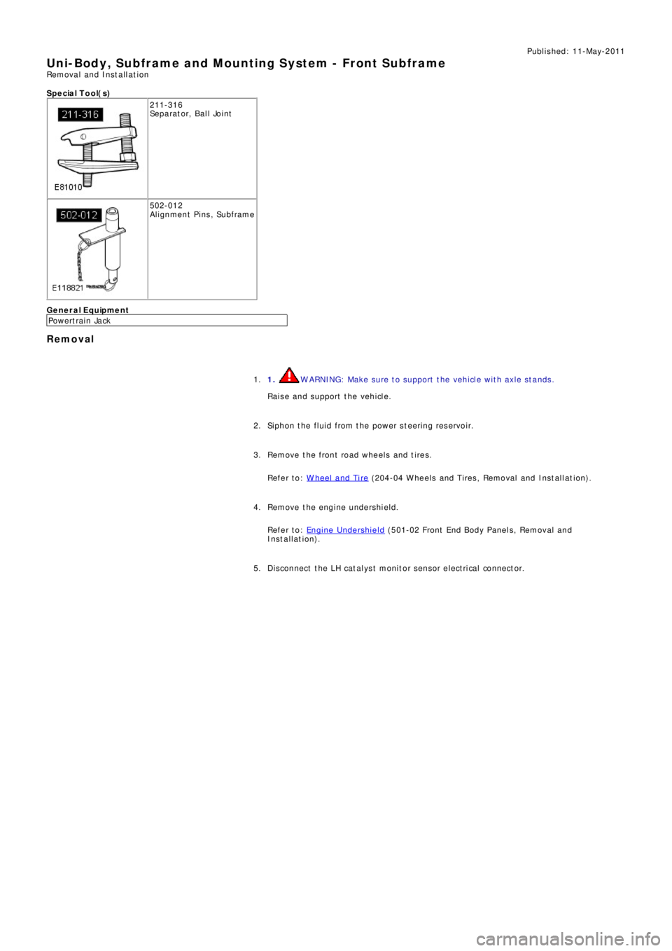
S p e c ia l T o o l( s )
211-316
Se p a ra t o r, B a l l Jo i nt
502-012
Alignment Pins, Subframe
General Equipment
P o we rt ra i n Ja ck
Removal
1. WARNING: Make sure to support the vehicle with axle stands.
Raise and support the vehicle. 1.
Siphon the fluid from the power steering reservoir. 2.
Remove the front road wheels and tires.
Refer to: W heel and Tire
(204-04 W heels and Tires , Removal and Ins t all at i on). 3.
Remove the engine undershield.
Refer to: Engine Undershield
(501-02 Front End Body Panel s, Removal and
Installation). 4.
Di sconnect t he LH cat al ys t monit or sens or elect ri cal connect or. 5.
Page 2699 of 3229
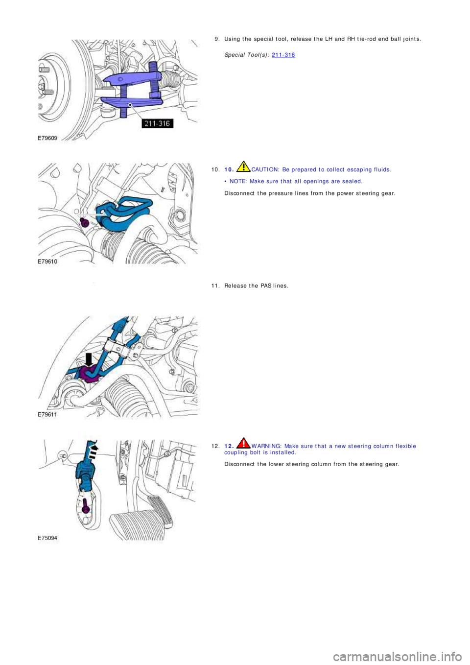
Using the special tool, release the LH and RH tie-rod end ball joints.
Special Tool(s): 211-3169.
10. CAUTION: Be prepared to collect escaping fluids.
• NOTE: Make sure that all openings are sealed.
Disconnect the pressure lines from the power steering gear. 10.
Release the PAS lines. 11.
12. WARNING: Make sure that a new steering column flexible
coupling bolt is installed.
Disconnect the lower steering column from the steering gear. 12.
Page 2704 of 3229
18. WARNING: Make sure that a new steering column flexible coupling bolt is
installed.
Connect the steering column to the steering gear.
Torque: 25 Nm18.
Connect and s ecure t he cat alys t moni t or s ens or el ect ri cal connect ors . 19.
Install the 2 subframe mounting bolts and remove the jack. 20.
Install the engine undershield.
Refer to: Engine Undershield
(501-02 Front End Body Panel s, Removal and
Installation). 21.
Install the wheels and tires.
Refer to: W heel and Tire
(204-04 W heels and Tires , Removal and Ins t all at i on). 22.
Refill and bleed the power steering.
Refer to: Power Steering System Bleeding
(211-00 St eeri ng Sys t em - General
Informat ion, General Procedures). 23.
Using only four wheel alignment equipment approved by Land Rover, check and adjust
the wheel alignment. 24.
Page 2725 of 3229

Contents
5
R
ENGINE COOLANT CHECK ............................ 163
BRAKE AND CLUTCH FLUID CHECK ............. 165
POWER STEERING FLUID CHECK ................ 166
WASHER FLUID CHECK ................................ 167
TECHNICAL SPECIFICATIONS ...................... 169
Vehicle battery
BATTERY WARNING SYMBOLS ................... 171
BATTERY CARE ............................................ 171
USING BOOSTER CABLES ............................ 173
CHARGING THE VE HICLE BATTERY ............. 174
CHANGING THE VE HICLE BATTERY ............. 174
Wheels and tyres
GENERAL INFORMATION ............................. 176
TYRE CARE ................................................... 177
USING WINTER TYRES................................. 183
CHANGING A ROAD WHEEL ......................... 183
TYRE REPAIR KIT ......................................... 187
USING SNOW CHAINS.................................. 192
TYRE GLOSSARY.......................................... 193
TECHNICAL SPECIFICATIONS ...................... 194
Fuses
FUSE BOX LOCATIONS ................................. 195
CHANGING A FUSE ....................................... 195
FUSE SPECIFICATION CHART....................... 196
Emergency equipment
HAZARD WARNING FLASHERS .................... 204
WARNING TRIANGLE ................................... 204
Status after a collision
DRIVING AFTER A COLLISION...................... 205
INSPECTING SAFETY SYSTEM COMPONENTS ...
206
Vehicle recovery
TOWING POINTS .......................................... 207
LASHING POINTS ......................................... 208
TRANSPORTING THE VEHICLE..................... 208
TOWING THE VEHICLE ON FOUR WHEELS .. 208
Vehicle identification
VEHICLE IDENTIFICATION PLATE................. 210
VEHICLE IDENTIFI CATION NUMBER (VIN) ... 210
VEHICLE BUILD DATE PLATE ....................... 210
Technical specifications
ENGINE SPECIFICATIONS ............................ 211
WEIGHTS...................................................... 212
DIMENSIONS................................................ 213
Type approval
Declarations of conformity ........................... 215
Audio introduction
RADIO RECEPTION....................................... 218
Audio unit overview
AUDIO UNIT OVERVIEW............................... 219
Audio unit operation
ON OR OFF CONTROL .................................. 223
VOLUME CONTROL ...................................... 223
AUDIO CONTROL ......................................... 223
WAVEBAND BUTTON ................................... 224
AUTOSTORE CONTROL ................................ 225
STATION PRESET BUTTONS ........................ 226
TRAFFIC INFORMATION CONTROL .............. 226
Audio unit menus
RADIO DATA SYSTEM (RDS) ....................... 228
REGIONAL MODE (REG) .............................. 228
ENHANCED OTHER NETWORK (RDS-EON).. 229
ALTERNATIVE FREQUENCIES ...................... 229
NEWS BROADCASTS ................................... 230
PRIORITY PROGRAMME TYPE (PTY) .......... 231
RESETTING THE AUDIO UNIT ...................... 233
Digital audio broadcasting
GENERAL INFORMATION ............................. 234
AUDIO CONTROLS ....................................... 235
DISPLAY OPTIONS ....................................... 236
CHANNEL AUTOMATIC TUNING................... 236
CHANNEL OPTIONS ..................................... 236
PRESET BUTTONS ....................................... 238
SETTINGS..................................................... 240
Compact disc player
LOADING COMPACT DISCS ......................... 245
EJECTING COMPACT DISCS ........................ 246
EJECTING MULTIPLE CO MPACT DISCS....... 246
COMPACT DISC SELECTION ........................ 246
COMPACT DISC PLAYBACK ......................... 246
Page 2860 of 3229
Stability control
140
L
Stability controlPRINCIPLE OF OPERATION
Dynamic Stability Control (DSC)
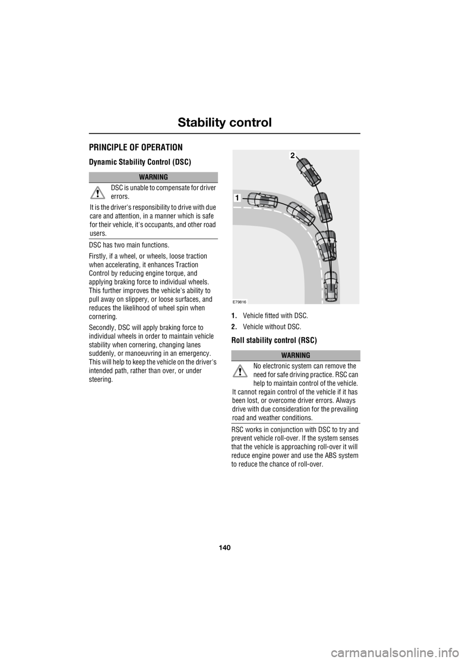
DSC has two main functions.
Firstly, if a wheel, or wheels, loose traction
when accelerating, it enhances Traction
Control by reducing engine torque, and
applying braking force to individual wheels.
This further improves the vehicle's ability to
pull away on slippery, or loose surfaces, and
reduces the likelihood of wheel spin when
cornering.
Secondly, DSC will apply braking force to
individual wheels in orde r to maintain vehicle
stability when cornering, changing lanes
suddenly, or manoeuvring in an emergency.
This will help to keep the vehicle on the driver's
intended path, rather than over, or under
steering. 1.
Vehicle fitted with DSC.
2. Vehicle without DSC.
Roll stability control (RSC)
RSC works in conjunction with DSC to try and
prevent vehicle roll-over. If the system senses
that the vehicle is approaching roll-over it will
reduce engine power and use the ABS system
to reduce the chance of roll-over.
WARNING
DSC is unable to compensate for driver
errors.
It is the driver's responsibility to drive with due
care and attention, in a manner which is safe
for their vehicle, it's oc cupants, and other road
users.
WARNING
No electronic system can remove the
need for safe drivin g practice. RSC can
help to maintain control of the vehicle.
It cannot regain control of the vehicle if it has
been lost, or overcome driver errors. Always
drive with due consideration for the prevailing
road and weather conditions.
1
2
E79816
Page 2878 of 3229
Maintenance
158
L
One or both types of serv ice interval (distance
and time) may be displayed. For example, if an
engine oil service is du e based on mileage, and
a brake fluid change is due based on time, both
distance and time c ountdowns will display.
Service Portfolio
The Service Portfolio book includes a Service
Record section, which enables a record to be
kept of all the servicing and inspections that are
carried out on the vehicle. This section of the
book also has an area for brake fluid changes
to be recorded.
Ensure your service provider signs and stamps
the book after each se rvice and inspection.
Owner Maintenance
In addition to the routine maintenance, a
number of simple checks must be carried out
more frequently. Advice is given on the pages
that follow.
Daily checks
• Operation of lamps, horn, direction
indicators, wipers, washers and warning
indicators.
• Operation of seat belts and brakes.
• Look for fluid deposits underneath the
vehicle that might indicate a leak.
Weekly checks
• Engine oil level. See ENGINE OIL CHECK
(page 162).
• Engine coolant check. See ENGINE
COOLANT CHECK (page 163).
• Brake/clutch fluid level. See BRAKE AND
CLUTCH FLUID CHECK (page 165). •
Power steering fluid level. See POWER
STEERING FLUID CHECK (page 166).
• Screen washer fluid level. See WASHER
FLUID CHECK (page 167).
• Tyre pressure s and condition.
• Operate air conditioning.
Note: The engine oil leve l should be checked
more frequently if the vehicle is driven for
prolonged periods at high speeds.
Driving in arduous conditions
When a vehicle is operated in extremely
arduous conditions, more frequent attention
must be paid to servicing requirements.
For example, if your vehicle experiences deep
wading conditions, even daily servicing could
be necessary to ensure the continued safe and
reliable operation of the vehicle.
Arduous driving conditions include:
• Driving in dusty and/or sandy conditions.
• Driving on rough and/or muddy roads
and/or wading.
• Driving in extremely hot conditions.
• Towing a trailer or driving in mountainous
conditions.
Contact a Land Rover Dealer/Authorised
Repairer for advice.
Emission control
Your vehicle is fitted with various items of
emission and evaporative control equipment,
designed to meet sp ecific territorial
requirements. You should be aware that
unauthorised replacemen t, modification or
tampering with this equipment by an owner or
repair shop, may be unlawful and subject to
legal penalties.
CAUTION
Any significant or sudden drop in fluid
levels, or uneven tyre wear, should be
reported to a qualified technician without
delay.
Page 2879 of 3229
159
Maintenance
R
In addition, engine se ttings must not be
tampered with. These have been established to
ensure that your vehicle complies with
stringent exhaust em ission regulations.
Incorrect engine settings may adversely affect
exhaust emissions, engi ne performance and
fuel consumption. The y may also cause high
temperatures, which will result in damage to
the catalytic converter and the vehicle.
Road testing dynamometers (rolling
roads)
Because your vehicle is equipped with anti-lock
brakes and four wheel drive, it is essential that
any dynamometer testing is carried out only by
a qualified person, familiar with the
dynamometer testing an d safety procedures
practised by Land Rove r Dealers/Authorised
Repairers.
Safety in the garage
Fuel system
Poisonous fluids
Fluids used in motor vehicles are poisonous
and should not be consumed or brought into
contact with open wounds. These include;
battery acid, antifreeze, brake, clutch and
power steering fluid, petr ol, diesel, engine oil
and windscreen washer additives.
For your own safety, al ways read and obey all
instructions printed on labels and containers.
Used engine oil
Prolonged contact with engine oil may cause
serious skin disorders, including dermatitis
and cancer of the skin. Always wash
thoroughly after contact.
It is illegal to pollute drains, water
courses or soil. Use authorised
waste disposal sites to dispose of
used oil and toxic chemicals.
WARNINGS
If the vehicle has been driven recently,
do not touch exhaust and cooling
system components un til the engine has
cooled.
Never leave the engine running in an
unventilated area - exhaust gases are
poisonous and extremely dangerous.
Do not work beneath the vehicle with
the wheel changing jack as the only
means of support.
Keep your hands and clothing away
from drive belt s and pulleys.
Remove metal wr ist bands and
jewellery, before working in the engine
compartment.
Do not touch electrical leads or
components while the engine is
running, or with the starter switch turned on.
Do not allow tools or metal parts of the
vehicle to make contact with the battery
leads or terminals.
WARNINGS
Under no circumstances should any
part of the fuel system be dismantled or
replaced by anyone other than a suitably
qualified vehicle technician. Failure to comply
with this instruction, may result in fuel spillage
with a consequent serious risk of fire.
Ensure sparks and naked lights are kept
away from the engine compartment.
Wear protective cl othing, including,
where practicable, gloves made from
an impervious material.
WARNINGS