Page 540 of 3229

diamet er in i ts central sect ion. The smal ler diamet er allows the t ors ion bar t o t wist in res pons e t o t orque appli ed from t hes teeri ng wheel in relati on t o t he grip of the t yres on t he road surface. The pi nion s haft has machined t eet h on it s cent raldiamet er whi ch mat e wit h t eeth on the s t eering gear rack. A s lot , machi ned in t he upper end of t he pini on s haft mateswit h t he dog-t oot h on the i nput s haft . The pinion s haft l ocat es in the pi ni on housi ng and rot ates on bal l and roll erbearings .
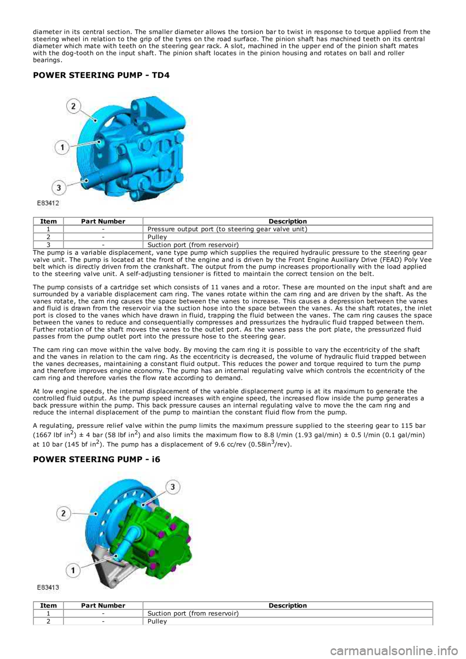
POWER STEERING PUMP - TD4
ItemPart NumberDescription1-Pres s ure out put port (t o s t eering gear val ve unit )
2-Pull ey
3-Sucti on port (from res ervoi r)The pump i s a vari abl e dis placement, vane t ype pump which s uppl ies t he required hydraulic pres sure t o the st eeri ng gearvalve unit . The pump is locat ed at t he front of t he engine and i s dri ven by the Front Engine Auxil iary Dri ve (FEAD) Poly Veebelt which i s direct ly driven from the cranks haft . The out put from t he pump i ncreas es proporti onall y wi th the l oad appl iedt o the st eeri ng val ve uni t. A s el f-adjus ti ng tens ioner is fit t ed to maint ai n t he correct t ens ion on the bel t.
The pump consi st s of a cart ridge s et which cons is t s of 11 vanes and a rot or. These are mount ed on t he input s haft and ares urrounded by a variable di spl acement cam ring. The vanes rotat e wit hin the cam ri ng and are driven by t he s haft. As thevanes rotat e, the cam ri ng caus es the space between t he vanes to increase. This causes a depres si on between t he vanesand fl uid i s drawn from t he res ervoir vi a t he suct ion hos e int o t he s pace between the vanes. As t he s haft rotat es , t he inl etport i s clos ed to the vanes which have drawn in fluid, t rapping t he fluid bet ween t he vanes . The cam ring caus es t he s pacebetween t he vanes to reduce and cons equenti ally compress es and pres s uri zes t he hydrauli c fl ui d t rapped between t hem.Furt her rotat ion of t he s haft moves the vanes t o the out let port . As t he vanes pas s t he port plat e, the pres s uri zed fl ui dpass es from the pump out let port into the press ure hose to the s t eering gear.
The cam ring can move wi thi n t he val ve body. By moving the cam ri ng it i s poss ibl e to vary t he eccentricit y of t he s haftand t he vanes i n rel ati on to the cam ri ng. As t he eccent rici ty i s decreased, t he volume of hydraulic flui d t rapped bet weent he vanes decreases , mai nt aining a cons t ant flui d output. This reduces t he power and torque required to turn t he pumpand t herefore improves engine economy. The pump has an int ernal regulati ng valve which controls t he eccentricit y of t hecam ring and t herefore vari es the flow rat e accordi ng to demand.
At low engi ne s peeds , the i nternal dis placement of the vari able di spl acement pump i s at it s maximum t o generate thecont rol led fluid out put. As t he pump s peed increas es wit h engine s peed, t he i ncreas ed flow ins ide t he pump generates aback press ure wit hin the pump. This back pres s ure causes an internal regul ati ng val ve to move t he the cam ri ng andreduce t he int ernal di spl acement of the pump to maint ian t he cons t ant flui d fl ow from the pump.
A regul ati ng, pres s ure reli ef val ve wit hin t he pump l imi ts the maxi mum press ure s uppl ied t o t he s teeri ng gear t o 115 bar
(1667 l bf in2) ± 4 bar (58 lbf i n2) and al so li mit s t he maximum fl ow t o 8.8 l/min (1.93 gal/min) ± 0.5 l /min (0.1 gal /min)
at 10 bar (145 bf i n2). The pump has a dis placement of 9.6 cc/rev (0.58i n3/rev).
POWER STEERING PUMP - i6
ItemPart NumberDescription
1-Sucti on port (from res ervoi r)
2-Pull ey
Page 544 of 3229
Publi s hed: 11-May-2011
Power Steering - Power Steering
Diagnosi s and Tes ti ng
For addit ional informat ion.REFER to: St eering Sys tem (211-00 Steeri ng Sys t em - General Informati on, Di agnos is and Tes ti ng).
Page 545 of 3229
Publi s hed: 11-May-2011
Power Steering - Power Steering Pressure TestTD4 2.2L Diesel
General Procedures
Special T ool(s)
211-011-01Valve Bl ock, Power Steeri ng Pres s ure Tes t
211-011-02Hos e, Power St eering Press ure Tes t
211-011-12Adapter, Power St eering Press ure Tes t
211-287Hos e and Gauge, Power St eering Pres s ure Tes t
Di sconnect t he bat t ery ground cable.
Refer t o: Specificati ons (414-00 Bat tery and Charging Sys tem -General Informat ion, Specificati ons).
1.
Remove t he engi ne cover.
Refer t o: Engi ne Cover - TD4 2.2L Dies el (501-05 Interior Tri m andOrnament ati on, Removal and Ins tal lat ion).
2.
3. W ARNING: Make sure t o s upport the vehicle wit h axles tands .
Rais e and s upport t he vehi cl e.
3.
Page 547 of 3229

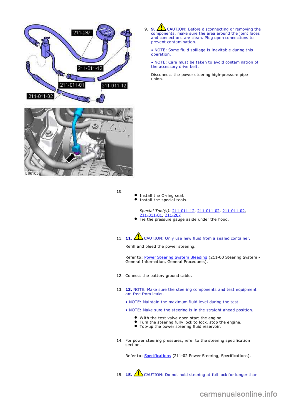
9. CAUTION: Before dis connecti ng or removing t he
component s, make sure t he area around t he joi nt faces
and connecti ons are clean. Plug open connecti ons to
prevent cont aminati on.
• NOTE: Some flui d s pill age is i nevi table during t his
operat ion.
• NOTE: Care mus t be taken t o avoid contami nat ion of
t he acces sory dri ve bel t.
Di sconnect t he power s t eering hi gh-pres s ure pi pe
union.
9.
Inst all t he O-ring seal. Inst all t he s pecial t ool s.
Speci al Tool (s ): 211-011-12 ,
211-011-02 ,
211-011-02 ,
211-011-01 ,
211-287 Tie the press ure gauge as ide under t he hood.10.
11. CAUTION: Only us e new fl uid from a s ealed container.
Refi ll and bleed t he power st eeri ng.
Refer t o: Power St eering Sys tem Bleeding (211-00 St eering Sys tem -
General Informat ion, General Procedures ).
11.
Connect t he batt ery ground cable.
12.
13. NOTE: Make sure t he s teeri ng components and tes t equi pment
are free from leaks .
• NOTE: Mai nt ain the maxi mum flui d level during t he t est .
• NOTE: Make s ure the s t eering i s i n the st rai ght ahead pos it ion. W it h the tes t val ve open s tart the engine. Turn the s t eering full y lock t o lock, st op t he engi ne.
Top-up t he power st eeri ng fl uid reservoi r.13.
For power s t eering press ures , refer to the s t eering s peci fi cat ion
s ect ion.
Refer t o: Specificati ons (211-02 Power Steering, Specificati ons ).
14.
15. CAUTION: Do not hold st eering at full l ock for longer t han
15.
Page 550 of 3229
Publi s hed: 11-May-2011
Power Steering - Power Steering Pressure TestI6 3.2L Petrol
General Procedures
Special T ool(s) 211-011-01
Valve Bl ock, Power Steeri ng Pres s ure Tes t 211-011-02
Hos e, Power St eering Press ure Tes t 211-011-11
Hos e, Power St eering Press ure Tes t 211-287
Hos e and Gauge, Power St eering Pres s ure Tes t 211-313
Adapter, Power St eering Press ure Tes t 211-325
Adapter, Power St eering Press ure Tes t
Di sconnect t he bat t ery ground cable.
Refer t o: Specificati ons (414-00 Bat tery and Charging Sys tem -
General Informat ion, Specificati ons).
1.
Remove t he air cleaner hous ing.
2.
Page 552 of 3229

Turn the s t eering full y lock-t o-l ock, s top t he engine.
Top-up t he power st eeri ng fl uid reservoi r.
For power s t eering press ures , refer to the s t eering s peci fi cat ion
s ect ion.
Refer t o: Specificati ons (211-02 Power Steering, Specificati ons ).
10.
11. CAUTION: Do not hold st eering at full l ock for longer t han
10 s econds .
W it h the engi ne at idle, s lowl y turn t he s teeri ng wheel and
hold on full l ock. Record t he pres s ure readi ng.11.
Repeat t he above procedure for t he other s ide. Record t he pres s ure readi ng.12.
W it h the engi ne at idle, rel ease the s t eering wheel. The press ure
s houl d be, at or bel ow, the pres s ure specified.
13.
Pres s ure out si de t hi s t olerance, i ndicat es a fault .
14.
15. CAUTION: Pump damage wi ll occur if t he t est valve is
clos ed for l onger peri ods .
To det ermi ne if t he fault is i n t he st eeri ng pump or the st eeri ng
rack, clos e the tes t val ve for a maxi mum of 5 s econds.
15.
If the press ures recorded fal l out s ide t he given values, replace the
power st eeri ng pump.
16.
If the maxi mum pump pres sure i s correct, t hen s uspect the power
s teering rack.
17.
18. CAUTION: Dis card flui d s iphoned from t he power st eeri ng
s yst em.
On compl et ion of t he t est s t op the engi ne, dis connect t he bat t ery
ground cable and s i phon t he fluid from t he power st eering res ervoir.
18.
Di sas s emble t he t es t equipment .
19.
Clean t he component mat ing faces . Inst all a new O-ring s eal.
Connect t he high-press ure pipe union t o t he power st eeri ng
pump. T orque:
25 Nm 20.
Inst all t he air cleaner hous ing.
Refer t o: Air Cleaner (303-12A Intake Ai r Dis tribut ion and Fil tering -
I6 3.2L Pet rol, Removal and Ins t al lat ion).
21.
Connect t he batt ery ground cable.
Refer t o: Specificati ons (414-00 Bat tery and Charging Sys tem -
General Informat ion, Specificati ons).
22.
Page 554 of 3229
Publi s hed: 11-May-2011
Power Steering - Power Steering PumpI6 3.2L Petrol
Removal and Inst all ati on
Removal
Remove t he cover and dis connect the bat tery ground cabl e.
Refer t o: Specificati ons (414-00 Bat tery and Charging Sys tem -General Informat ion, Specificati ons).
1.
Remove t he engi ne cover.
Refer t o: Engi ne Cover - I6 3.2L Pet rol (501-05 Int eri or Trim andOrnament ati on, Removal and Ins tal lat ion).
2.
Remove t he bat t ery t ray.
Refer t o: Bat t ery Tray (414-01 Bat tery, Mount ing and Cables ,Removal and Ins tall ati on).
3.
Remove t he air cleaner as s embly.
Refer t o: Air Cleaner (303-12A Intake Ai r Dis tribut ion and Fil tering -I6 3.2L Pet rol, Removal and Ins t al lat ion).
4.
Siphon t he fl uid from t he power s t eering res ervoi r.5.
Remove t he A/C compress or, l ower support bracket.6.
Us ing s uit able t ools , rel eas e t he acces s ory drive beltt ens i on.7.
Page 557 of 3229

Publi s hed: 11-May-2011
Power Steering - Power Steering PumpTD4 2.2L Diesel
Removal and Inst all ati on
Removal
CAUTION: Always pl ug any open connect ions t o prevent cont aminati on.
Remove t he engi ne cover.
Refer t o: Engi ne Cover - TD4 2.2L Dies el (501-05 Interior Tri m andOrnament ati on, Removal and Ins tal lat ion).
1.
Remove t he acces sory dri ve bel t.
Refer t o: Acces sory Dri ve Belt (303-05B Acces sory Drive - TD4 2.2LDi es el, Removal and Ins tal lat ion).
2.
3. W ARNING: Power s t eering fluid is ext remely fl ammable.Make s ure that power s t eering flui d is not s pil t over t he engine andt hat t he power s teeri ng fl uid reservoi r cap is s ealed.
Siphon t he fl uid from t he power s t eering res ervoi r.
3.
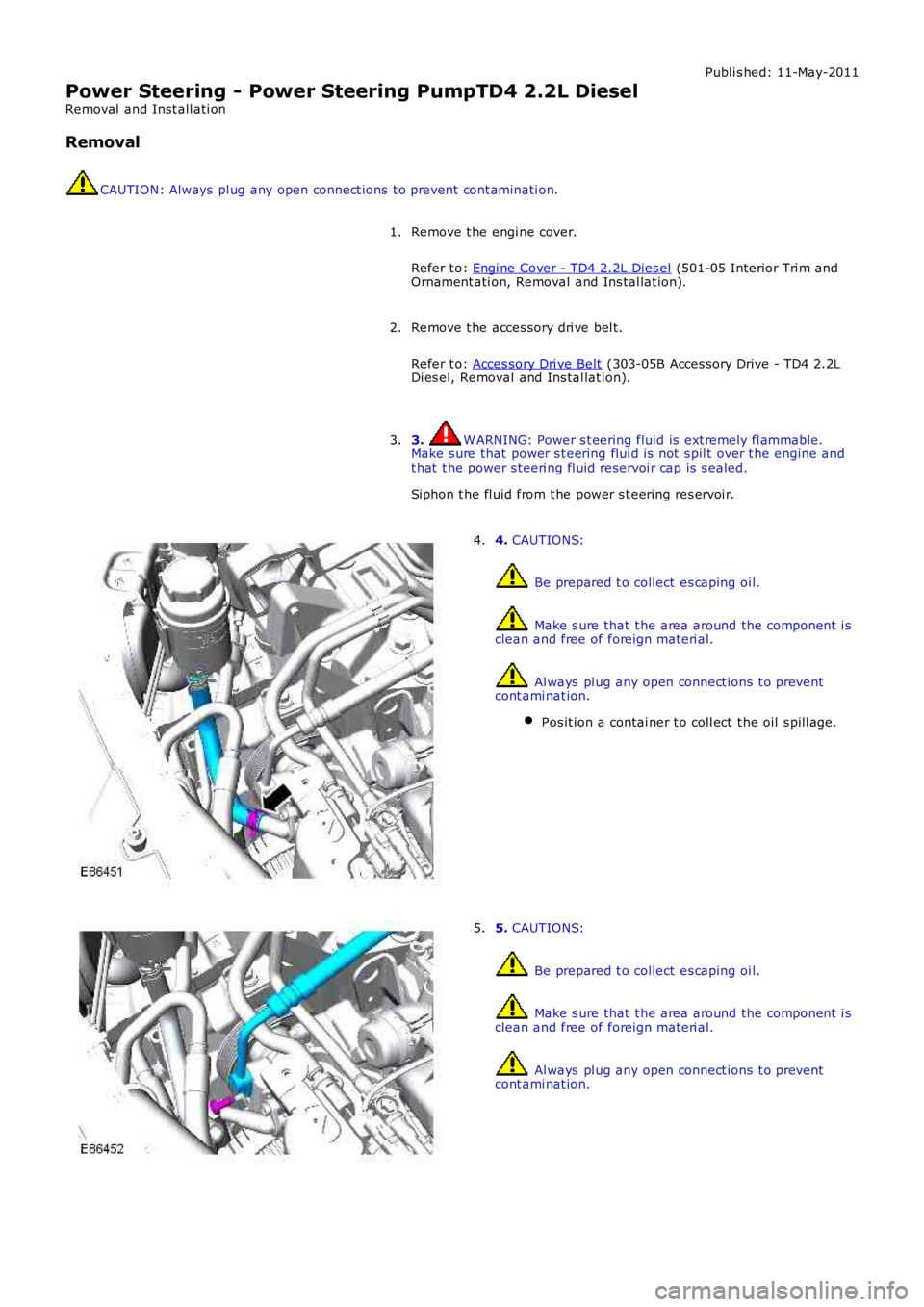
4. CAUTIONS:
Be prepared t o collect es caping oi l.
Make s ure that t he area around the component i sclean and free of foreign materi al.
Al ways pl ug any open connect ions t o preventcont ami nat ion.
Pos it ion a contai ner t o coll ect t he oil s pill age.
4.
5. CAUTIONS:
Be prepared t o collect es caping oi l.
Make s ure that t he area around the component i sclean and free of foreign materi al.
Al ways pl ug any open connect ions t o preventcont ami nat ion.
5.