Page 225 of 3229
Publi s hed: 11-May-2011
Front Suspension - Shock Absorber and Spring Assembly
Removal and Inst all ati on
Special T ool(s)
204-159Lever, W heel Knuckle
204-619G-Clamp
Removal
Remove t he plenum chamber panel.
Refer t o: Plenum Chamber (412-01 Cl imat e Control, Removal andInst all at ion).
1.
Releas e t he hood support s t rut s and s ecure the hood i nan upri ght pos it ion.2.
3. W ARNING: Make sure t o s upport the vehicle wit h axles tands .
Rais e and s upport t he vehi cl e.
3.
Remove t he wheel and t ire.
Refer t o: W heel and Ti re (204-04 W heel s and Tires, Removal andInst all at ion).
4.
Page 228 of 3229

Publi s hed: 11-May-2011
Front Suspension - Spring
Removal and Inst all ati on
Removal
• W ARNINGS:
Ens ure t he s pri ng compress or Safe W orking Load (SW L) meets or exceeds the s pri ng rat ing quot ed in t heSpeci fcati ons s ecti on.
Al ways foll ow t he s pring compres s or manufact urer's i nst ructi ons.
1. W ARNING: Do not work on or under a vehi cle s upported onl yby a jack. Al ways support t he vehi cl e on s afet y s tands .
Rais e and s upport t he vehi cl e.
1.
Remove t he road wheel.
Refer t o: W heel and Ti re (204-04 W heel s and Tires, Removal andInst all at ion).
2.
Remove t he s pring and damper as sembl y.
Refer t o: Shock Abs orber and Spring As s embly (204-01 FrontSus pens ion, Removal and Inst all at ion).
3.
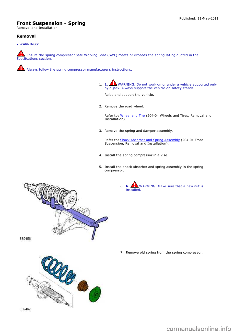
Inst all t he s pring compres s or in a vis e.4.
Inst all t he s hock abs orber and spring as s embl y i n the springcompres s or.5.
6. W ARNING: Make sure t hat a new nut isi ns t alled.6.
Remove old spring from the spring compres s or.7.
Page 229 of 3229
Installation
Inst all t he new s pri ng to the compres s or and compress suffi ci ent ly.
1. 2.
W ARNINGS: Make s ure that a new nut is i ns t alled.
It i s imperat ive that the ti ming marks are
ali gned as s hown in i ll us t rat ion.
T orque: 80 Nm 2.
Releas e t he tens ion from t he spring and damper as sembl y and
remove from t he s pecial t ool .
3.
Remove t he s pring compres s or from a vi s e.
4.
Inst all t he s pring and damper as sembl y.
Refer t o: Shock Abs orber and Spring As s embly (204-01 Front
Sus pens ion, Removal and Inst all at ion).
5.
Inst all t he road wheel.
Refer t o: W heel and Ti re (204-04 W heel s and Tires, Removal and
Inst all at ion).
6.
Page 238 of 3229
Publi s hed: 11-May-2011
Rear Suspension - Rear Wheel Bearing
Removal and Inst all ati on
Special T ool(s)
204-528/2Remover/Ins t al ler, Bus hing
205-725Remover/Ins t al ler, W heel Hub
205-726Remover/Ins t al ler, W heel Hub Bearing
205-728Remover/Ins t al ler, W heel Hub
205-802/5Remover, W heel Hub/Beari ng
Removal
1. W ARNING: Make sure t o s upport the vehicle wit h axles tands .
Rais e and s upport t he vehi cl e.
1.
Remove t he wheel and t ire.
Refer t o: W heel and Ti re (204-04 W heel s and Tires, Removal andInst all at ion).
2.
Remove t he wheel knuckl e.
Refer t o: W heel Knuckle (204-02 Rear Sus pensi on, Removal and
3.
Page 242 of 3229

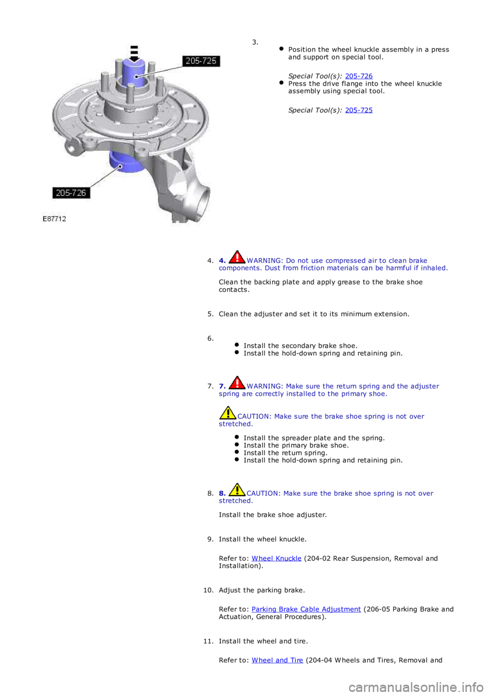
Pos it ion t he wheel knuckl e as sembl y in a pres s
and s upport on s pecial t ool .
Speci al Tool (s ): 205-726 Pres s t he dri ve fl ange into the wheel knuckle
as sembl y us ing s peci al t ool.
Speci al Tool (s ): 205-725 3.
4. W ARNING: Do not use compress ed air t o clean brake
component s. Dus t from fricti on mat erial s can be harmful i f inhaled.
Clean t he backi ng plat e and appl y greas e t o t he brake s hoe
cont acts .
4.
Clean t he adjus t er and s et it to i ts mini mum ext ens ion.
5.
Inst all t he s econdary brake s hoe. Inst all t he hol d-down s pri ng and ret aining pi n.6.
7. W ARNING: Make sure t he ret urn s pri ng and t he adjus ter
s pri ng are correct ly ins tal led t o t he pri mary s hoe. CAUTION: Make s ure the brake shoe s pring i s not over
s tretched.
Inst all t he s preader plat e and t he s pring. Inst all t he pri mary brake shoe.
Inst all t he ret urn s pri ng.
Inst all t he hol d-down s pri ng and ret aining pi n.7.
8. CAUTION: Make s ure the brake shoe s pri ng is not over
s tretched.
Inst all t he brake s hoe adjus ter.
8.
Inst all t he wheel knuckl e.
Refer t o: W heel Knuckle (204-02 Rear Sus pensi on, Removal and
Inst all at ion).
9.
Adjus t t he parking brake.
Refer t o: Parking Brake Cabl e Adjus tment (206-05 Parking Brake and
Actuat ion, General Procedures ).
10.
Inst all t he wheel and t ire.
Refer t o: W heel and Ti re (204-04 W heel s and Tires, Removal and
11.
Page 243 of 3229
Publi s hed: 11-May-2011
Rear Suspension - Front Lower Arm
Removal and Inst all ati on
Removal
1. W ARNING: Make sure t o s upport the vehicle wit h axles tands .
Rais e and s upport t he vehi cl e.
1.
Remove t he wheel and t ire.
Refer t o: W heel and Ti re (204-04 W heel s and Tires, Removal andInst all at ion).
2.
Di scard the bolt .3.
4.
Part ial ly release the bol t for acces s. Cut off the bolt headand wi thdraw in the opposi te direct ion.On ins tall ati on, reverse the orient at ion of t he new bolt .Make s ure the capti ve nut and protecti ve s hi eld from t hes ervice ki t is i nst all ed.
5.
Page 244 of 3229
6.
Installation Inst all t he front lower arm.
1.
2. CAUTION: Nut s and bol ts mus t be ti ght ened wit h t he weight
of t he vehi cl e on t he s us pensi on.
Inst all t he nut s , bol ts and washers, do not t ighten at this st age.
2.
3. CAUTION: Nut s and bol ts mus t be ti ght ened wit h t he weight
of t he vehi cl e on t he s us pensi on.
Support weight of vehi cl e on a jack at the rear hub.
3.
Tight en the nut s and bolt s.
T orque: 175 Nm 4.
5. W ARNING: Make sure t hat a new bolt i s ins tal led.
Inst all t he parking brake cable ret ai ning bolt .
T orque: 10 Nm 5.
Inst all t he rear wheel.
Refer t o: W heel and Ti re (204-04 W heel s and Tires, Removal and
Inst all at ion).
6.
Check and if neces s ary, adjus t the rear wheel ali gnment
7.
Page 245 of 3229
Publi s hed: 11-May-2011
Rear Suspension - Rear Lower Arm
Removal and Inst all ati on
Removal
• NOTE: Removal s t eps in t his procedure may cont ain i nst all ati on det ail s.
1. W ARNING: Do not work on or under a vehi cle s upported onl y
by a jack. Al ways support t he vehi cl e on s afet y s tands .
Rais e and s upport t he vehi cl e.
1.
Remove t he wheel and t ire.
Refer t o: W heel and Ti re (204-04 W heel s and Tires, Removal and
Inst all at ion).
2.
Duri ng ins t al lat ion, do not ti ght en t he nuts and
bolt s unti l the 4 wheel ali gnment procedure has
been carri ed out. T orque:
175 Nm 3.
Installation To i nst all , revers e t he removal procedure.
1.
Carry out the wheel ali gnment procedure.
2.