2006 LAND ROVER FRELANDER 2 instrument panel
[x] Cancel search: instrument panelPage 2613 of 3229
Publ is hed: 11-May-2011
Side Panel Sheet Metal Repairs - A-Pillar Reinforcement
Removal and Installation
Removal
• CAUTIONS:
The A-Pillar reinforcement is DP600, (Dual Phase steel) and must be MIG plug welded to the inner. Spot we lds must
not be used.
Ensure that all welded joints are suitably sealed and waterproofed, particularly in the areas where the original panel
adhesive / sealer cannot be replicated. W here necessary, seal the joints prior to the fitment of outer panels.
• NOTE: The A-Pillar reinforcement is unpicked from the side panel reinforcement 'ring-frame', it is not serviced separately.
• NOTE: There are NVH elements attached inside this panel, they are not serviced on the new panel. If damaged, new
element/s will be required.
1. The A-Pillar reinforcement is replaced in conjunction with:
Front bumper cover
Front fender
Front door
Instrument panel
Windshield glass
A-Pillar outer panel
2. Fo r a d d i t i o na l i nf o rma t i o n re l a t i ng t o t hi s re p a i r p ro ce d ure
please see the following:
Fo r a d d i t i o na l i nf o rma t i o n, re f e r t o : Body and Frame
(501-26
Body Repairs - Vehicle Specific Information and Tolerance
Checks, Description and Operation) /
St a nd a rd W o rks ho p P ra ct i ce s
(100-00 Ge ne ra l I nf o rma t i o n,
Description and Operation).
3. Remove the A-Pillar outer panel.
Fo r a d d i t i o na l i nf o rma t i o n, re f e r t o : A -P i l l a r O ut e r P a ne l
(501-29 Side Panel Sheet Metal Repairs, Removal and
Installation).
Page 2630 of 3229
Publ is hed: 11-May-2011
Side Panel Sheet Metal Repairs - Rocker Panel
Removal and Installation
Removal
CAUTION: The rocker panel must be MIG slot brazed to the rocker panel inner reinforcement, which is DP600, (Dual
Phase steel). MIG plug we lds / spot w elds must not be use d.
• N O T E: T he ro cke r p a ne l i s s e rvi ce d a s a s e p a ra t e w e l d -o n p a ne l .
1. The rocker pane l i s repl ace d i n conjunct i on wi t h:
Front bumper cover
Front fender
Front door
Rear door
2. Fo r a d d i t i o na l i nf o rma t i o n re l a t i ng t o t hi s re p a i r p ro ce d ure
please see the following:
Fo r a d d i t i o na l i nf o rma t i o n, re f e r t o : Body and Frame
(501-26
Body Repairs - Vehicle Specific Information and Tolerance
Checks, Description and Operation) /
St a nd a rd W o rks ho p P ra ct i ce s
(100-00 Ge ne ra l I nf o rma t i o n,
Description and Operation).
3. Remove the fender.
4. Remove the front door.
Fo r a d d i t i o na l i nf o rma t i o n, re f e r t o : Front Door
(501-03 Body
Closures, Removal and Installation).
5. Remove the rear door.
Fo r a d d i t i o na l i nf o rma t i o n, re f e r t o : Rear Door
(501-03 Body
Closures, Removal and Installation).
6. Remove the front road wheel.
Fo r a d d i t i o na l i nf o rma t i o n, re f e r t o : Wheel and Tire
(204-04
Wheels and Tires, Removal and Installation).
7. Re mo ve t he re a r ro a d w he e l .
Fo r a d d i t i o na l i nf o rma t i o n, re f e r t o : Wheel and Tire
(204-04
Wheels and Tires, Removal and Installation).
8. LH side: Remove the hood release handle.
9. Remove the front seat.
Fo r a d d i t i o na l i nf o rma t i o n, re f e r t o : Front Seat
(501-10
Seating, Removal and Installation).
10. Remove the floor console.
Fo r a d d i t i o na l i nf o rma t i o n, re f e r t o : Floor Console
(501-12
Instrument Panel and Console, Removal and Installation).
11. Remove the front door aperture weatherseal.
12. Remove the rear door aperture weatherseal.
13. Remove the cowl side trim panel.
Fo r a d d i t i o na l i nf o rma t i o n, re f e r t o : Cowl Side Trim Panel
(501-05 Int eri or Trim and Ornament at i on, Removal and
Installation).
14. Re mo ve t he B -P i l l a r up p e r t ri m.
Fo r a d d i t i o na l i nf o rma t i o n, re f e r t o : B-Pillar Upper Trim Panel
(501-05 Int eri or Trim and Ornament at i on, Removal and
Installation).
15. Remove the RH & LH B-Pillar lower trims.
Fo r a d d i t i o na l i nf o rma t i o n, re f e r t o : B-Pillar Lower Trim Panel
(501-05 Int eri or Trim and Ornament at i on, Removal and
Installation).
16. Remove the rear quarter trim panel.
Fo r a d d i t i o na l i nf o rma t i o n, re f e r t o : Rear Quarter Trim Panel
(501-05 Int eri or Trim and Ornament at i on, Removal and
Installation).
17. Remove the RH & LH rocker panel inner trims.
18. Remove the rocker panel outer moulding.
19. Remove the back panel inner trim.
20. Remove the rear seat cushion.
Fo r a d d i t i o na l i nf o rma t i o n, re f e r t o : Rear Seat Cushion
(501-10
Seating, Removal and Installation).
21. Remove the front safety belt retractor.
Page 2636 of 3229
Publ is hed: 11-May-2011
Rear End Sheet Metal Repairs - Quarter Panel
Removal and Installation
Removal
CAUTION: The quarter panel must be MIG slot brazed to the rocker panel inner reinforcement, which is DP600, (Dual
Phase steel). MIG plug we lds / spot w elds must not be use d in this are a.
• NOTE: The quarter panel is serviced as a separate weld-on panel.
• NOTE: There are NVH elements inside this panel, they are not serviced on the new panel. If damaged, a new element
will be required.
1. The quarter panel is replaced in conjunction with:
Rear bumper cover
Rear door
Quarter glass
Headliner
2. Fo r a d d i t i o na l i nf o rma t i o n re l a t i ng t o t hi s re p a i r p ro ce d ure
please see the following:
Fo r a d d i t i o na l i nf o rma t i o n, re f e r t o : Body and Frame
(501-26
Body Repairs - Vehicle Specific Information and Tolerance
Checks, Description and Operation) /
St a nd a rd W o rks ho p P ra ct i ce s
(100-00 Ge ne ra l I nf o rma t i o n,
Description and Operation).
3. Re move t he re a r bumpe r co ve r.
Fo r a d d i t i o na l i nf o rma t i o n, re f e r t o : Rear Bumper
(501-19
Bumpe rs , Re mo va l a nd Ins t a l l a t i on).
4. Remove the rear door.
Fo r a d d i t i o na l i nf o rma t i o n, re f e r t o : Rear Door
(501-03 Body
Closures, Removal and Installation).
5. Remove the headliner.
Fo r a d d i t i o na l i nf o rma t i o n, re f e r t o : Headliner - Vehicles
Without: Tilting Roof Opening Panel (501-05 Int eri or Tri m and
Ornamentation, Removal and Installation) /
Headliner - Vehicles With: Tilting Roof Opening Panel
(501-05
Int erior Trim and Ornamentat ion, Removal and Installat ion).
6. Re mo ve t he re a r d o o r s t ri ke r f ro m t he C-P i l l a r.
7. Remove the roof moulding, front and rear sections.
8. Re mo ve t he s i d e a i r curt a i n mo d ul e .
Fo r a d d i t i o na l i nf o rma t i o n, re f e r t o : Si d e A i r Curt a i n Mo d ul e
(501-20B Suppl ement al Res t rai nt Sys t em, Removal and
Installation).
9. Remove the rear quarter glass.
Fo r a d d i t i o na l i nf o rma t i o n, re f e r t o : Rear Quarter Window
Gl a s s (501-11 Glass, Frames and Mechanisms, Removal and
Installation).
10. Remove the front seat.
Fo r a d d i t i o na l i nf o rma t i o n, re f e r t o : Front Seat
(501-10
Seating, Removal and Installation).
11. Remove the floor console.
Fo r a d d i t i o na l i nf o rma t i o n, re f e r t o : Floor Console
(501-12
Instrument Panel and Console, Removal and Installation).
12. Remove the RH & LH rocker panel inner trims.
13. Remove the rear seat cushion.
Fo r a d d i t i o na l i nf o rma t i o n, re f e r t o : Rear Seat Cushion
(501-10
Seating, Removal and Installation).
14. Re mo ve t he re a r ca rp e t s e ct i o n.
15. Remove the rear safety belt retractor.
Fo r a d d i t i o na l i nf o rma t i o n, re f e r t o : Rear Safety Belt Retractor
(501-20A Safe t y Bel t Sys t em, Removal and Ins t al l at i on).
16. Remove the liftgate aperture weatherseal.
17. Remove the forced air extraction grille.
18. Remove the rear wheel and tire.
Fo r a d d i t i o na l i nf o rma t i o n, re f e r t o : Wheel and Tire
(204-04
Wheels and Tires, Removal and Installation).
19. Remove the rocker panel outer moulding.
20. Release and lay aside the wiring harness along the inner
Page 2723 of 3229

Contents
3
R
Quick start
QUICK START ................................................... 7
Filling station information
FILLING STATION INFORMATION................... 33
Introduction
SYMBOLS GLOSSARY .................................... 35
LABEL LOCATIONS ......................................... 35
HEALTH AND SAFETY ..................................... 36
DATA RECORDING.......................................... 37
DISABILITY MODIFICATIONS ......................... 37
PARTS AND ACCESSORIES ............................ 37
Keys and remote controls
USING THE KEY .............................................. 40
GENERAL INFORMATION ON RADIO
FREQUENCIES ................................................ 40
USING THE REMOTE CONTROL ..................... 41
Locks
LOCKING AND UNLOCKING ............................ 44
Alarm
ARMING THE ALARM ..................................... 45
DISARMING THE ALARM ............................... 46
Seats
SITTING IN THE CORRECT POSITION ............ 47
MANUAL SEATS ............................................. 48
ELECTRIC SEATS ............................................ 49
HEAD RESTRAINTS ........................................ 51
REAR SEATS................................................... 51
HEATED SEATS............................................... 53
Seat belts
PRINCIPLE OF OPERATION ............................ 54
SEAT BELT REMINDER ................................... 55
FASTENING THE SEAT BELTS ........................ 56
SEAT BELT HEIGHT ADJUSTMENT................. 56
USING SEAT BELTS DURI NG PREGNANCY .... 57
Supplementary restraints system
PRINCIPLE OF OPERATION ............................ 58
AIRBAG WARNING LAMP ............................... 61
DISABLING THE PASSENGER AIRBAG ........... 62
AIRBAG SERVICE INFORMATION ................... 63
Child safety
CHILD SEATS ................................................. 64
BOOSTER CUSHIONS ..................................... 66
ISOFIX ANCHOR POINTS................................ 67
CHILD SAFETY LOCKS ................................... 69
Steering wheel
ADJUSTING THE STEERING WHEEL .............. 70
AUDIO CONTROL ........................................... 70
Lighting
LIGHTING CONTROL ...................................... 72
FRONT FOG LAMPS........................................ 72
REAR FOG LAMPS.......................................... 73
ADJUSTING THE HEADLAMPS....................... 73
HEADLAMP LEVELLING ................................. 73
HAZARD WARNING FLASHERS...................... 74
ADAPTIVE FRONT LIGHTING SYSTEM (AFS) . 74
DIRECTION INDICATORS ............................... 75
INTERIOR LAMPS .......................................... 76
APPROACH LAMPS ........................................ 76
CHANGING A BULB ........................................ 77
BULB SPECIFICATION CHART ........................ 86
Wipers and washers
WINDSCREEN WIPERS .................................. 87
RAIN SENSOR ................................................ 87
WINDSCREEN WASHERS............................... 88
HEADLAMP WASHERS................................... 88
REAR WINDOW WIPER AND WASHERS ........ 89
ADJUSTING THE WINDSCREEN WASHER JETS .
89
CHECKING THE WIPER BLADES .................... 90
CHANGING THE WIPER BLADES.................... 90
Windows and mirrors
ELECTRIC WINDOWS ..................................... 93
EXTERIOR MIRRORS ..................................... 94
ELECTRIC EXTERIOR MIRRORS .................... 95
INTERIOR MIRROR ........................................ 96
Instruments
INSTRUMENT PANEL OVERVIEW .................. 97
Information displays
TRIP COMPUTER ........................................... 99
INFORMATION MESSAGES ............................ 99
Page 2739 of 3229
19
Quick start
R
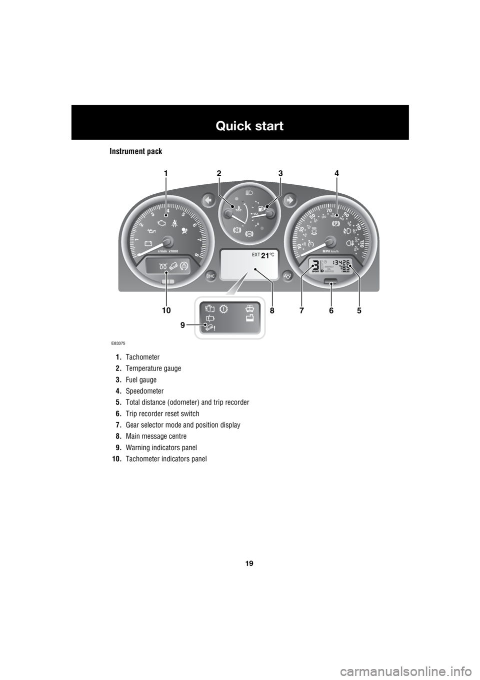
Instrument pack
1. Tachometer
2. Temperature gauge
3. Fuel gauge
4. Speedometer
5. Total distance (odometer) and trip recorder
6. Trip recorder reset switch
7. Gear selector mode and position display
8. Main message centre
9. Warning indicators panel
10. Tachometer indi cators panel
EXT C21
E83375
567108
9
1423
Page 2759 of 3229
39
Introduction
R
Airbag system
To prevent malfunction of the airbag system
always consult a Land Rover Dealer/
Authorised Repairer before fitting any of the
following:
• Electronic equipment such as a mobile
phone, two-way radio or in-car
entertainment system.
• Accessories attached to the front of the
vehicle.
• Any modification to the front of the vehicle.
• Any modification involving the removal or
repair of any wiring or component in the
vicinity of any of the airbag system
components, including the steering wheel,
steering column, instrument or facia
panels.
• Any modification to th e facia panels or
steering wheel.
After-sales service
The After Sales Parts service is of paramount
importance, both in th e UK and across the
world. In the UK there are over 100 authorised
Land Rover Dealers/Authorised Repairers, all
computer linked for rapid ordering of parts and
accessories.
In addition, with franch ised representation in
over 100 countries worldwide, Land Rover are
able to support your vehicle wherever you go.
Travelling abroad
In certain countries, it is a legal requirement to
fit parts made to the vehicle manufacturers'
specification.
Owners should ensure that any parts or
accessories fitted to the vehicle while travelling
abroad will also conform to the legal
requirements of their own country when they
return home.
WARNING
The components that make up the
airbag system are sensitive to
electrical or physical interference,
either of which coul d easily damage the
system and cause inadvertent operation or a
malfunction of th e airbag module.
E84193
Page 2817 of 3229
97
Instruments
R
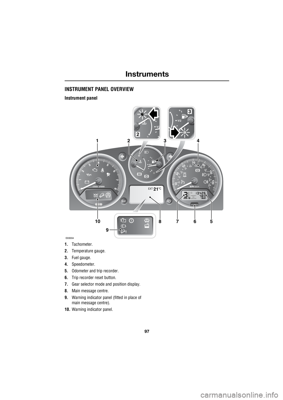
InstrumentsINSTRUMENT PANEL OVERVIEW
Instrument panel
1. Tachometer.
2. Temperature gauge.
3. Fuel gauge.
4. Speedometer.
5. Odometer and trip recorder.
6. Trip recorder reset button.
7. Gear selector mode and position display.
8. Main message centre.
9. Warning indicator panel (fitted in place of
main message centre).
10. Warning indicator panel.
EXT C21
E83004
567108
9
1423
2
3
Page 2818 of 3229
Instruments
98
L
Tachometer
Indicates engine spee d in revolutions per
minute (RPM) x 1000.
Temperature gauge
If the pointer moves onto the red line and the
red warning indicator illu minates severe engine
damage can occur.
If the engine overheats, stop the vehicle as
soon as safety pe rmits. Switch the engine off
and allow it to cool down. If the problem
reoccurs, seek qualified assistance before
continuing.
Note: If engine temperatur e rises to the point
where overheating may occur, there may be a
noticeable reduction in engine power, and the
air conditioning may cease operation. This is a
normal operating strate gy to reduce load on
the engine and assist with cooling.
Fuel gauge
Once the fuel level has dropped to the point
where the range is approximately 80 km (50
miles) the low fuel warning indicator will
illuminate.
As a reminder for the location of the fuel filler,
there is an arrow next to the fuel pump symbol
which points to the releva nt side of the vehicle.
Speedometer
Indicates road speed. Odometer
Indicates the total distance which the vehicle
has travelled.
Trip recorder
Indicates the distance travelled since the last
reset, and can be used to measure the distance
of individual journeys.
Trip recorder reset button
Resets the distance shown on the trip recorder
to zero.
Note: Once the trip recorder has been reset to
zero, the previously recorded distance will be
lost.
Gear selector mode and positiondisplay
Displays the currently selected gear on
vehicle's fitted with automatic transmission.
Main message centre
Displays warning, and information messages.
See INFORMATION MESSAGES (page 99).
Warning indicator panel (fitted in place of
main message centre)
If a main message centre is not fitted, the
warning indicator pane l will provide system
status information.
Warning indicator panel
The warning indicator panel will provide
system status information.
CAUTION
Serious engine damage can occur if the
vehicle is driven whilst the engine is
overheating.
CAUTION
Never allow the vehicle to run out of
fuel. The resulting mis-fire may cause
serious damage to the catalytic
convertor.