2006 LAND ROVER FRELANDER 2 tire pressure
[x] Cancel search: tire pressurePage 288 of 3229
Publi s hed: 11-May-2011
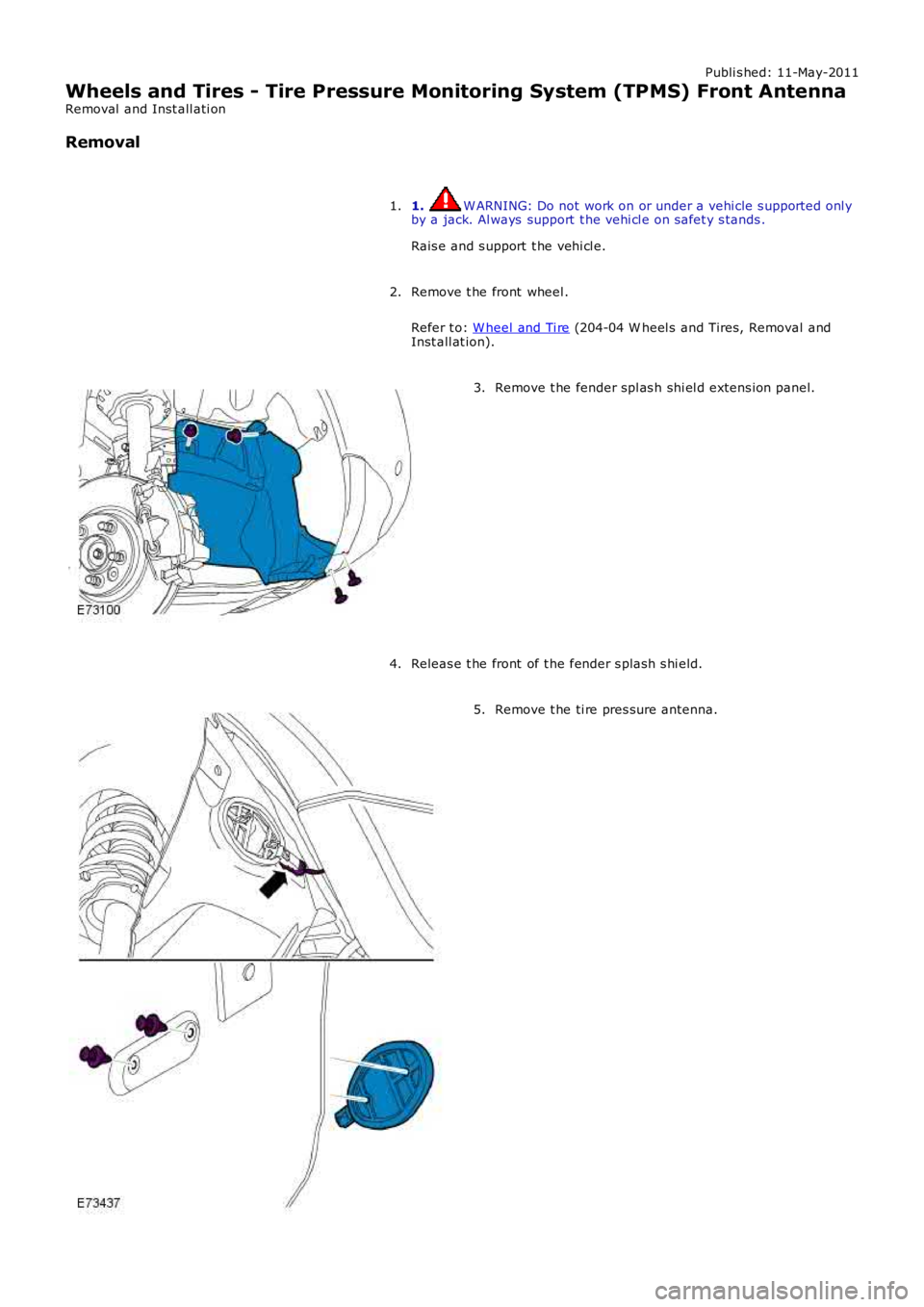
Wheels and Tires - Tire Pressure Monitoring System (TPMS) Front Antenna
Removal and Inst all ati on
Removal
1. W ARNING: Do not work on or under a vehi cle s upported onl yby a jack. Al ways support t he vehi cl e on s afet y s tands .
Rais e and s upport t he vehi cl e.
1.
Remove t he front wheel .
Refer t o: W heel and Ti re (204-04 W heel s and Tires, Removal andInst all at ion).
2.
Remove t he fender spl as h shi el d extens ion panel.3.
Releas e t he front of t he fender s plas h s hi eld.4.
Remove t he ti re pres sure antenna.5.
Page 290 of 3229
Publi s hed: 11-May-2011
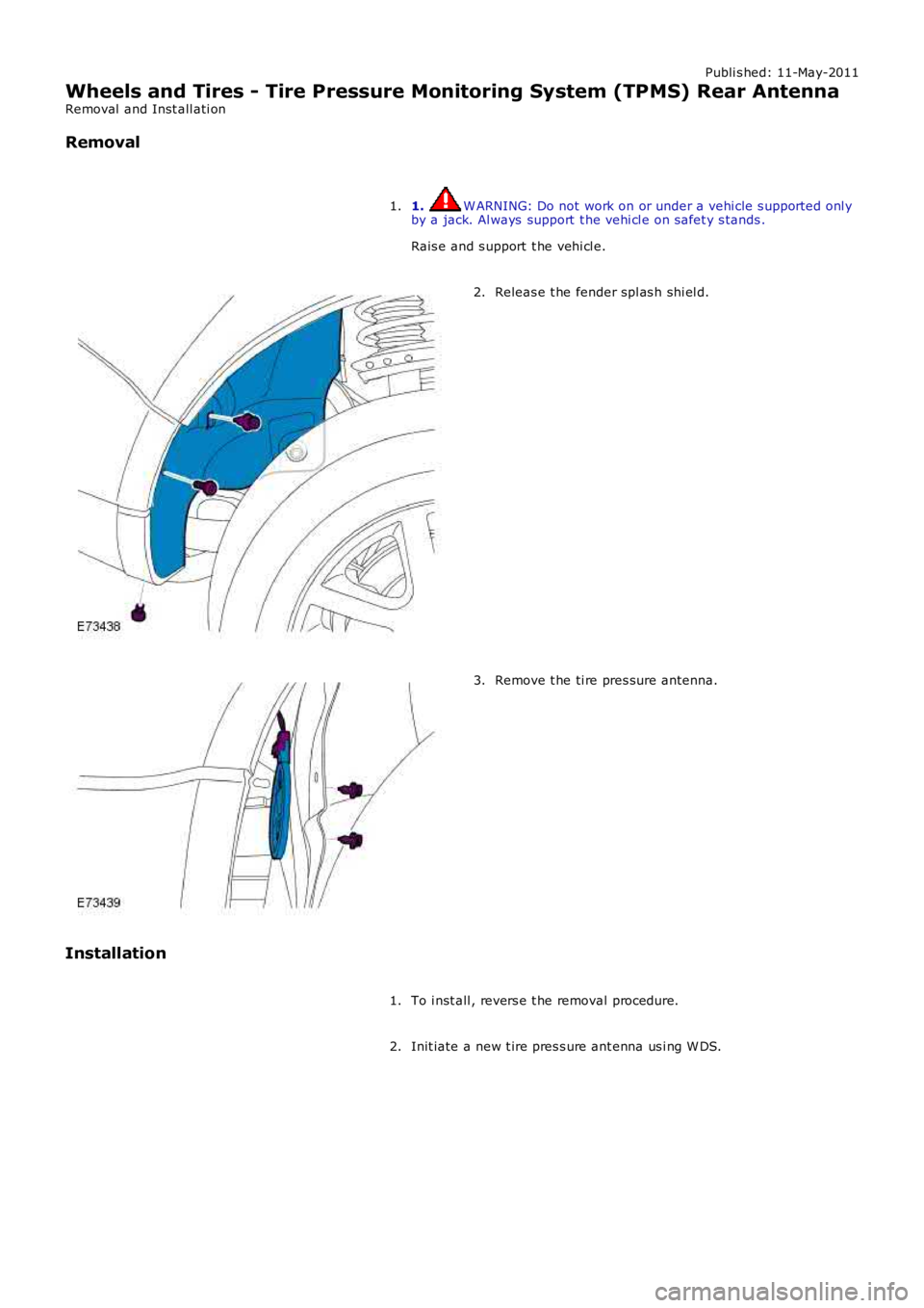
Wheels and Tires - Tire Pressure Monitoring System (TPMS) Rear Antenna
Removal and Inst all ati on
Removal
1. W ARNING: Do not work on or under a vehi cle s upported onl yby a jack. Al ways support t he vehi cl e on s afet y s tands .
Rais e and s upport t he vehi cl e.
1.
Releas e t he fender spl as h shi el d.2.
Remove t he ti re pres sure antenna.3.
Installation
To i nst all , revers e t he removal procedure.1.
Init iate a new t ire pres s ure ant enna us i ng W DS.2.
Page 1771 of 3229
Vehicle i n power mode 6 (all vehi cles except NAS vehicles )Vehicle i n power mode 6 for 75 s econds (NAS vehicl es onl y)Vehicle s peed is greater t han 6 mph (10 kph)Dri vers s afet y belt not s ecured in i ts buckleLarge pas senger det ect ed i n front pas s enger s eat wit h an uns ecured safety bel t.
The warni ng indicator wi ll flas h at a frequency of 2 Hz while accompani ed by a chime from the i nst rument clus ter for 10s econds. Thi s is foll owed by a 10 s econd period where the warning i ndicat or is permanent ly ill uminat ed and the s ounder i ss il ent . Thi s 10 s econd cycle wi ll be repeat ed for a maxi mum of 190 seconds or any of t he condit ions l is t ed above cease toexis t.
Supplemental Restraint System Warning Indicator
The Suppl ement al Rest rai nt Sys tem (SRS) warning i ndi cat or is i lluminated on recei pt of a medium s peed CAN bus si gnalfrom the CJB. The si gnal originat es in t he RCM whi ch monit ors t he condi ti on of the SRS and ill uminat es the red warni ngindicat or accordingly.
The SRS warni ng indicator i s il lumi nat ed by t he RCM for a 6 s econd bul b check when the vehicle firs t ent ers power mode 6.If a fault is detect ed wit h t he indicator, the ins trument cl us t er returns a medi um speed CAN bus s ignal vi a t he CJB to theRCM and a Diagnos t ic Troubl e Code (DTC) i s s tored in the RCM's memory. The mes s age 'SrS' wi ll als o be di spl ayed i n t heodometer.For addit ional informat ion, refer t o: Informat ion and Mes s age Cent er (413-08 Informat ion and Mes s age Cent er, Des cript ionand Operat ion).
Left and Right Hand Turn Signal Indicators
The green l eft and right hand turn s ignal i ndicat ors are i ll uminated on recei pt of medium speed CAN bus s i gnals from t heCJB. The CJB provi des a CAN bus s ignal wit h one of t he foll owing values :
0 - LH st eeri ng col umn mul ti -funct ion s wit ch in the central pos it ion1 - LH st eeri ng col umn mul ti -funct ion s wit ch in the LH turn posi ti on2 - LH st eeri ng col umn mul ti -funct ion s wit ch in the RH turn pos it ion3 - Hazard fl as hers reques t ed.
If the vehicle is i n power mode 6 t he ins trument cl ust er wil l fl as h the appropri ate turn s ignal i ndicat or if a medium speedCAN bus s ignal is recei ved wit h a value of 1 or 2. Medi um s peed CAN bus s ignals wi th a value of 3 wi ll acti vat e both theLH and RH turn s ignal i ndicat ors si mult aneous ly i rrespecti ve of power mode.
W hen acti vat ed, the l eft and right hand turn s ignal indicators wil l be accompanied by 'ti ck t ock' chimes from t he ins trumentclus ter s ounder.
Brake Warning Indicator
EBA and EBD warnings are trans mi tt ed t o t he CJB from t he ABS module over t he high s peed CAN bus . Thes e s ignals arerel ayed t o t he i ns t rument clus ter on t he medium s peed CAN bus and wil l act ivate the brake warning i ndicat or when t hevehi cl e i s in power mode 6. If an EBA warni ng is request ed, the i ndi cat or wil l ill uminat e in an amber color. If an EBDwarni ng is reques t ed, t he indi cat or will i ll uminate in a red color.
Low brake flui d level warnings are als o t rans mit t ed to the i nst rument clus t er from the CJB on the medi um s peed CAN bus .The s ignal origi nat es in the ABS modul e which recei ves a hardwired input from the brake flui d level s ens or. If a l ow brakefl uid warning i s reques ted, the indicator wil l il lumi nat e i n a red col or when the vehicle is i n power mode 6.
The brake warni ng indi cat or i s als o s ubject t o a 3 second bul b check when the vehicle firs t ent ers power mode 6. Theindicat or wi ll i lluminate in a amber color for 1.5 s econds t hen a red col or for 1.5 s econds .
High Eng ine Coolant Temperature Warning Ind icator
The red hi gh Engine Coolant Temperature (ECT) warning i ndi cat or is control led by the engine t emperat ure gage s oft ware(see above).
Headlamp High Beam Indicator
The blue headlamp hi gh beam i ndi cat or is i ll uminated on recei pt of a medium s peed CAN bus si gnal from the CJB. Thes ignal origi nat es in the l ight s wit ch module and i s t ransmit ted t o t he CJB over t he LIN bus. The i nst rument clus t er will onlyil lumi nat e t he headl amp high beam indicator when t he vehicle i s in power mode 6 and t he LH s teeri ng column mul ti -functi on s wit ch is moved t o t he high beam pos i ti on.
Tire Pressure Monitoring System Indicator
The Tire Pres s ure Moni tori ng Syst em (TPMS) indicator i s cont rol led by t he ins t rument clus ter on receipt of medium s peedCAN bus s ignals from t he CJB. The s ignal ori gi nates i n t he TPMS module. The indicator i s il lumi nat ed in an amber col or fora 3 second bulb check by the TPMS modul e when t he vehi cl e enters power mode 6. If t he indicator remains i lluminated orfl ashes after t he engi ne is st art ed or when dri vi ng, the TPMS has developed a faul t. The t ire pres s ures s houl d bemonit ored manuall y unti l the fault is recti fi ed.For addit ional informat ion, refer t o: W heels and Ti res (204-04 W heels and Tires , Des cript ion and Operat ion).
Anti-lock Brake System Warning Indicator
The Anti -l ock Brake Sys t em (ABS) warning i ndicat or is controll ed by the ABS module whi ch trans mi ts a high s peed CAN busmes s age to t he CJB. The CJB relays t he mes sage t o t he i ns t rument clus ter over the medi um s peed CAN bus . The warningindicat or i s il lumi nat ed i n an amber col or for 3 s econds for a bulb check by the ABS modul e when t he vehi cl e enters powermode 6. If the warning i ndi cat or remains ill uminat ed or ill uminat es when drivi ng, an ABS fault has occurred and t he ABSfuncti on wil l not be avai lable.
Duri ng the bul b check, if t he warni ng indicator comes on for 0.5 s econd, t hen goes off for 0.5 second and is then
Page 1790 of 3229
This group of mess ages have a direct effect on the driving abi li ty and s afet y of t he vehi cl e, 'ENGINE SY STEM FAULT' forexampl e. Thi s mes s age woul d requi re an immedi at e react ion from the driver in res ponse t o t he mes s age. Pri ori ty 1mes s ages wi ll als o be accompani ed by t he appropriat e warni ng indicat or flas hing and a cont inuous chime from theins t rument clus ter. If more t han one priorit y 1 mes s age is present , each mes s age is di s pl ayed in t urn at 3 s econdint ervals .
Priority Group 2
This group of mess ages do not direct ly affect the driving abi lit y or s afet y of the vehicle, 'CHECK BRAKE PADS' for example.This mes s age mus t be noted by t he driver and the cause recti fi ed as s oon as pos s ibl e. Each of thes e mes s ages isdis played once when power mode 6 is ent ered or when t he faul t occurs for a predetermined t ime peri od. Thes e mes sagescan be recall ed by the driver by pres s ing t he t ri p res et butt on for more t han 3 s econds .
Priority Group 3
This group of mess ages rel at e t o l ow pri ori ty mes s ages , 'LOW W ASHER FLUID' for exampl e. Depending on the mes s age,s ome mes s ages are only s hown at t he end of a journey to avoid annoyance to t he driver. The mes s ages wi ll beaccompanied by a chi me when t he igni ti on is s wi tched off t o alert the driver to their presence.
MESSAGE LIST
Mes sages are dis played in a language appropriat e for t he market s peci fi cat ion of t he vehi cl e. The language can be changedif requi red us ing the Land Rover approved diagnos ti c sys t em.
• NOTE: The li s t bel ow i s s hown in al phabeti cal order.
MessageO ther WarningsReasonAction
BONNET OPENNoneHood open or not fully cl osedCl ose hoodCHECK ALL TY REPRESSURESAmber Ti re Pres sureMonit oring Sys tem(TPMS) indi cat oril lumi nat ed
Advi sory mes s age. Low pres s ure warningli mit reached i n more than 1 wheel i n lows peed mode or warning l imi t reached in anyrunning wheel and no locati on s pecified byTPMS.For addit ional informati on, refer t o: W heelsand Tires (204-04 W heel s and Tires,Descripti on and Operat ion).
Check all t ire pres s ures andadjust accordingly
CHECK ALL TY REPRESSURES FRONT LEFTLOW
Amber TPMS indicatoril lumi nat edLow pres s ure warning l imi t reached in frontleft ti re i n l ow s peed modeCheck t ire pres s ure andadjust accordingly
CHECK ALL TY REPRESSURES FRONTRIGHT LOW
Amber TPMS indicatoril lumi nat edLow pres s ure warning l imi t reached in frontri ght t ire i n low s peed modeCheck t ire pres s ure andadjust accordingly
CHECK ALL TY REPRESSURES REAR LEFTLOW
Amber TPMS indicatoril lumi nat edLow pres s ure warning l imi t reached in rearleft ti re i n l ow s peed modeCheck t ire pres s ure andadjust accordingly
CHECK ALL TY REPRESSURES REAR RIGHTLOW
Amber TPMS indicatoril lumi nat edLow pres s ure warning l imi t reached in rearri ght t ire i n low s peed modeCheck t ire pres s ure andadjust accordingly
CHECK SPARE TY REPRESSUREAmber TPMS indicatoril lumi nat ed for 20s econds and agai n ats ubs equent i gni ti oncycles
Low pres s ure warning l imi t reached in s pareti reCheck t ire pres s ure andadjust accordingly
CRANKING W ILLCOMMENCE AFTER GLOWPERIOD
Glow pl ug indi cat oril lumi nat edAmbient air t emperature below 0ºC (32ºF)None
CRUISE CONTRO L NOTPERMITTEDNoneVehi cl e operat ing paramet ers out si dethreshold for s peed cont rol operati onNone
DPF FULLHandbook s ymbolil lumi nat ed inmes sage center
Dies el parti cul at e fil ter requi res regenerat ingFor addit ional i nformati on,refer t o: Exhaus t Sys t em(309-00B Exhaus t Sys tem -TD4 2.2L Di es el,Des cri pti on and Operati on).DPF FULL VISIT DEALERNoneRegenerat ion of t he dies el parti cul at e fil terwas unsucces s fulUse the Land Roverapproved di agnos ti csys tem t o forceregenerati on of the di es elparti cul at e fil ter.
DRIVER DOOR OPENNoneDri vers door open or not ful ly clos edNone
DSC SW ITCHED OFFAmber Dynami cStabil it y Control (DSC)indicator i lluminated
Sys t em not avai lable due to DSC s wit ched offby dri verPress DSC s wit ch toreact ivat e s ys t em
ECO STOP/START FAULTTel l-tal e li ght in t heEco swi tchext inguis hed
Stop/St art not avai lable due to sys tem ors ub-s ys t em failureConnect Land Roverapproved di agnos ti csys tem t o diagnos e fault
ECO STOP/START O FFTel l-tal e li ght in t heEco swi tchext inguis hed
The Eco swi tch has been pres s edIf requi red, pres s the Ecoswi tch t o react ivate theSt op/St art s yst em
ECO STOP/START O NTel l-tal e li ght in t heEco swi tch i ll uminatedThe s ys t em has been s wit ched off and thenlat er s wi tched on wi thin the same ignit ioncycle
If requi red, pres s the Ecoswi tch t o deact ivat e t heSt op/St art s yst em
Page 1793 of 3229
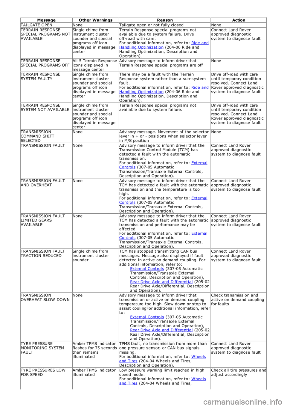
MessageO ther WarningsReasonAction
TAILGATE OPENNoneTai lgat e open or not fully cl osedNone
TERRAIN RESPONSESPECIAL PROGRAMS NOTAVAILABLE
Single chime fromins trument cl ust ers ounder and specialprograms off icondis played in mess agecent er
Terrai n Res pons e s peci al programs notavai lable due t o s ys tem fai lure. Driveoff-road wit h care.For addit ional informati on, refer t o: Ride andHandl ing Opt imi zat ion (204-06 Ri de andHandl ing Opt imi zat ion, Des cript ion andOperati on).
Connect Land Roverapproved di agnos ti csys tem t o diagnos e fault
TERRAIN RESPONSESPECIAL PROGRAMS OFFAll 5 Terrain Res ponseicons dis played inmes sage center
Advi sory mes s age to inform driver thatTerrai n Res pons e s peci al programs are offNone
TERRAIN RESPONSESY STEM FAULTYSingle chime fromins trument cl ust ers ounder and specialprograms off icondis played in mess agecent er
There may be a faul t wit h t he Terrai nRespons e s ys t em rather than a s ub-s ys t emfault .For addit ional informati on, refer t o: Ride andHandl ing Opt imi zat ion (204-06 Ri de andHandl ing Opt imi zat ion, Des cript ion andOperati on).
Drive off-road wit h careunt il t emporary condit ionres ol ved. Connect LandRover approved di agnos t icsys tem t o diagnos e fault
TERRAIN RESPONSESY STEM NOT AVAILABLESingle chime fromins trument cl ust ers ounder and specialprograms off icondis played in mess agecent er
Terrai n Res pons e s peci al programs notavai lable due t o s ys tem fai lure.Drive off-road wit h careunt il t emporary condit ionres ol ved. Connect LandRover approved di agnos t icsys tem t o diagnos e fault
TRANSMISSIONCOMMAND SHIFTSELECTED
NoneAdvi sory mes s age. Movement of t he s electorlever in + or - posi ti ons when sel ect or leverin M/S pos it ion
None
TRANSMISSION FAULTNoneAdvi sory mes s age to inform driver that t heTrans mis s ion Control Modul e (TCM) hasdet ected a fault wi th the aut omati ctransmis si on.For addit ional informati on, refer t o: Ext ernalCont rol s (307-05 Automat icTrans mis s ion/Trans axle Ext ernal Cont rols ,Descripti on and Operat ion).
Connect Land Roverapproved di agnos ti csys tem t o diagnos e fault
TRANSMISSION FAULTAND OVERHEATNoneAdvi sory mes s age to inform driver that t heTCM has detected a fault wit h t he aut omati ctransmis si on and t he temperat ure is t oohigh.For addit ional informati on, refer t o: Ext ernalCont rol s (307-05 Automat icTrans mis s ion/Trans axle Ext ernal Cont rols ,Descripti on and Operat ion).
Connect Land Roverapproved di agnos ti csys tem t o diagnos e fault
TRANSMISSION FAULTLIMITED GEARSAVAILABLE
NoneAdvi sory mes s age to inform driver that t heTCM has detected a fault wit h t he aut omati ctransmis si on and performance may beaffect ed.For addit ional informati on, refer t o: Ext ernalCont rol s (307-05 Automat icTrans mis s ion/Trans axle Ext ernal Cont rols ,Descripti on and Operat ion).
Connect Land Roverapproved di agnos ti csys tem t o diagnos e fault
TRANSMISSION FAULTTRACTION REDUCEDSingle chime fromins trument cl ust ers ounder
TCM has s topped t rans mit ti ng CAN busmes sages . Mess age als o di spl ayed i f faultdet ected i n acti ve on demand coupli ng. Foraddi ti onal i nformat ion, refer to:Ext ernal Cont rol s (307-05 Aut omati cTransmis si on/Trans axl e ExternalCont rols , Des cript ion and Operat ion),Rear Drive Axle and Different ial (205-02Rear Drive Axle/Different ial, Des cript ionand Operati on).
Connect Land Roverapproved di agnos ti csys tem t o diagnos e fault
TRANSMISSIONOVERHEAT SLOW DOW NNoneAdvi sory mes s age to inform driver thattransmis si on or act ive on demand coupli ngtemperat ure too hi gh. Sl ow down or s top t oass i st cooli ngFor addi ti onal i nformat ion, referto:Ext ernal Cont rol s (307-05 Aut omati cTransmis si on/Trans axl e ExternalCont rols , Des cript ion and Operat ion),Rear Drive Axle and Different ial (205-02Rear Drive Axle/Different ial, Des cript ionand Operati on).
Check t rans mis s ion andact ive on demand coupl ingfor fault s
TY RE PRESSUREMONITORING SY STEMFAULT
Amber TPMS indicatorfl ashes for 75 secondsthen remainsil lumi nat ed
TPMS fault , no t rans mis s ion from more t hanone pres sure s ensor, or CAN bus si gnal smis s ing.For addit ional informati on, refer t o: W heelsand Tires (204-04 W heel s and Tires,Descripti on and Operat ion).
Connect Land Roverapproved di agnos ti csys tem t o diagnos e fault
TY RE PRESSURES LOWFOR SPEEDAmber TPMS indicatoril lumi nat edLow pres s ure warning l imi t reached in hi ghs peed mode.For addit ional informati on, refer t o: W heelsand Tires (204-04 W heel s and Tires,
Check all t ire pres s ures andadjust accordingly
Page 2774 of 3229
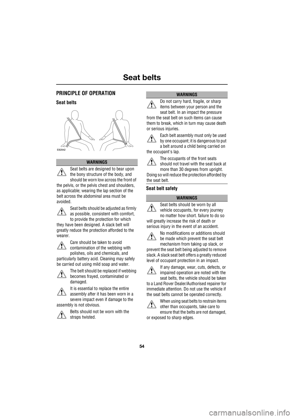
Seat belts
54
L
Seat beltsPRINCIPLE OF OPERATION
Seat belts Seat belt safety
WARNINGS
Seat belts are designed to bear upon
the bony structure of the body, and
should be worn low across the front of
the pelvis, or the pelv is chest and shoulders,
as applicable; wearing the lap section of the
belt across the abdominal area must be
avoided.
Seat belts should be adjusted as firmly
as possible, consistent with comfort,
to provide the protection for which
they have been design ed. A slack belt will
greatly reduce the protec tion afforded to the
wearer.
Care should be taken to avoid
contamination of the webbing with
polishes, oils and chemicals, and
particularly battery acid . Cleaning may safely
be carried out using mild soap and water.
The belt should be replaced if webbing
becomes frayed, contaminated or
damaged.
It is essential to replace the entire
assembly after it has been worn in a
severe impact even if damage to the
assembly is not obvious.
Belts should not be worn with the
straps twisted.
E82942
Do not carry hard, fragile, or sharp
items between your person and the
seat belt. In an impact the pressure
from the seat belt on such items can cause
them to break, which in turn may cause death
or serious injuries.
Each belt assembly must only be used
by one occupant; it is dangerous to put
a belt around a child being carried on
the occupant's lap.
The occupants of the front seats
should not travel with the seat back at
more than 30 degrees from upright.
Doing so will reduce the protection afforded by
the seat belt.
WARNINGS
Seat belts should be worn by all
vehicle occupants, for every journey
no matter how short. failure to do so
will greatly increase the risk of death or
serious injury in the event of an accident.
No modifications or additions should
be made which prevent the seat belt
mechanism from taking up slack, or
prevent the seat belt being adjusted to remove
slack. A slack seat belt offers a greatly reduced
level of occupant prot ection in an impact.
If any damage, wear, cuts, defects, or
impaired operation are noted with the
seat belts, the vehicle should be taken
to a Land Rover Dealer/Authorised repairer for
immediate attention. Do not use the vehicle if
the seat belts cannot be operated correctly.
When using seat belts to restrain items
other than occupants, take care to
ensure that the belts are not damaged,
or exposed to sharp edges.
WARNINGS
Page 2999 of 3229
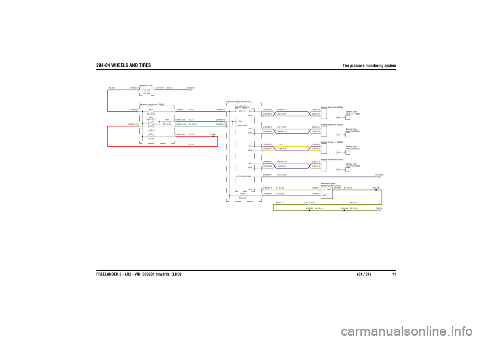
204-04 WHEELS AND TIRES
Tire pressure monitoring system
FREELANDER 2 - LR2 - VIN: 000201 onwards (LHD)(01 / 01) 11
204-04 WHEELS AND TIRES Tire pressure monitoring system
RD,0.5
RD,25.0
RD,0.5BU,4.0GN-VT,0.75RD,6.0
BK,35.0
BK-YE,6.0BK-YE,1.5
BK-YE,0.5
GY-RD,0.5BK-YE,1.5GY-BN,0.5
BK-YE,2.5
BK-VT,0.75BN-WH,0.75BU-BN,0.75YE,0.75VT-BN,0.75GY-VT,0.75BN-GN,0.75BU-OG,0.75BN-YE,0.75
Module (CEM) (D316) Central Electronics
Central junction-box (P101)
Battery junction-box (P147)
Ignition (R211)Relay-RE7
POWER MINIFE33
5.0 AmpsFE17
60.0 Amps
FE41
20.0 Amps
Battery (P100)12.0 Volts
frequency (RF) (T203) Receiver-Radio-
FS21
5.0 Amps
C22C-7 C22D-7
Front-RH (T292) Sensor-Tyre-Front-LH (T291)
Sensor-Tyre-Rear-RH (T294)
Sensor-Tyre-Rear-LH (T293)
Sensor-Tyre-
Initiator-Rear-LH (M284)Initiator-Front-LH (M282)Initiator-Front-RH (M281)Initiator-Rear-RH (M283)
ELECTRONIC GNDIGN RELAYBATT AIGN
C1BB01A-107
C1BB01A-98C1BB01A-92C1BB01A-106C1BB07G-1
C1BB01B-1
S1BB33
C1BP02A-65C1BP02A-45C1BP02G-1
C1D134B-1
C1DC02A-1
G1D108A-1
S2D139B
C1BP02H-15C1BP02H-5
LIN 0
C3PL56-1
LINC3PL56-3
BATT
S2D139A
C3PL56-2
GND
S9D139BG6D139-1
SIG
C1BP02A-33C1BP02A-22C1BP02A-34C1BP02A-21C1BP02A-54
GNDGNDSIG
C1BP02B-4C1BP02B-16C1BP02B-3C1BP02B-15
SIGGNDSIGGND
C1MC40-1C1MC41-2C1MC41-1C1MC40-2C3MC43-2C3MC43-1C3MC42-2C3MC42-1
G1D132B-1
Page 3100 of 3229

08/20085
ABBREVIATIONS
........................................................................................................................................................................................................ 7
USING THIS PUBLICATION
Health and safety ............................................................................................................................................................................ 8
Using this publication ...................................................................................................................................................................... 8
Section numbering .......................................................................................................................................................................... 9
Circuit sheet numbering .................................................................................................................................................................. 9
Understanding the circuit diagrams ................................................................................................................................................ 9
204-04 WHEELS AND TIRES
Tire pressure monitoring system ................................................................................................................................................. 11
205-02 REAR DRIVE AXLE AND DIFFERENTIAL
..................................................................................................................................................................................................... 12
206-09 ANTI-LOCK CONTROL
..................................................................................................................................................................................................... 13
211-04 STEERING COLUMN
Clock spring ................................................................................................................................................................................. 15
303-06 STARTING SYSTEM
Ignition ......................................................................................................................................................................................... 16
303-14 ELECTRONIC ENGINE CONTROLS
Petrol ........................................................................................................................................................................................... 17
Diesel ........................................................................................................................................................................................... 22
307-01 AUTOMATIC TRANSMISSION
..................................................................................................................................................................................................... 27
412-01 CLIMATE CONTROL
Manual ......................................................................................................................................................................................... 28
Automatic ..................................................................................................................................................................................... 31
413-00 INSTRUMENT CLUSTER AND PANEL ILLUMINATION
..................................................................................................................................................................................................... 34
412-02 AUXILIARY CLIMATE CONTROL
Windshield heater ........................................................................................................................................................................ 35
Electric booster heater ................................................................................................................................................................. 36
Fuel fired booster heater .............................................................................................................................................................. 37
413-06 HORN
..................................................................................................................................................................................................... 38
413-08 INFORMATION AND MESSAGE CENTRE
..................................................................................................................................................................................................... 39
413-13 PARKING AID
..................................................................................................................................................................................................... 41
414-01 BATTERY, MOUNTING AND CABLES
Battery junction box - P6 .............................................................................................................................................................. 43
Battery junction box - D4 ............................................................................................................................................................. 46
Auxiliary junction box ................................................................................................................................................................... 50
Central junction box ..................................................................................................................................................................... 53
Ground distribution ...................................................................................................................................................................... 59
414-02 GENERATOR AND REGULATOR
Charging ...................................................................................................................................................................................... 64