Page 2636 of 3229

Publ is hed: 11-May-2011
Rear End Sheet Metal Repairs - Quarter Panel
Removal and Installation
Removal
CAUTION: The quarter panel must be MIG slot brazed to the rocker panel inner reinforcement, which is DP600, (Dual
Phase steel). MIG plug we lds / spot w elds must not be use d in this are a.
• NOTE: The quarter panel is serviced as a separate weld-on panel.
• NOTE: There are NVH elements inside this panel, they are not serviced on the new panel. If damaged, a new element
will be required.
1. The quarter panel is replaced in conjunction with:
Rear bumper cover
Rear door
Quarter glass
Headliner
2. Fo r a d d i t i o na l i nf o rma t i o n re l a t i ng t o t hi s re p a i r p ro ce d ure
please see the following:
Fo r a d d i t i o na l i nf o rma t i o n, re f e r t o : Body and Frame
(501-26
Body Repairs - Vehicle Specific Information and Tolerance
Checks, Description and Operation) /
St a nd a rd W o rks ho p P ra ct i ce s
(100-00 Ge ne ra l I nf o rma t i o n,
Description and Operation).
3. Re move t he re a r bumpe r co ve r.
Fo r a d d i t i o na l i nf o rma t i o n, re f e r t o : Rear Bumper
(501-19
Bumpe rs , Re mo va l a nd Ins t a l l a t i on).
4. Remove the rear door.
Fo r a d d i t i o na l i nf o rma t i o n, re f e r t o : Rear Door
(501-03 Body
Closures, Removal and Installation).
5. Remove the headliner.
Fo r a d d i t i o na l i nf o rma t i o n, re f e r t o : Headliner - Vehicles
Without: Tilting Roof Opening Panel (501-05 Int eri or Tri m and
Ornamentation, Removal and Installation) /
Headliner - Vehicles With: Tilting Roof Opening Panel
(501-05
Int erior Trim and Ornamentat ion, Removal and Installat ion).
6. Re mo ve t he re a r d o o r s t ri ke r f ro m t he C-P i l l a r.
7. Remove the roof moulding, front and rear sections.
8. Re mo ve t he s i d e a i r curt a i n mo d ul e .
Fo r a d d i t i o na l i nf o rma t i o n, re f e r t o : Si d e A i r Curt a i n Mo d ul e
(501-20B Suppl ement al Res t rai nt Sys t em, Removal and
Installation).
9. Remove the rear quarter glass.
Fo r a d d i t i o na l i nf o rma t i o n, re f e r t o : Rear Quarter Window
Gl a s s (501-11 Glass, Frames and Mechanisms, Removal and
Installation).
10. Remove the front seat.
Fo r a d d i t i o na l i nf o rma t i o n, re f e r t o : Front Seat
(501-10
Seating, Removal and Installation).
11. Remove the floor console.
Fo r a d d i t i o na l i nf o rma t i o n, re f e r t o : Floor Console
(501-12
Instrument Panel and Console, Removal and Installation).
12. Remove the RH & LH rocker panel inner trims.
13. Remove the rear seat cushion.
Fo r a d d i t i o na l i nf o rma t i o n, re f e r t o : Rear Seat Cushion
(501-10
Seating, Removal and Installation).
14. Re mo ve t he re a r ca rp e t s e ct i o n.
15. Remove the rear safety belt retractor.
Fo r a d d i t i o na l i nf o rma t i o n, re f e r t o : Rear Safety Belt Retractor
(501-20A Safe t y Bel t Sys t em, Removal and Ins t al l at i on).
16. Remove the liftgate aperture weatherseal.
17. Remove the forced air extraction grille.
18. Remove the rear wheel and tire.
Fo r a d d i t i o na l i nf o rma t i o n, re f e r t o : Wheel and Tire
(204-04
Wheels and Tires, Removal and Installation).
19. Remove the rocker panel outer moulding.
20. Release and lay aside the wiring harness along the inner
Page 2657 of 3229

Publ is hed: 11-May-2011
Rear End Sheet Metal Repairs - Back Panel
Removal and Installation
Removal
• NOTE: The back panel is serviced as a separate weld-on panel, it includes the bumper retaining bracket.
• NOTE: It is necessary to remove sections of both rear lamp mounting panels to enable removal and refitment of the back
panel , (unl es s t he back panel i s being replaced i n conjunct i on wit h a rear l amp mount ing panel ).
1. The back panel is replaced in conjunction with:
Rear bumper cover
Rear bumper
2. Fo r a d d i t i o na l i nf o rma t i o n re l a t i ng t o t hi s re p a i r p ro ce d ure
please see the following:
Fo r a d d i t i o na l i nf o rma t i o n, re f e r t o : Body and Frame
(501-26
Body Repairs - Vehicle Specific Information and Tolerance
Checks, Description and Operation) /
St a nd a rd W o rks ho p P ra ct i ce s
(100-00 Ge ne ra l I nf o rma t i o n,
Description and Operation).
3. Re move t he re a r bumpe r.
Fo r a d d i t i o na l i nf o rma t i o n, re f e r t o : Rear Bumper
(501-19
Bumpe rs , Re mo va l a nd Ins t a l l a t i on).
4. Remove the RH and LH bumper retainer guides.
5. Remove the liftgate aperture weatherseal.
6. Remove the back panel trim.
7. Remove t he RH and LH quart er panel i nner t ri ms .
Fo r a d d i t i o na l i nf o rma t i o n, re f e r t o : Rear Quarter Trim Panel
(501-05 Int eri or Trim and Ornament at i on, Removal and
Installation).
8. Remove the RH and LH forced air extraction grilles.
9. Remove the spare road wheel.
10. Remove the subwoofer amplifier.
Fo r a d d i t i o na l i nf o rma t i o n, re f e r t o : Subwoofer Amplifier
(415-01 Information and Entertainment System, Removal and
Installation).
11. Re move t he e xha us t a s s e mbl y.
Fo r a d d i t i o na l i nf o rma t i o n, re f e r t o : Exhaust Syst em
(309-00A
Exhaus t Sys t em - I6 3.2L Pet rol , Removal and Ins t all at ion).
12. Remove the floor panel exhaust heat shield.
13. Remove the RH and LH road wheels.
Fo r a d d i t i o na l i nf o rma t i o n, re f e r t o : Wheel and Tire
(204-04
Wheels and Tires, Removal and Installation).
14. Release and lay aside the insulating material at the back
panel.
15. Release and lay aside the back panel wiring harness.
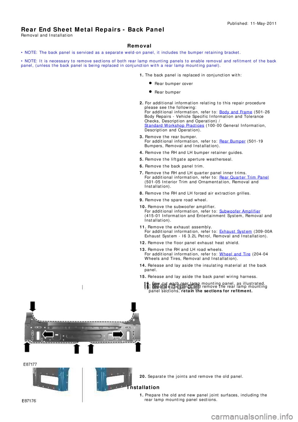
16. Saw cut each rear lamp mounting panel, as illustrated.17. Mill out the spot welds.18. Separate the joints and remove the rear lamp mounting
panel sections, retain the sections for refitment.19. Mill out the spot welds.
20. Separate the joints and remove the old panel.
Installation
1. Prepare the old and new panel joint surfaces, including the
rear l amp mount i ng panel s ect ions .
Page 2697 of 3229
Publ is hed: 11-May-2011
Uni-Body, Subframe and Mounting System - Front SubframeRemoval and Installation
S p e c ia l T o o l( s )
211-316
Se p a ra t o r, B a l l Jo i nt
502-012
Alignment Pins, Subframe
General Equipment
P o we rt ra i n Ja ck
Removal
1. WARNING: Make sure to support the vehicle with axle stands.
Raise and support the vehicle. 1.
Siphon the fluid from the power steering reservoir. 2.
Remove the front road wheels and tires.
Refer to: W heel and Tire
(204-04 W heels and Tires , Removal and Ins t all at i on). 3.
Remove the engine undershield.
Refer to: Engine Undershield
(501-02 Front End Body Panel s, Removal and
Installation). 4.
Di sconnect t he LH cat al ys t monit or sens or elect ri cal connect or. 5.
Page 2704 of 3229
18. WARNING: Make sure that a new steering column flexible coupling bolt is
installed.
Connect the steering column to the steering gear.
Torque: 25 Nm18.
Connect and s ecure t he cat alys t moni t or s ens or el ect ri cal connect ors . 19.
Install the 2 subframe mounting bolts and remove the jack. 20.
Install the engine undershield.
Refer to: Engine Undershield
(501-02 Front End Body Panel s, Removal and
Installation). 21.
Install the wheels and tires.
Refer to: W heel and Tire
(204-04 W heels and Tires , Removal and Ins t all at i on). 22.
Refill and bleed the power steering.
Refer to: Power Steering System Bleeding
(211-00 St eeri ng Sys t em - General
Informat ion, General Procedures). 23.
Using only four wheel alignment equipment approved by Land Rover, check and adjust
the wheel alignment. 24.
Page 2710 of 3229
6.
Repeat the above procedure on the opposite hand. 7.
8.
Repeat the above procedure on the opposite hand. 9.
10.
WARNING: Make sure to support the vehicle with axle
stands.
Raise and support the vehicle. 10.
Remove both rear wheels and tires.
Refer to: Wheel and Tire
(204-04 Wheels and Tires, Removal and
Installation). 11.
If installed, remove the rear suspension height sensor.
Refer to: Rear Suspension Height Sensor
(204-05 Vehi cl e Dynami c
Suspension, Removal and Installation). 12.
Remove the rear muffler.
Refer to: Exhaus t Sys t em
(309-00B Exhaus t Sys t em - TD4 2.2L
Diesel, Removal and Installation). 13.
Page 2716 of 3229

Torque: 5 NmSecure the lead in the clips.Repeat the above procedure for the other side.
LH side: Connect the ride height sensor electrical connector. 12.
Position and secure the rear shock absorbers.
Install both mass dampers.
Torque: 25 Nm
Repeat the above procedure for the other side.
13.
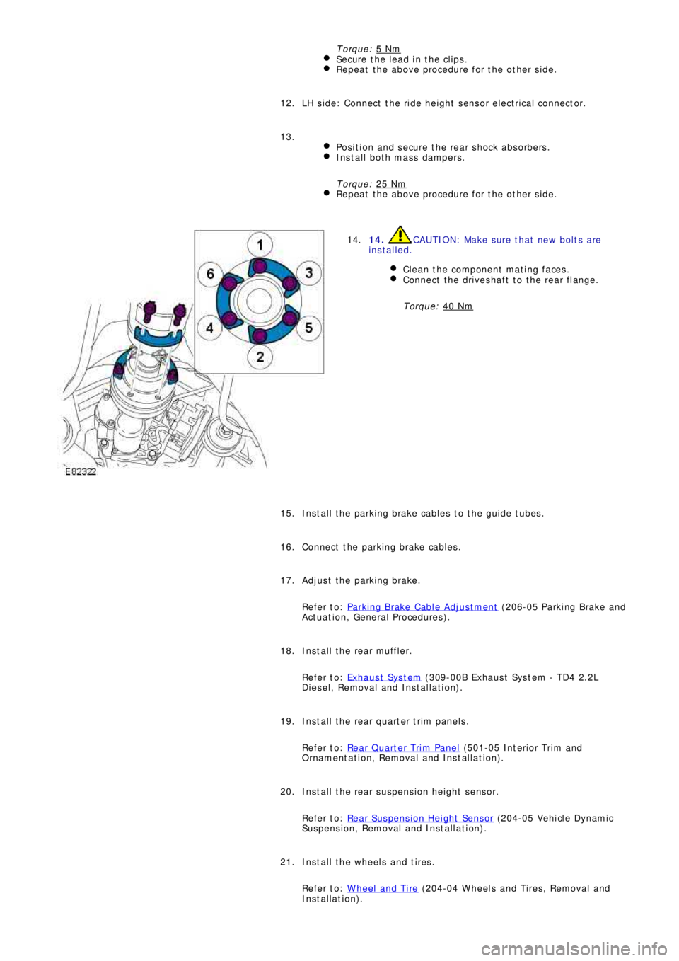
14. CAUTION: Make sure that new bolts are
installed.
Clean the component mating faces.
Connect the driveshaft to the rear flange.
Torque: 40 Nm
14.
Install the parking brake cables to the guide tubes. 15.
Connect the parking brake cables. 16.
Adjust the parking brake.
Refer to: Parking Brake Cable Adjustment
(206-05 Parki ng Brake and
Act uat i on, General Procedures ). 17.
Install the rear muffler.
Refer to: Exhaus t Sys t em
(309-00B Exhaus t Sys t em - TD4 2.2L
Diesel, Removal and Installation). 18.
Install the rear quarter trim panels.
Refer to: Rear Quarter Trim Panel
(501-05 Int eri or Tri m and
Ornament at i on, Removal and Ins t al lat i on). 19.
Install the rear suspension height sensor.
Refer to: Rear Suspension Height Sensor
(204-05 Vehi cl e Dynami c
Suspension, Removal and Installation). 20.
Install the wheels and tires.
Refer to: Wheel and Tire
(204-04 Wheels and Tires, Removal and
Installation). 21.
Page 2718 of 3229

Publ is hed: 11-May-2011
Uni-Body, Subframe and Mounting Syst em - Rear Subframe Front Bushing
Removal and Installation
S p e c ia l T o o l( s )
204-598
Hydraulic Cylinder 10t
204-598-01
Re mo ve r/I ns t a l l e r, Sub f ra me B us hi ng Gui d e
Removal
• NOTE: Removal steps in this procedure may contain installation details.
1.
WARNING: Make sure to support the vehicle with axle
stands.
Raise and support the vehicle.
1.
Remove both rear wheels and tires.
Refer to: Wheel and Tire
(204-04 Wheels and Tires, Removal and
Installation).
2.
Remove the rear subframe assembly for access.
Refer to: Rear Subframe
(502-00 Uni -Body, Subframe and Mount i ng
System, Removal and Installation).
3.
4.
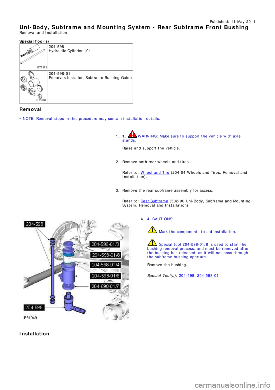
CAUTIONS:
Mark the components to aid installation.
Speci al t ool 204-598-01/8 i s us ed t o s t art t he
bushing removal process, and must be removed after
the bushing has released, as it will not pass through
the subframe bushing aperture.
Remove the bushing.
Special Tool(s): 204-598
, 204-598-01
4.
Installation
Page 2719 of 3229
1. CAUTIONS:
Make sure the correct special tool is used to
install the bushings to the correct depth.
Make sure that the installation marks are
aligned.
Install the bushing.
Special Tool(s): 204-598
, 204-598-01
1.
Install the rear subframe assembly.
Refer to: Rear Subframe
(502-00 Uni -Body, Subframe and Mount i ng
System, Removal and Installation).
2.
Install the wheels and tires.
Refer to: Wheel and Tire
(204-04 Wheels and Tires, Removal and
Installation).
3.