Page 3254 of 5267

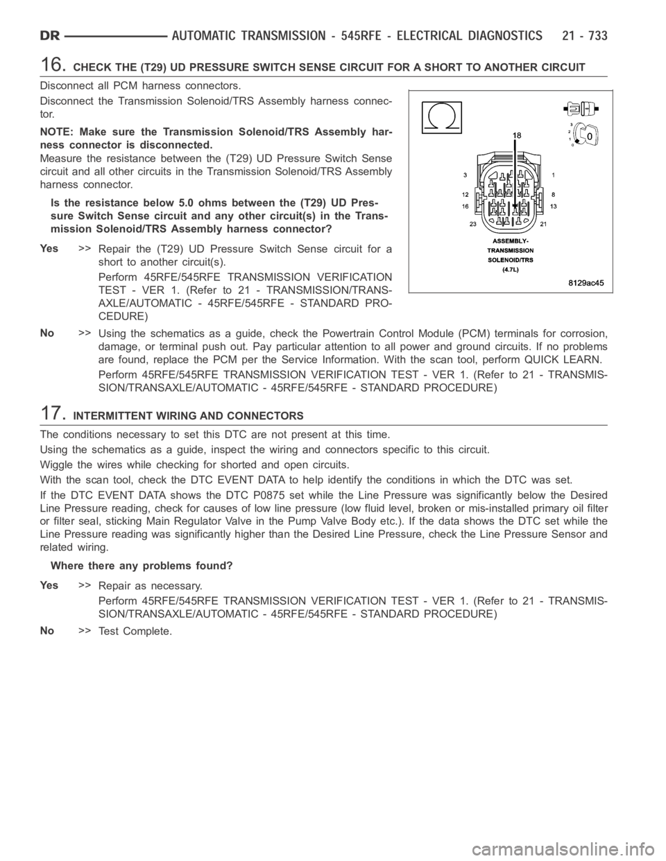
16.CHECK THE (T29) UD PRESSURE SWITCH SENSE CIRCUIT FOR A SHORT TO ANOTHER CIRCUIT
Disconnect all PCM harness connectors.
Disconnect the Transmission Solenoid/TRS Assembly harness connec-
tor.
NOTE: Make sure the Transmission Solenoid/TRS Assembly har-
ness connector is disconnected.
Measure the resistance between the (T29) UD Pressure Switch Sense
circuit and all other circuits in the Transmission Solenoid/TRS Assembly
harness connector.
Is the resistance below 5.0 ohms between the (T29) UD Pres-
sure Switch Sense circuit and any other circuit(s) in the Trans-
mission Solenoid/TRS Assembly harness connector?
Ye s>>
Repair the (T29) UD Pressure Switch Sense circuit for a
short to another circuit(s).
Perform 45RFE/545RFE TRANSMISSION VERIFICATION
TEST - VER 1. (Refer to 21 - TRANSMISSION/TRANS-
AXLE/AUTOMATIC - 45RFE/545RFE - STANDARD PRO-
CEDURE)
No>>
Using the schematics as a guide, check the Powertrain Control Module (PCM)terminals for corrosion,
damage, or terminal push out. Pay particular attention to all power and ground circuits. If no problems
are found, replace the PCM per the Service Information. With the scan tool,perform QUICK LEARN.
Perform 45RFE/545RFE TRANSMISSION VERIFICATION TEST - VER 1. (Refer to 21- TRANSMIS-
SION/TRANSAXLE/AUTOMATIC - 45RFE/545RFE - STANDARD PROCEDURE)
17.INTERMITTENT WIRING AND CONNECTORS
The conditions necessary to set this DTC are not present at this time.
Using the schematics as a guide, inspect the wiring and connectors specifictothiscircuit.
Wiggle the wires while checking for shorted and open circuits.
With the scan tool, check the DTC EVENT DATA to help identify the conditionsin which the DTC was set.
If the DTC EVENT DATA shows the DTC P0875 set while the Line Pressure was significantly below the Desired
Line Pressure reading, check for causes of low line pressure (low fluid level, broken or mis-installed primary oil filter
or filter seal, sticking Main Regulator Valve in the Pump Valve Body etc.).IfthedatashowstheDTCsetwhilethe
Line Pressure reading was significantly higher than the Desired Line Pressure, check the Line Pressure Sensor and
related wiring.
Where there any problems found?
Ye s>>
Repair as necessary.
Perform 45RFE/545RFE TRANSMISSION VERIFICATION TEST - VER 1. (Refer to 21- TRANSMIS-
SION/TRANSAXLE/AUTOMATIC - 45RFE/545RFE - STANDARD PROCEDURE)
No>>
Te s t C o m p l e t e .
Page 3255 of 5267
P0876-UD PRESSURE SWITCH RATIONALITY
For a complete wiring diagramRefer to Section 8W
Page 3258 of 5267

7.CHECK THE UD PRESSURE SWITCH STATUS
Refer to the DTC EVENT DATA recorded earlier.
Did the DTC P0876 set with the UD Pressure Switch closed?
Ye s>>
Go To 10
No>>
Go To 8
8.CHECK THE LINE PRESSURE
In the DTC EVENT DATA recorded earlier,compare the Line Pressure and the Desired Line Pressure.
Is the Line Pressure less than 40 psi, and significantly below the Desired Line Pressure?
Ye s>>
Repair as necessary to correct low line pressure. Check fluid level and adjustasnecessary.Iffluidlevel
is OK, check the Primary Oil Filter seal for a split, crack, or improperly installed. If the filter and seal are
OK, check the Main Regulator Valve in the Oil Pump. Refer to the Service Information for the above
procedures.
Perform 45RFE/545RFE TRANSMISSION VERIFICATION TEST - VER 1. (Refer to 21- TRANSMIS-
SION/TRANSAXLE/AUTOMATIC - 45RFE/545RFE - STANDARD PROCEDURE)
No>>
Go To 9
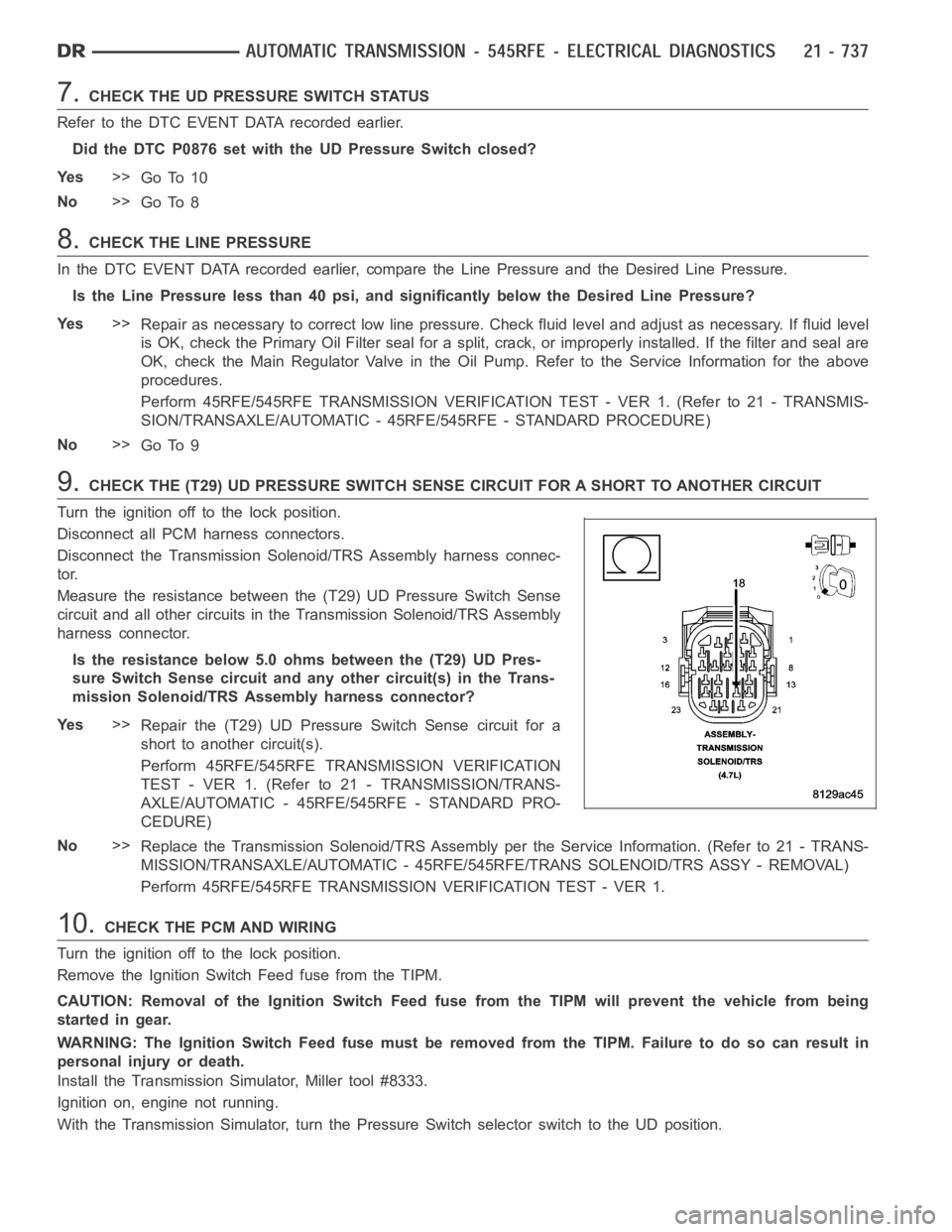
9.CHECK THE (T29) UD PRESSURE SWITCH SENSE CIRCUIT FOR A SHORT TO ANOTHER CIRCUIT
Turn the ignition off to the lock position.
Disconnect all PCM harness connectors.
Disconnect the Transmission Solenoid/TRS Assembly harness connec-
tor.
Measure the resistance between the (T29) UD Pressure Switch Sense
circuit and all other circuits in the Transmission Solenoid/TRS Assembly
harness connector.
Is the resistance below 5.0 ohms between the (T29) UD Pres-
sure Switch Sense circuit and any other circuit(s) in the Trans-
mission Solenoid/TRS Assembly harness connector?
Ye s>>
Repair the (T29) UD Pressure Switch Sense circuit for a
short to another circuit(s).
Perform 45RFE/545RFE TRANSMISSION VERIFICATION
TEST - VER 1. (Refer to 21 - TRANSMISSION/TRANS-
AXLE/AUTOMATIC - 45RFE/545RFE - STANDARD PRO-
CEDURE)
No>>
Replace the Transmission Solenoid/TRS Assembly per the Service Information. (Refer to 21 - TRANS-
MISSION/TRANSAXLE/AUTOMATIC - 45RFE/545RFE/TRANS SOLENOID/TRS ASSY -REMOVAL)
Perform 45RFE/545RFE TRANSMISSION VERIFICATION TEST - VER 1.
10.CHECK THE PCM AND WIRING
Turn the ignition off to the lock position.
Remove the Ignition Switch Feed fuse from the TIPM.
CAUTION: Removal of the Ignition Switch Feed fuse from the TIPM will prevent the vehicle from being
startedingear.
WARNING: The Ignition Switch Feed fuse must be removed from the TIPM. Failure to do so can result in
personal injury or death.
Install the Transmission Simulator, Miller tool #8333.
Ignition on, engine not running.
With the Transmission Simulator, turn the Pressure Switch selector switch to the UD position.
Page 3260 of 5267

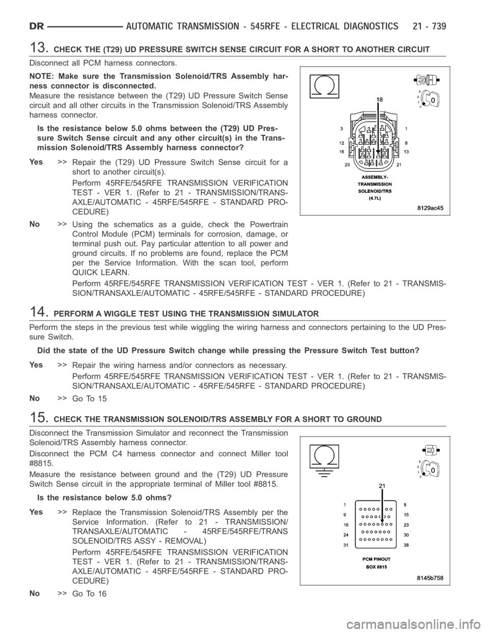
13.CHECK THE (T29) UD PRESSURE SWITCH SENSE CIRCUIT FOR A SHORT TO ANOTHER CIRCUIT
Disconnect all PCM harness connectors.
NOTE: Make sure the Transmission Solenoid/TRS Assembly har-
ness connector is disconnected.
Measure the resistance between the (T29) UD Pressure Switch Sense
circuit and all other circuits in the Transmission Solenoid/TRS Assembly
harness connector.
Is the resistance below 5.0 ohms between the (T29) UD Pres-
sure Switch Sense circuit and any other circuit(s) in the Trans-
mission Solenoid/TRS Assembly harness connector?
Ye s>>
Repair the (T29) UD Pressure Switch Sense circuit for a
short to another circuit(s).
Perform 45RFE/545RFE TRANSMISSION VERIFICATION
TEST - VER 1. (Refer to 21 - TRANSMISSION/TRANS-
AXLE/AUTOMATIC - 45RFE/545RFE - STANDARD PRO-
CEDURE)
No>>
Using the schematics as a guide, check the Powertrain
Control Module (PCM) terminals for corrosion, damage, or
terminal push out. Pay particular attention to all power and
ground circuits. If no problems are found, replace the PCM
per the Service Information.With the scan tool, perform
QUICK LEARN.
Perform 45RFE/545RFE TRANSMISSION VERIFICATION TEST - VER 1. (Refer to 21- TRANSMIS-
SION/TRANSAXLE/AUTOMATIC - 45RFE/545RFE - STANDARD PROCEDURE)
14.PERFORM A WIGGLE TEST USING THE TRANSMISSION SIMULATOR
Perform the steps in the previous test while wiggling the wiring harness and connectors pertaining to the UD Pres-
sure Switch.
Did the state of the UD Pressure Switch change while pressing the Pressure Switch Test button?
Ye s>>
Repair the wiring harness and/or connectors as necessary.
Perform 45RFE/545RFE TRANSMISSION VERIFICATION TEST - VER 1. (Refer to 21- TRANSMIS-
SION/TRANSAXLE/AUTOMATIC - 45RFE/545RFE - STANDARD PROCEDURE)
No>>
Go To 15
15.CHECK THE TRANSMISSION SOLENOID/TRS ASSEMBLY FOR A SHORT TO GROUND
Disconnect the Transmission Simulator and reconnect the Transmission
Solenoid/TRS Assembly harness connector.
Disconnect the PCM C4 harness connector and connect Miller tool
#8815.
Measure the resistance between ground and the (T29) UD Pressure
Switch Sense circuit in the appropriate terminal of Miller tool #8815.
Is the resistance below 5.0 ohms?
Ye s>>
Replace the Transmission Solenoid/TRS Assembly per the
Service Information. (Refer to 21 - TRANSMISSION/
TRANSAXLE/AUTOMATIC - 45RFE/545RFE/TRANS
SOLENOID/TRS ASSY - REMOVAL)
Perform 45RFE/545RFE TRANSMISSION VERIFICATION
TEST - VER 1. (Refer to 21 - TRANSMISSION/TRANS-
AXLE/AUTOMATIC - 45RFE/545RFE - STANDARD PRO-
CEDURE)
No>>
Go To 16
Page 3261 of 5267

16.CHECK IF THE DTC RESETS
Reconnect all previously disconnected connectors.
With the scan tool, erase all transmission DTCs.
Test drive the vehicle. Using the DTC EVENT DATA recorded earlier, try to duplicate the conditions in which the
DTC originally set.
Does the DTC P0876 reset?
Ye s>>
Go To 17
No>>
Go To 18
17.CHECK FOR A CUT NO. 2 CHECK BALL
Remove the Valve Body per the Service Information.
Check the No. 2 check ball for cuts or damage.
Is the No. 2 check ball cut or damaged?
Ye s>>
Replace the No. 2 check ball. Check for excessive clutch debris in the oil pan. If excessive debris is
present, check the UD Clutch and repair as necessary.
Perform 45RFE/545RFE TRANSMISSION VERIFICATION TEST - VER 1. (Refer to 21- TRANSMIS-
SION/TRANSAXLE/AUTOMATIC - 45RFE/545RFE - STANDARD PROCEDURE)
No>>
Replace the Transmission Solenoid/TRS Assembly per the Service Information. Check for excessive
clutch debris in the oil pan. If excessive debris is present, check the UD Clutch and repair as necessary.
(Refer to 21 - TRANSMISSION/TRANSAXLE/AUTOMATIC - 45RFE/545RFE/TRANS SOLENOID/TRS
ASSY - REMOVAL)
Perform 45RFE/545RFE TRANSMISSION VERIFICATION TEST - VER 1. (Refer to 21- TRANSMIS-
SION/TRANSAXLE/AUTOMATIC - 45RFE/545RFE - STANDARD PROCEDURE)
18.CHECK FOR INTERMITTENT WIRING AND CONNECTORS
The conditions necessary to set this DTC are not present at this time.
Using the schematics as a guide, inspect the wiring and connectors specifictothiscircuit.
Wiggle the wires while checking for shorted and open circuits.
With the scan tool, check the DTC EVENT DATA to help identify the conditionsin which the DTC was set.
Were there any problems found?
Ye s>>
Repair as necessary.
Perform 45RFE/545RFE TRANSMISSION VERIFICATION TEST - VER 1. (Refer to 21- TRANSMIS-
SION/TRANSAXLE/AUTOMATIC - 45RFE/545RFE - STANDARD PROCEDURE)
No>>
Te s t C o m p l e t e .
Page 3262 of 5267
P0882-TCM POWER INPUT LOW
For a complete wiring diagramRefer to Section 8W
Page 3265 of 5267
5.CHECK THE WIRING AND CONNECTORS
The conditions necessary to set this DTC are not present at this time.
Using the schematics as a guide, inspect the wiring and connectors specifictothiscircuit.
Wiggle the wires while checking for shorted and open circuits.
With the scan tool, check the DTC EVENT DATA to help identify the conditionsin which the DTC was set.
Where there any problems found?
Ye s>>
Repair as necessary.
Perform 45RFE/545RFE TRANSMISSION VERIFICATION TEST - VER 1. (Refer to 21- TRANSMIS-
SION/TRANSAXLE/AUTOMATIC - 45RFE/545RFE - STANDARD PROCEDURE)
No>>
Te s t C o m p l e t e .
Page 3266 of 5267
P0883-TCM POWER INPUT HIGH
For a complete wiring diagramRefer to Section 8W.