2006 DODGE RAM SRT-10 lock
[x] Cancel search: lockPage 3348 of 5267
3.4C CLUTCH CIRCUIT LEAKS IN THE VALVE BODY
Turn the ignition off to the lock position.
Remove the transmission oil pan per the Service Information.
Remove the valve body per the Service Information.
Check condition of the 4C accumulator springs.
Look for possible leak paths into the 4C clutch hydraulics circuit within the valve body.
Were any problems found?
Ye s>>
Repair as necessary.
Perform 45RFE/545RFE TRANSMISSION VERIFICATION TEST - VER 1. (Refer to 21- TRANSMIS-
SION/TRANSAXLE/AUTOMATIC - 45RFE/545RFE - STANDARD PROCEDURE)
No>>
Go To 4
4.AIR CHECK 4C CLUTCH CIRCUIT
Perform an air check on the 4C Clutch circuit per the Service Information.
Listen for proper 4C Clutch piston movement.
Were any problems found?
Ye s>>
Repair Internal transmission as necessary. Pay attention to the mechanical components related to the
4th clutch. A broken or weak return spring or a dislocated snap ring could cause this problem.
Perform 45RFE/545RFE TRANSMISSION VERIFICATION TEST - VER 1. (Refer to 21- TRANSMIS-
SION/TRANSAXLE/AUTOMATIC - 45RFE/545RFE - STANDARD PROCEDURE)
No>>
Replace the Transmission Solenoid/TRS Assembly per the service information. With the scan tool, per-
form Quick Learn.
Perform 45RFE/545RFE TRANSMISSION VERIFICATION TEST - VER 1. (Refer to 21- TRANSMIS-
SION/TRANSAXLE/AUTOMATIC - 45RFE/545RFE - STANDARD PROCEDURE)
5.VERIFY PCM OPERATION
Perform eight learnable starts. A learnable start is defined as follows: Start engine. From a standstill, accelerate
lightly to 50 MPH, then brake lightly to a stop. Turn off engine.
With the scan tool, record Transmission CL VOL INDEX (CVI) for all clutches.
With the scan tool, perform a BATTERY DISCONNECT.
With the scan tool, read the CVI’s and compare them to the reading recorded before the BATTERY DISCONNECT.
Are any of the CVI’s less than 5 or are they different than before the batterydisconnect?
Ye s>>
Using the schematics as a guide, check the Powertrain Control Module (PCM)terminals for corrosion,
damage, or terminal push out. Pay particular attention to all power and ground circuits. If no problems
are found, replace the PCM per the Service Information. With the scan tool,perform QUICK LEARN.
Perform 45RFE/545RFE TRANSMISSION VERIFICATION TEST - VER 1. (Refer to 21- TRANSMIS-
SION/TRANSAXLE/AUTOMATIC - 45RFE/545RFE - STANDARD PROCEDURE)
No>>
Te s t C o m p l e t e .
Page 3350 of 5267
When Monitored:
Initially at power-up, then every 10 seconds thereafter. The solenoid circuits will also be tested immediately
after a gear ratio or pressure switch error is detected.
Set Condition:
After three consecutive solenoid continuity test failures, or one failure if test is run in response to a gear ratio
or pressure switch error.Note: This DTC is strictly an electrical fault and does not apply to any internal
transmission failures.
Possible Causes
RELATED TCM POWER INPUT DTCS PRESENT
(T118) MS SOLENOID CONTROL CIRCUIT SHORT TO OTHER CIRCUITS
(T118) MS SOLENOID CONTROL CIRCUIT OPEN
(T118) MS SOLENOID CONTROL CIRCUIT SHORT TO GROUND
TRANSMISSION SOLENOID/TRS ASSEMBLY
POWERTRAIN CONTROL MODULE
Always perform the 45RFE/545RFE Pre-Diagnostic Troubleshooting Procedure before proceeding. (Refer to
21 - TRANSMISSION/TRANSAXLE/AUTOMATIC - 45RFE/545RFE - STANDARD PROCEDURE)
Theory of Operation
The Transmission Control System uses six electronically controlled solenoids that allow hydraulic fluid to be applied
to various friction elements (clutches), which enables the gear requested. The continuity of each solenoid circuit is
periodically tested. Each inactive solenoid is turned on for a few milliseconds, then off. Each active solenoid is
turned off for a few milliseconds, then on. This pulsing of voltage to the solenoid causes an inductive spike which
can be sensed by the Transmission Control System. If an inductive spike is not sensed by the Transmission Control
System during the continuity check, it is tested again. If the test fails three consecutive times, the appropriate Diag-
nostic Trouble Code (DTC) is set. If the solenoid test is run in response to agear ratio or pressure switch error, one
failure will result in setting the appropriate DTC.Note: This DTC is strictly an electrical fault and does not apply
to any internal transmission failures.
Diagnostic Test
1.RELATED TCM POWER INPUT DTCS PRESENT
With the scan tool, check for other transmission DTCs.
Are there any TCM Power Input DTCs present?
Ye s>>
Refer to the Transmission category and perform the appropriate symptom.
No>>
Go To 2
2.TRANSMISSION SOLENOID/TRS ASSEMBLY
Turn the ignition off to the lock position.
Remove the Ignition Switch Feed fuse from the TIPM.
CAUTION: Removal of the Ignition Switch Feed fuse from the TIPM will prevent the vehicle from being
startedingear.
WARNING: The Ignition Switch Feed fuse must be removed from the TIPM. Failure to do so can result in
personal injury or death.
Install Transmission Simulator, Miller tool #8333.
Ignition on, engine not running.
With the scan tool, actuate the MS Solenoid.
Page 3351 of 5267
Monitor the MS Solenoid LED on the Transmission Simulator.
Did the MS Solenoid LED on the Transmission Simulator blink on and off?
Ye s>>
Replace the Transmission Solenoid/TRS Assembly per the Service Information.
Perform 45RFE/545RFE TRANSMISSION VERIFICATION TEST - VER 1. (Refer to 21- TRANSMIS-
SION/TRANSAXLE/AUTOMATIC - 45RFE/545RFE - STANDARD PROCEDURE)
No>>
Go To 3
3.TRANSMISSION SOLENOID/TRS ASSEMBLY
With the scan tool, continue to actuate the MS Solenoid for the period of 2 minutes with the Transmission Simulator
still connected.
After 2 minutes of actuation, with the scan tool, stop the actuation and check for transmission DTCs.
Did the DTC P2706 reset during the actuation test?
Ye s>>
Go To 4
No>> Perform 45RFE/545RFE TRANSMISSION VERIFICATION TEST - VER 1. (Refer to21 - TRANSMIS-
SION/TRANSAXLE/AUTOMATIC - 45RFE/545RFE - STANDARD PROCEDURE)
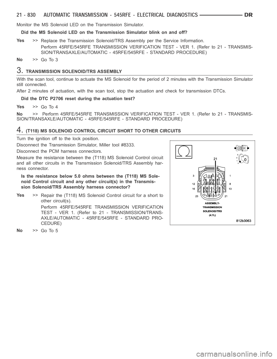
4.(T118) MS SOLENOID CONTROL CIRCUIT SHORT TO OTHER CIRCUITS
Turn the ignition off to the lock position.
Disconnect the Transmission Simulator, Miller tool #8333.
Disconnect the PCM harness connectors.
Measure the resistance between the (T118) MS Solenoid Control circuit
and all other circuits in the Transmission Solenoid/TRS Assembly har-
ness connector.
Is the resistance below 5.0 ohms between the (T118) MS Sole-
noid Control circuit and any other circuit(s) in the Transmis-
sion Solenoid/TRS Assembly harness connector?
Ye s>>
Repair the (T118) MS Solenoid Control circuit for a short to
other circuit(s).
Perform 45RFE/545RFE TRANSMISSION VERIFICATION
TEST - VER 1. (Refer to 21 - TRANSMISSION/TRANS-
AXLE/AUTOMATIC - 45RFE/545RFE - STANDARD PRO-
CEDURE)
No>>
Go To 5
Page 3363 of 5267
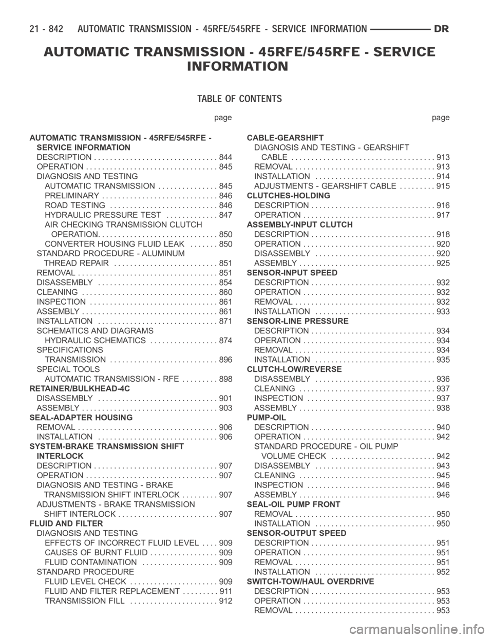
page page
AUTOMATIC TRANSMISSION - 45RFE/545RFE -
SERVICE INFORMATION
DESCRIPTION ............................... 844
OPERATION ................................. 845
DIAGNOSIS AND TESTING
AUTOMATIC TRANSMISSION ............... 845
PRELIMINARY ............................. 846
ROAD TESTING ........................... 846
HYDRAULIC PRESSURE TEST............. 847
AIR CHECKING TRANSMISSION CLUTCH
OPERATION............................... 850
CONVERTER HOUSING FLUID LEAK ....... 850
STANDARD PROCEDURE - ALUMINUM
THREAD REPAIR .......................... 851
REMOVAL ................................... 851
DISASSEMBLY .............................. 854
CLEANING .................................. 860
INSPECTION ................................ 861
ASSEMBLY .................................. 861
INSTALLATION .............................. 871
SCHEMATICS AND DIAGRAMS
HYDRAULIC SCHEMATICS ................. 874
SPECIFICATIONS
TRANSMISSION ........................... 896
SPECIAL TOOLS
AUTOMATIC TRANSMISSION - RFE ......... 898
RETAINER/BULKHEAD-4C
DISASSEMBLY .............................. 901
ASSEMBLY .................................. 903
SEAL-ADAPTER HOUSING
REMOVAL ................................... 906
INSTALLATION .............................. 906
SYSTEM-BRAKE TRANSMISSION SHIFT
INTERLOCK
DESCRIPTION ............................... 907
OPERATION ................................. 907
DIAGNOSIS AND TESTING - BRAKE
TRANSMISSION SHIFT INTERLOCK ......... 907
ADJUSTMENTS - BRAKE TRANSMISSION
SHIFT INTERLOCK ......................... 907
FLUID AND FILTER
DIAGNOSIS AND TESTING
EFFECTS OF INCORRECT FLUID LEVEL.... 909
CAUSES OF BURNT FLUID ................. 909
FLUID CONTAMINATION ................... 909
STANDARD PROCEDURE
FLUID LEVEL CHECK . ..................... 909
FLUID AND FILTER REPLACEMENT ......... 911
TRANSMISSION FILL ...................... 912CABLE-GEARSHIFT
DIAGNOSIS AND TESTING - GEARSHIFT
CABLE .................................... 913
REMOVAL ................................... 913
INSTALLATION .............................. 914
ADJUSTMENTS - GEARSHIFT CABLE ......... 915
CLUTCHES-HOLDING
DESCRIPTION ............................... 916
OPERATION ................................. 917
ASSEMBLY-INPUT CLUTCH
DESCRIPTION ............................... 918
OPERATION ................................. 920
DISASSEMBLY .............................. 920
ASSEMBLY .................................. 925
SENSOR-INPUT SPEED
DESCRIPTION ............................... 932
OPERATION ................................. 932
REMOVAL ................................... 932
INSTALLATION .............................. 933
SENSOR-LINE PRESSURE
DESCRIPTION ............................... 934
OPERATION ................................. 934
REMOVAL ................................... 934
INSTALLATION .............................. 935
CLUTCH-LOW/REVERSE
DISASSEMBLY .............................. 936
CLEANING .................................. 937
INSPECTION . . .............................. 937
ASSEMBLY .................................. 938
PUMP-OIL
DESCRIPTION ............................... 940
OPERATION ................................. 942
STANDARD PROCEDURE - OIL PUMP
VOLUME CHECK .......................... 942
DISASSEMBLY .............................. 943
CLEANING .................................. 945
INSPECTION . . .............................. 946
ASSEMBLY .................................. 946
SEAL-OIL PUMP FRONT
REMOVAL ................................... 950
INSTALLATION .............................. 950
SENSOR-OUTPUT SPEED
DESCRIPTION ............................... 951
OPERATION ................................. 951
REMOVAL ................................... 951
INSTALLATION .............................. 952
SWITCH-TOW/HAUL OVERDRIVE
DESCRIPTION ............................... 953
OPERATION ................................. 953
REMOVAL ................................... 953
Page 3371 of 5267
vehicles. Torque converter lock-up pressure is 120 psi for 3.7L/4.7L equipped vehicles and 125 psi for 5.7L
equipped vehicles.
UPSHIFT PRESSURES
ENGINE 1-2 2-3 2prime-3 3-4 2prime-4 2-5 3-5 4-5
5.7L150 125 125 135 135 135 135 135
3.7L/4.7L120 120 120 120 120 120 120 130
DOWNSHIFT PRESSURES
ENGINE 5-4 5-3 5-2 4-3 4-
2prime3-2 3-
2prime2prime-1 2-1 3-1
5.7L135 135 135 135 135 135 135 135 135 135
3.7L/
4.7L120 120 120 120 120 120 120 120 120 120
IN-GEAR PRESSURES
ENGINE122prime345NEUTRALREVERSE
5.7L160 135 135 135 135 135 120 250
3.7L/4.7L135 120 120 120 120 120 120 220
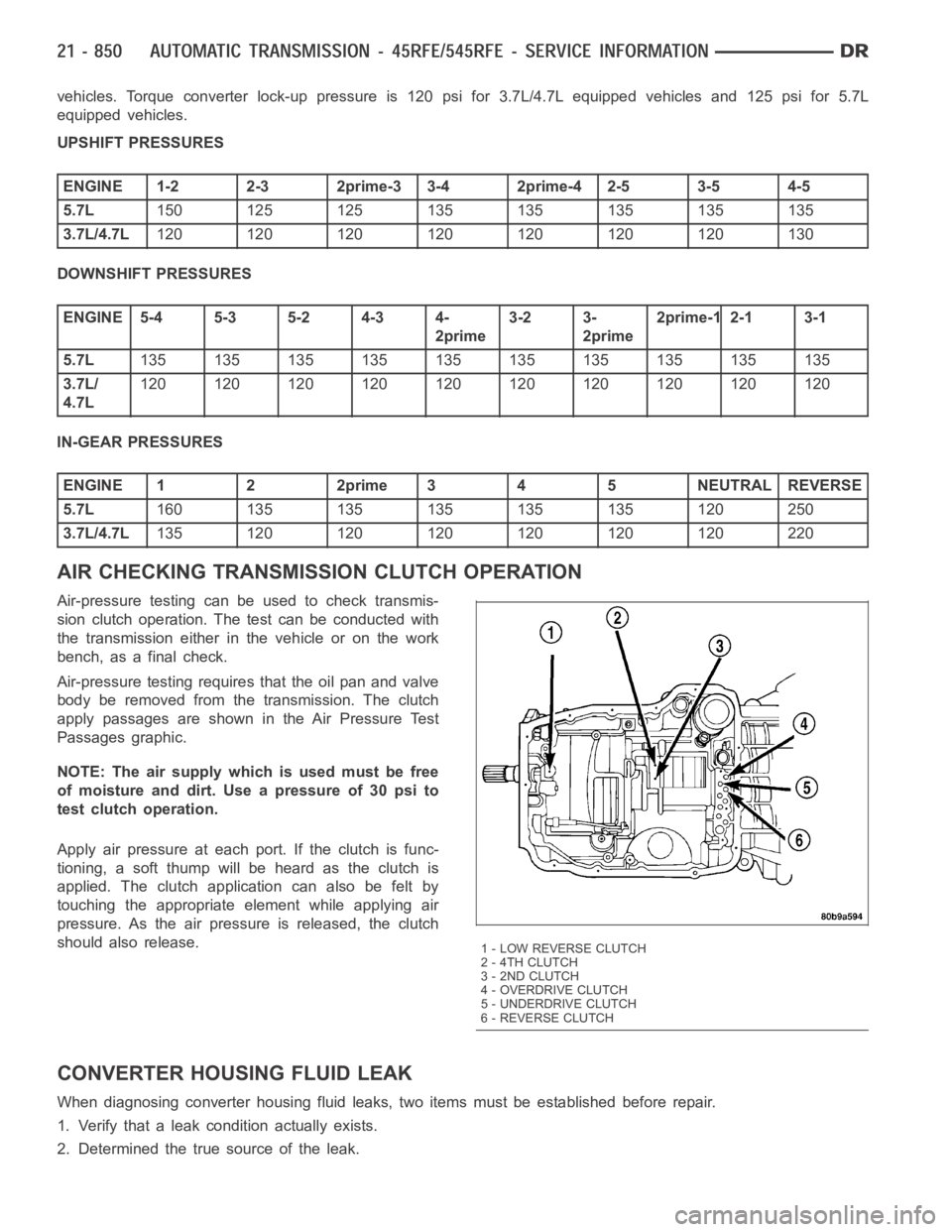
AIR CHECKING TRANSMISSION CLUTCH OPERATION
Air-pressure testing can be used to check transmis-
sion clutch operation. The test can be conducted with
the transmission either in the vehicle or on the work
bench, as a final check.
Air-pressure testing requires that the oil pan and valve
body be removed from the transmission. The clutch
apply passages are shown in the Air Pressure Test
Passages graphic.
NOTE: The air supply which is used must be free
ofmoistureanddirt.Useapressureof30psito
test clutch operation.
Apply air pressure at each port. If the clutch is func-
tioning, a soft thump will be heard as the clutch is
applied. The clutch application can also be felt by
touching the appropriate element while applying air
pressure. As the air pressure is released, the clutch
should also release.
CONVERTER HOUSING FLUID LEAK
When diagnosing converter housing fluid leaks, two items must be established before repair.
1. Verify that a leak condition actually exists.
2. Determined the true source of the leak.
1 - LOW REVERSE CLUTCH
2 - 4TH CLUTCH
3 - 2ND CLUTCH
4-OVERDRIVECLUTCH
5 - UNDERDRIVE CLUTCH
6 - REVERSE CLUTCH
Page 3373 of 5267
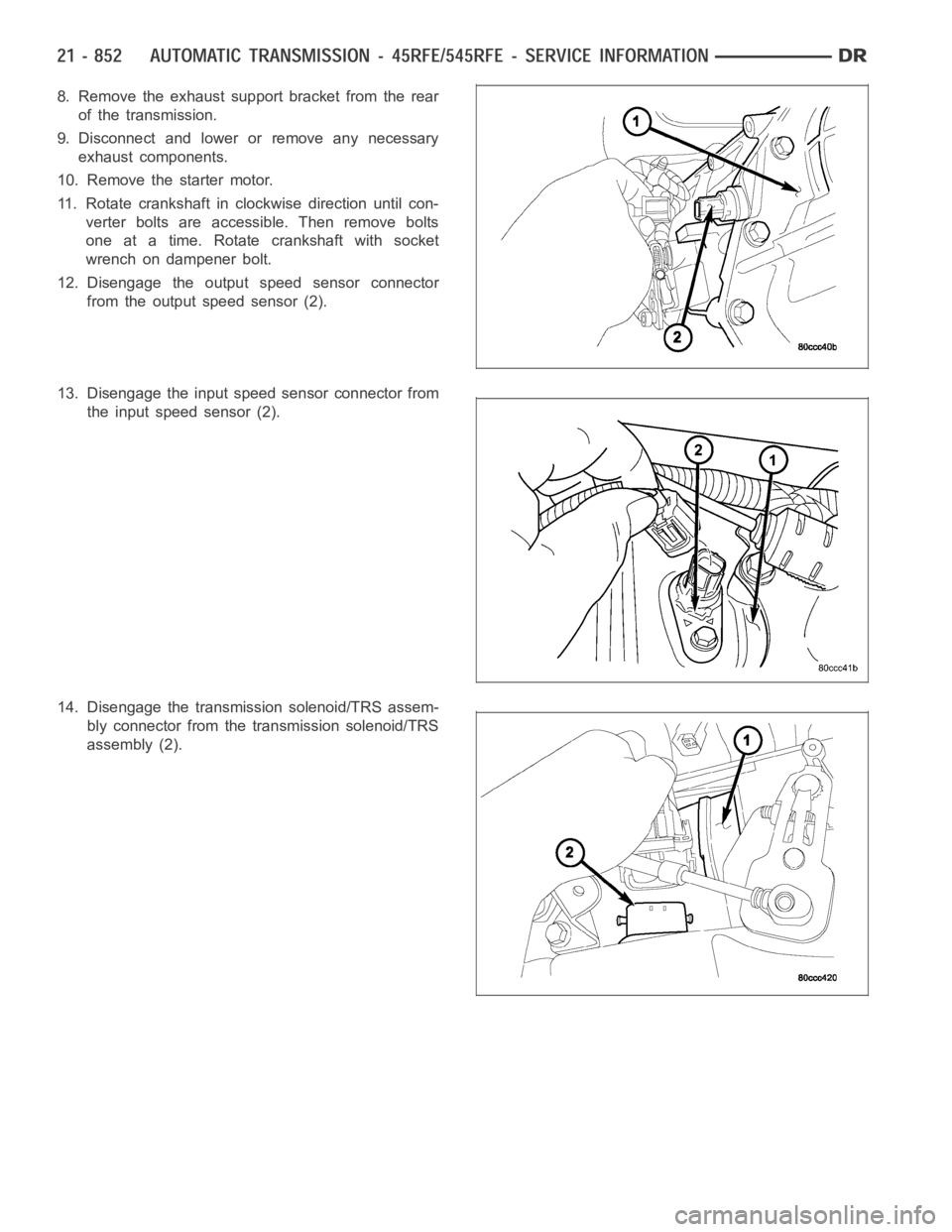
8. Remove the exhaust support bracket from the rear
of the transmission.
9. Disconnect and lower or remove any necessary
exhaust components.
10. Remove the starter motor.
11. Rotate crankshaft in clockwise direction until con-
verter bolts are accessible. Then remove bolts
one at a time. Rotate crankshaft with socket
wrench on dampener bolt.
12. Disengage the output speed sensor connector
from the output speed sensor (2).
13. Disengage the input speed sensor connector from
the input speed sensor (2).
14. Disengage the transmission solenoid/TRS assem-
bly connector from the transmission solenoid/TRS
assembly (2).
Page 3374 of 5267
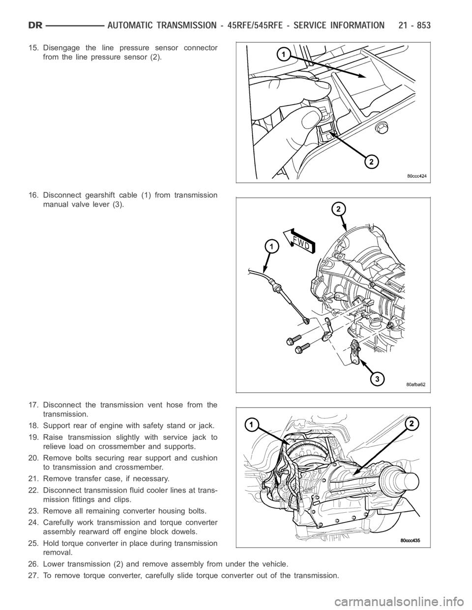
15. Disengage the line pressure sensor connector
from the line pressure sensor (2).
16. Disconnect gearshift cable (1) from transmission
manual valve lever (3).
17. Disconnect the transmission vent hose from the
transmission.
18. Support rear of engine with safety stand or jack.
19. Raise transmission slightly with service jack to
relieve load on crossmember and supports.
20. Remove bolts securing rear support and cushion
to transmission and crossmember.
21. Remove transfer case, if necessary.
22. Disconnect transmission fluid cooler lines at trans-
mission fittings and clips.
23. Remove all remaining converter housing bolts.
24. Carefully work transmission and torque converter
assembly rearward off engine block dowels.
25. Hold torque converter in place during transmission
removal.
26. Lower transmission (2) and remove assembly from under the vehicle.
27. To remove torque converter, carefully slide torque converter out of the transmission.
Page 3382 of 5267
NOTE: Do not use shop towels or rags to dry the case (or any other transmission component) unless they
aremadefromlint-freematerials.Lintwillsticktocasesurfacesandtransmission components and circu-
late throughout the transmission after assembly. A sufficient quantity of lint can block fluid passages and
interfere with valve body operation.
INSPECTION
Inspect the case for cracks, porous spots, worn bores, or damaged threads.Damaged threads can be repaired with
Helicoil
thread inserts. However, the case will have to be replaced if it exhibits any type of damage or wear.
ASSEMBLY
NOTE: Clean and inspect all components. Replace any components which showevidence of excessive wear
or scoring.
1. Install the cooler filter bypass valve. Torque the
bypass valve to specification. The valve uses a
tapered pipe thread and excessive torque can
damage the transmission case. Tighten the cooler
filter bypass valve to 4.5 Nꞏm (40 in.lbs.).
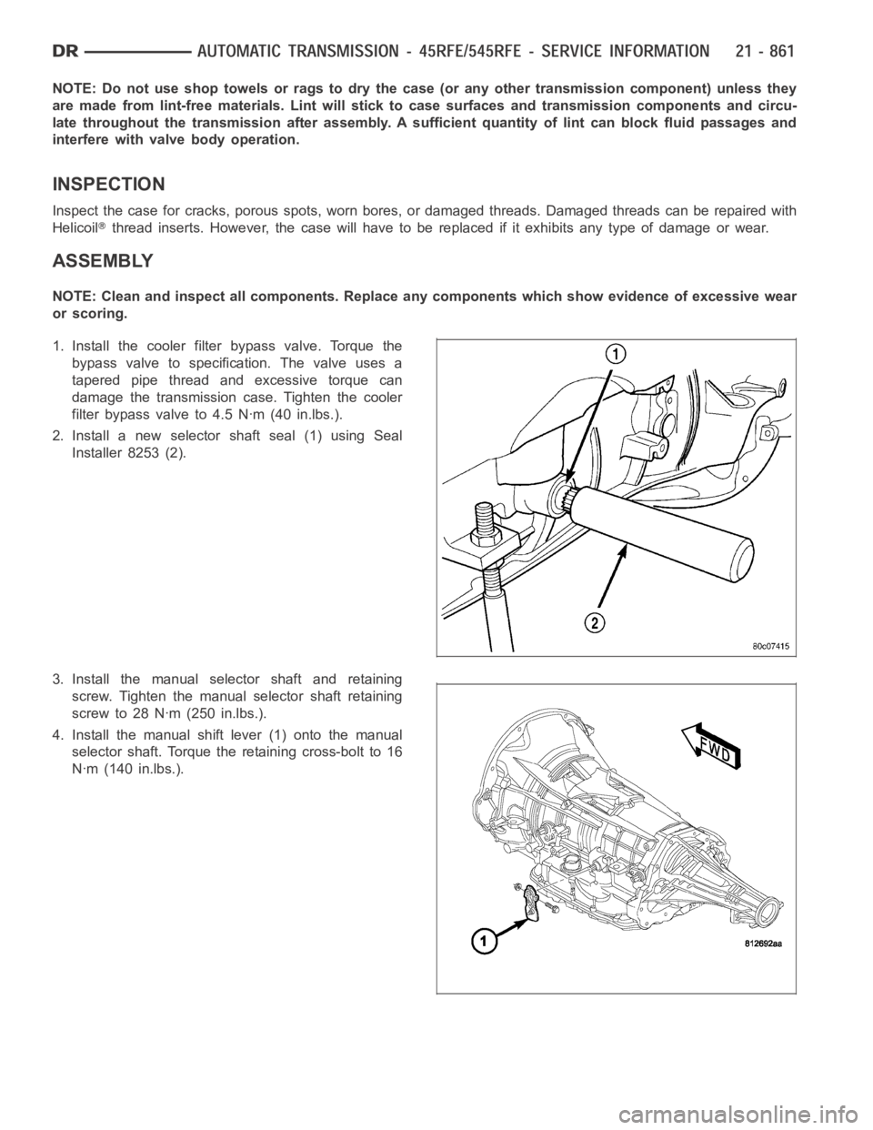
2. Install a new selector shaft seal (1) using Seal
Installer 8253 (2).
3. Install the manual selector shaft and retaining
screw. Tighten the manual selector shaft retaining
screw to 28 Nꞏm (250 in.lbs.).
4. Install the manual shift lever (1) onto the manual
selector shaft. Torque the retaining cross-bolt to 16
Nꞏm (140 in.lbs.).