2006 DODGE RAM SRT-10 lock
[x] Cancel search: lockPage 3485 of 5267
TORQUE CONVERTER CLUTCH (TCC)
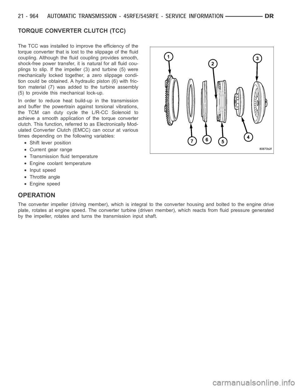
The TCC was installed to improve the efficiency of the
torque converter that is lost to the slippage of the fluid
coupling. Although the fluid coupling provides smooth,
shock-free power transfer, it is natural for all fluid cou-
plings to slip. If the impeller (3) and turbine (5) were
mechanically locked together, a zero slippage condi-
tion could be obtained. A hydraulic piston (6) with fric-
tion material (7) was added to the turbine assembly
(5) to provide this mechanical lock-up.
In order to reduce heat build-up in the transmission
and buffer the powertrain against torsional vibrations,
the TCM can duty cycle the L/R-CC Solenoid to
achieve a smooth application of the torque converter
clutch. This function, referred to as Electronically Mod-
ulated Converter Clutch (EMCC) can occur at various
times depending on the following variables:
Shift lever position
Current gear range
Transmission fluid temperature
Engine coolant temperature
Input speed
Throttle angle
Engine speed
OPERATION
The converter impeller (driving member), which is integral to the converter housing and bolted to the engine drive
plate, rotates at engine speed. The converter turbine (driven member), which reacts from fluid pressure generated
by the impeller, rotates and turns the transmission input shaft.
Page 3486 of 5267
TURBINE
As the fluid that was put into motion bythe impeller blades strikes the blades of the turbine, some of the energy and
rotational force is transferred into the turbine and the input shaft. Thiscauses both of them (turbine and input shaft)
to rotate in a clockwise direction following the impeller. As the fluid is leaving the trailing edges of the turbine’s
blades it continues in a “hindering” direction back toward the impeller. If the fluid is not redirected before it strikes
the impeller, it will strike the impeller in such a direction that it would tend to slow it down.
STATOR
Torque multiplication is achieved by locking the stator’s over-running clutch to its shaft. Under stall conditions (the
turbine is stationary), the oil leaving the turbine blades strikes the face of the stator blades and tries to rotate them
in a counterclockwise direction. When this happens the over-running clutch of the stator locks and holds the stator
from rotating. With the stator locked, the oil strikes the stator blades and is redirected into a “helping” direction
before it enters the impeller. This circulation of oil from impeller to turbine, turbine to stator, and stator to impeller,
can produce a maximum torque multiplicationofabout2.4:1.Astheturbinebegins to match the speed of the impel-
ler, the fluid that was hitting the stator in such as way as to cause it to lock-up is no longer doing so. In this con-
dition of operation, the stator begins to free wheel and the converter actsas a fluid coupling.
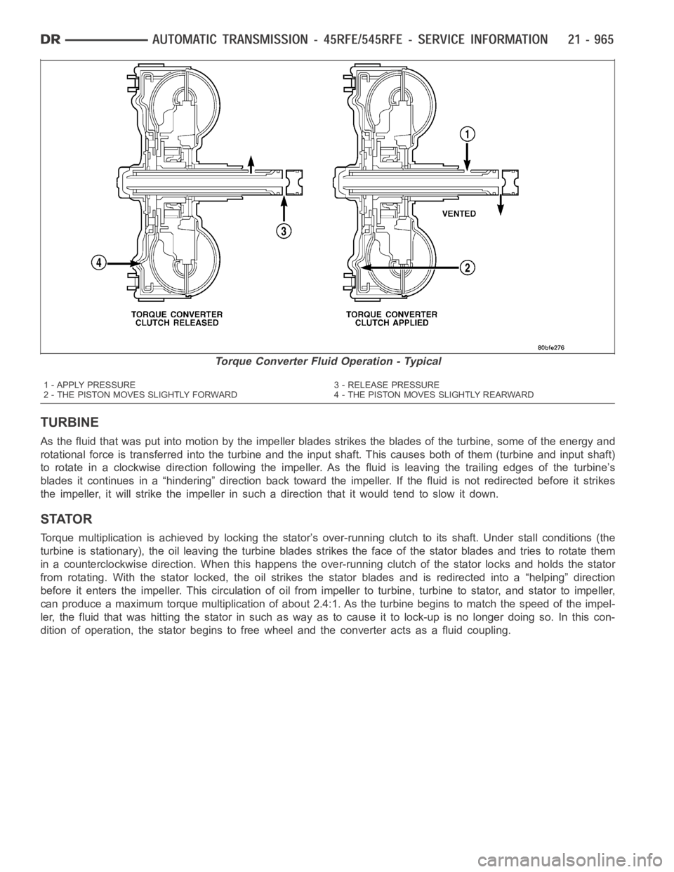
Torque Converter Fluid Operation - Typical
1 - APPLY PRESSURE 3 - RELEASE PRESSURE
2 - THE PISTON MOVES SLIGHTLY FORWARD 4 - THE PISTON MOVES SLIGHTLY REARWARD
Page 3487 of 5267
TORQUE CONVERTER CLUTCH (TCC)
In a standard torque converter, the impeller and tur-
bine are rotating at about the same speed and the
stator is freewheeling, providing no torque multiplica-
tion. By applying the turbine’s piston and friction mate-
rial to the front cover, a total converter engagement
can be obtained. The result of this engagement is a
direct 1:1 mechanical link between the engine and the
transmission.
The clutch can be engaged in second, third, fourth,
and fifth (if appicable) gear ranges depending on over-
drive control switch position. If the overdrive control
switch is in the normal ON position, the clutch will
engage after the shift to fourth gear. If the control
switch is in the OFF position, the clutch will engage
after the shift to third gear.
The TCM controls the torque converter by way of
internal logic software. The programming of the soft-
ware provides the TCM with control over the L/R-CC
Solenoid. There are four output logic states that can
be applied as follows:
No EMCC
Partial EMCC
Full EMCC
Gradual-to-no EMCC
NO EMCC
Under No EMCC conditions, the L/R Solenoid is OFF. There are several conditions that can result in NO EMCC
operations. No EMCC can be initiated due to a fault in the transmission or because the TCM does not see the need
for EMCC under current driving conditions.
PARTIAL EMCC
Partial EMCC operation modulates the L/R Solenoid (duty cycle) to obtain partial torque converter clutch application.
Partial EMCC operation is maintaineduntil Full EMCC is called for and actuated. During Partial EMCC some slip
does occur. Partial EMCC will usually occur at low speeds, low load and light throttle situations.
FULL EMCC
During Full EMCC operation, the TCM increases the L/R Solenoid duty cycle to full ON after Partial EMCC control
brings the engine speed within the desired slip range of transmission input speed relative to engine rpm.
GRADUAL-TO-NO EMCC
This operation is to soften the change from Full or Partial EMCC to No EMCC. This is done at mid-throttle by
decreasing the L/R Solenoid duty cycle.
REMOVAL
1. Remove transmission and torque converter from vehicle. (Refer to 21 - TRANSMISSION/AUTOMATIC - 45RFE/
545RFE - REMOVAL)
2. Place a suitable drain pan under the converter housing end of the transmission.
CAUTION: Verify that transmission is secure on the lifting device or work surface, the center of gravity of
the transmission will shift when the torque converter is removed creatingan unstable condition. The torque
converter is a heavy unit. Use caution when separating the torque converter from the transmission.
3. Pull the torque converter forward until the center hub clears the oil pumpseal.
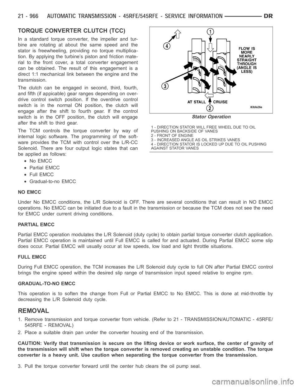
Stator Operation
1 - DIRECTION STATOR WILL FREE WHEEL DUE TO OIL
PUSHING ON BACKSIDE OF VANES
2-FRONTOFENGINE
3 - INCREASED ANGLE AS OIL STRIKES VANES
4 - DIRECTION STATOR IS LOCKED UP DUE TO OIL PUSHING
AGAINST STATOR VANES
Page 3494 of 5267
SENSOR-TRANSMISSION TEMPERATURE
DESCRIPTION
The transmission temperature sensor is a thermistor that is integral to the Transmission Range Sensor (TRS).
OPERATION
The transmission temperature sensor is used by the TCM to sense the temperature of the fluid in the sump. Since
fluid temperature can affect transmission shift quality and convertor lock up, the TCM requires this information to
determine which shift schedule to operate in.
Calculated Temperature
A failure in the temperature sensor or circuit will result in calculated temperature being substituted for actual tem-
perature. Calculated temperature is a predicted fluid temperature whichis calculated from a combination of inputs:
Battery (ambient) temperature
Engine coolant temperature
In-gear run time since start-up
Page 3508 of 5267
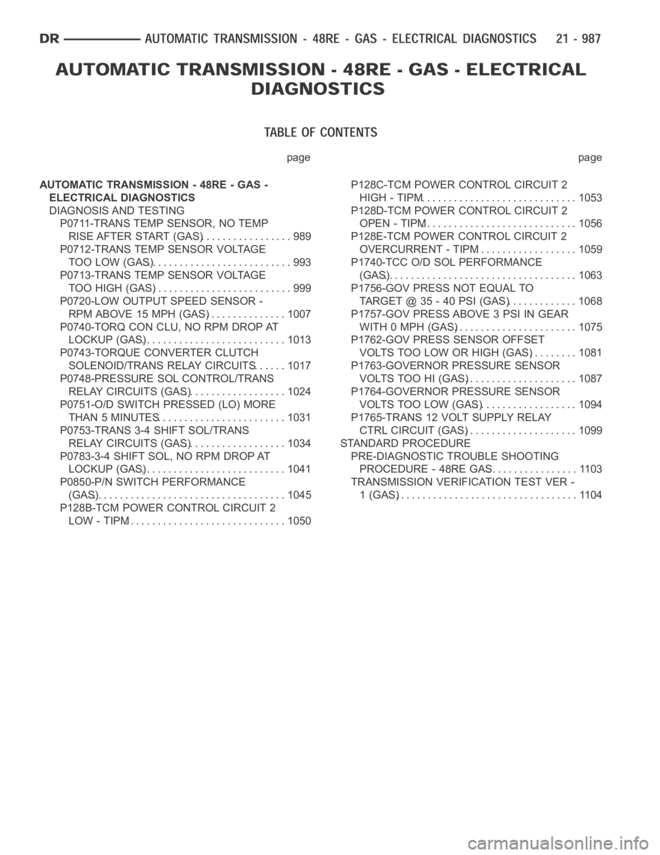
page page
AUTOMATIC TRANSMISSION - 48RE - GAS -
ELECTRICAL DIAGNOSTICS
DIAGNOSIS AND TESTING
P0711-TRANS TEMP SENSOR, NO TEMP
RISE AFTER START (GAS)................. 989
P0712-TRANS TEMP SENSOR VOLTAGE
TOO LOW (GAS)........................... 993
P0713-TRANS TEMP SENSOR VOLTAGE
TOO HIGH (GAS).......................... 999
P0720-LOW OUTPUT SPEED SENSOR -
RPM ABOVE 15 MPH (GAS)............... 1007
P0740-TORQ CON CLU, NO RPM DROP AT
LOCKUP (GAS)........................... 1013
P0743-TORQUE CONVERTER CLUTCH
SOLENOID/TRANS RELAY CIRCUITS. ..... 1017
P0748-PRESSURE SOL CONTROL/TRANS
RELAY CIRCUITS (GAS)................... 1024
P0751-O/D SWITCH PRESSED (LO) MORE
THAN 5 MINUTES........................ 1031
P0753-TRANS 3-4 SHIFT SOL/TRANS
RELAY CIRCUITS (GAS)................... 1034
P0783-3-4 SHIFT SOL, NO RPM DROP AT
LOCKUP (GAS)........................... 1041
P0850-P/N SWITCH PERFORMANCE
(GAS).................................... 1045
P128B-TCM POWER CONTROL CIRCUIT 2
LOW - TIPM.............................. 1050P128C-TCM POWER CONTROL CIRCUIT 2
HIGH - TIPM.............................. 1053
P128D-TCM POWER CONTROL CIRCUIT 2
OPEN - TIPM............................. 1056
P128E-TCM POWER CONTROL CIRCUIT 2
OVERCURRENT - TIPM................... 1059
P1740-TCC O/D SOL PERFORMANCE
(GAS).................................... 1063
P1756-GOV PRESS NOT EQUAL TO
TARGET @ 35 - 40 PSI (GAS)............. 1068
P1757-GOV PRESS ABOVE 3 PSI IN GEAR
WITH 0 MPH (GAS)....................... 1075
P1762-GOV PRESS SENSOR OFFSET
VOLTS TOO LOW OR HIGH (GAS)......... 1081
P1763-GOVERNOR PRESSURE SENSOR
VOLTS TOO HI (GAS)..................... 1087
P1764-GOVERNOR PRESSURE SENSOR
VOLTS TOO LOW (GAS)................... 1094
P1765-TRANS 12 VOLT SUPPLY RELAY
CTRL CIRCUIT (GAS)..................... 1099
STANDARD PROCEDURE
PRE-DIAGNOSTIC TROUBLE SHOOTING
PROCEDURE - 48RE GAS................. 1103
TRANSMISSION VERIFICATION TEST VER -
1(GAS).................................. 1104
Page 3511 of 5267
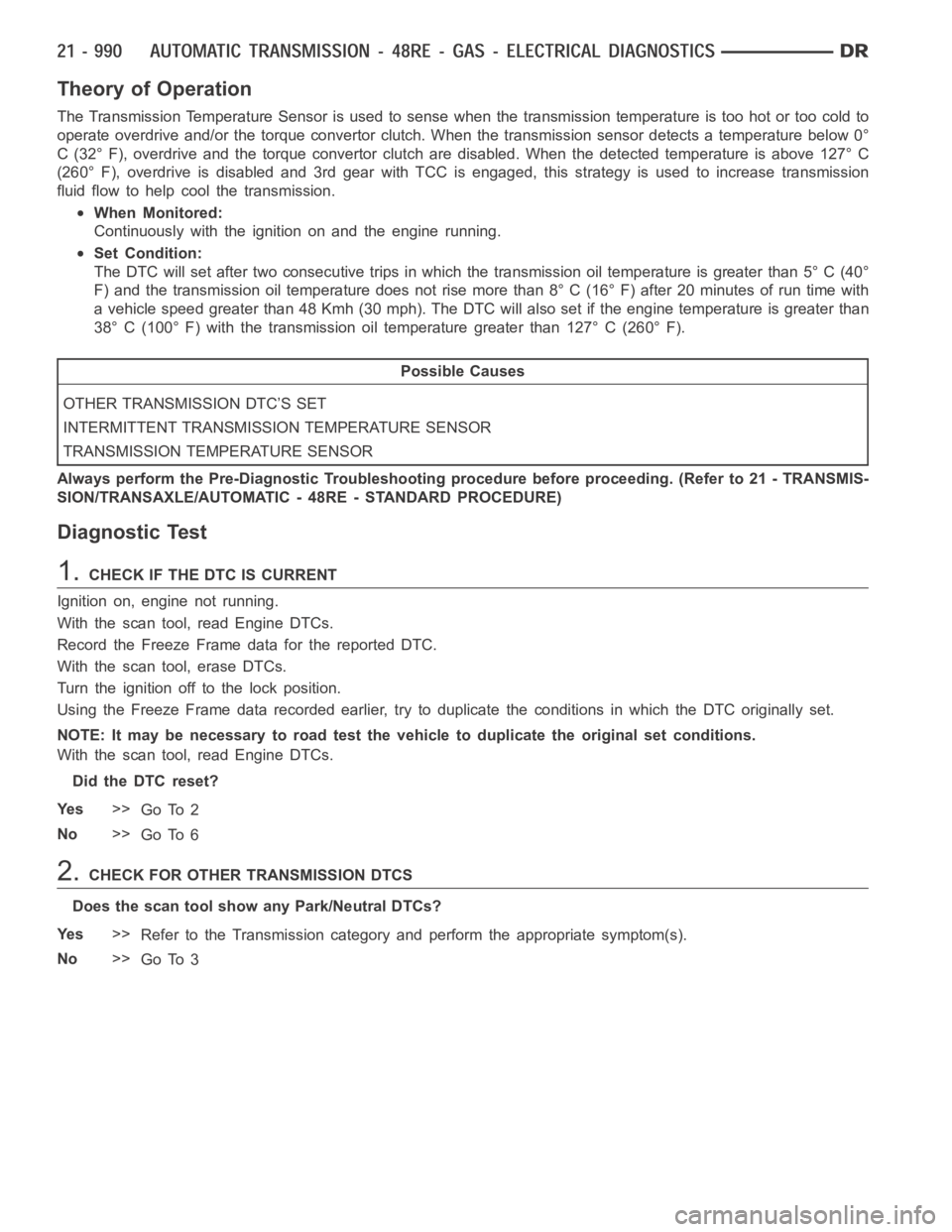
Theory of Operation
The Transmission Temperature Sensor is used to sense when the transmissiontemperatureistoohotortoocoldto
operate overdrive and/or the torque convertor clutch. When the transmission sensor detects a temperature below 0°
C (32° F), overdrive and the torque convertor clutch are disabled. When thedetected temperature is above 127° C
(260° F), overdrive is disabled and 3rd gear with TCC is engaged, this strategy is used to increase transmission
fluid flow to help cool the transmission.
When Monitored:
Continuously with the ignition on and the engine running.
Set Condition:
The DTC will set after two consecutive trips in which the transmission oil temperature is greater than 5° C (40°
F) and the transmission oil temperature does not rise more than 8° C (16° F) after 20 minutes of run time with
a vehicle speed greater than 48 Kmh (30 mph). The DTC will also set if the engine temperature is greater than
38° C (100° F) with the transmission oil temperature greater than 127° C (260° F).
Possible Causes
OTHER TRANSMISSION DTC’S SET
INTERMITTENT TRANSMISSION TEMPERATURE SENSOR
TRANSMISSION TEMPERATURE SENSOR
Always perform the Pre-Diagnostic Troubleshooting procedure before proceeding. (Refer to 21 - TRANSMIS-
SION/TRANSAXLE/AUTOMATIC - 48RE - STANDARD PROCEDURE)
Diagnostic Test
1.CHECK IF THE DTC IS CURRENT
Ignition on, engine not running.
With the scan tool, read Engine DTCs.
Record the Freeze Frame data for the reported DTC.
With the scan tool, erase DTCs.
Turn the ignition off to the lock position.
Using the Freeze Frame data recorded earlier, try to duplicate the conditions in which the DTC originally set.
NOTE: It may be necessary to road test the vehicle to duplicate the originalset conditions.
With the scan tool, read Engine DTCs.
Did the DTC reset?
Ye s>>
Go To 2
No>>
Go To 6
2.CHECK FOR OTHER TRANSMISSION DTCS
Does the scan tool show any Park/Neutral DTCs?
Ye s>>
Refer to the Transmission category and perform the appropriate symptom(s).
No>>
Go To 3
Page 3513 of 5267
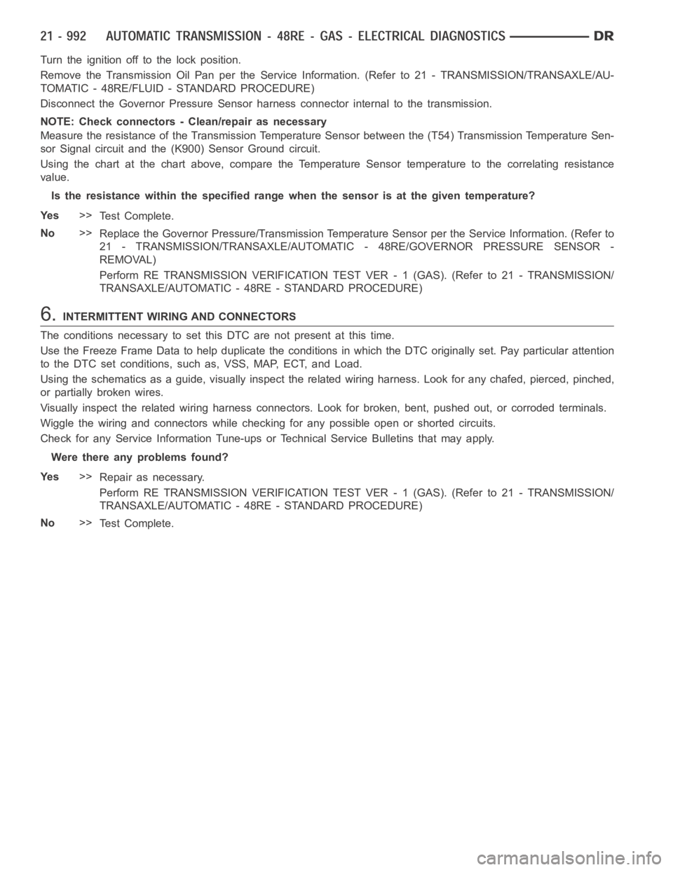
Turn the ignition off to the lock position.
Remove the Transmission Oil Pan per the Service Information. (Refer to 21 -TRANSMISSION/TRANSAXLE/AU-
TOMATIC - 48RE/FLUID - STANDARD PROCEDURE)
Disconnect the Governor Pressure Sensor harness connector internal to the transmission.
NOTE: Check connectors - Clean/repair as necessary
Measure the resistance of the Transmission Temperature Sensor between the (T54) Transmission Temperature Sen-
sor Signal circuit and the (K900) Sensor Ground circuit.
Using the chart at the chart above, compare the Temperature Sensor temperature to the correlating resistance
value.
Is the resistance within the specified range when the sensor is at the giventemperature?
Ye s>>
Te s t C o m p l e t e .
No>>
Replace the Governor Pressure/Transmission Temperature Sensor per the Service Information. (Refer to
21 - TRANSMISSION/TRANSAXLE/AUTOMATIC - 48RE/GOVERNOR PRESSURE SENSOR-
REMOVAL)
Perform RE TRANSMISSION VERIFICATION TEST VER - 1 (GAS). (Refer to 21 - TRANSMISSION/
TRANSAXLE/AUTOMATIC - 48RE - STANDARD PROCEDURE)
6.INTERMITTENT WIRING AND CONNECTORS
The conditions necessary to set this DTC are not present at this time.
Use the Freeze Frame Data to help duplicate the conditions in which the DTC originally set. Pay particular attention
to the DTC set conditions, such as, VSS, MAP, ECT, and Load.
Using the schematics as a guide, visually inspect the related wiring harness. Look for any chafed, pierced, pinched,
or partially broken wires.
Visually inspect the related wiring harness connectors. Look for broken,bent, pushed out, or corroded terminals.
Wiggle the wiring and connectors while checking for any possible open or shorted circuits.
Check for any Service Information Tune-ups or Technical Service Bulletins that may apply.
Were there any problems found?
Ye s>>
Repair as necessary.
Perform RE TRANSMISSION VERIFICATION TEST VER - 1 (GAS). (Refer to 21 - TRANSMISSION/
TRANSAXLE/AUTOMATIC - 48RE - STANDARD PROCEDURE)
No>>
Te s t C o m p l e t e .
Page 3515 of 5267
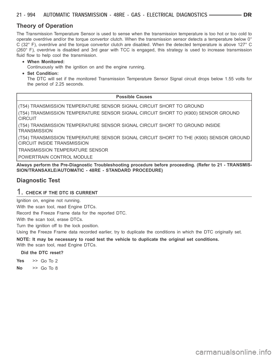
Theory of Operation
The Transmission Temperature Sensor is used to sense when the transmissiontemperatureistoohotortoocoldto
operate overdrive and/or the torque convertor clutch. When the transmission sensor detects a temperature below 0°
C (32° F), overdrive and the torque convertor clutch are disabled. When thedetected temperature is above 127° C
(260° F), overdrive is disabled and 3rd gear with TCC is engaged, this strategy is used to increase transmission
fluid flow to help cool the transmission.
When Monitored:
Continuously with the ignition on and the engine running.
Set Condition:
The DTC will set if the monitored Transmission Temperature Sensor Signal circuit drops below 1.55 volts for
the period of 2.25 seconds.
Possible Causes
(T54) TRANSMISSION TEMPERATURE SENSOR SIGNAL CIRCUIT SHORT TO GROUND
(T54) TRANSMISSION TEMPERATURE SENSOR SIGNAL CIRCUIT SHORT TO (K900) SENSOR GROUND
CIRCUIT
(T54) TRANSMISSION TEMPERATURE SENSOR SIGNAL CIRCUIT SHORT TO GROUND INSIDE
TRANSMISSION
(T54) TRANSMISSION TEMPERATURE SENSOR SIGNAL CIRCUIT SHORT TO THE (K900)SENSOR GROUND
CIRCUIT INSIDE TRANSMISSION
TRANSMISSION TEMPERATURE SENSOR
POWERTRAIN CONTROL MODULE
Always perform the Pre-Diagnostic Troubleshooting procedure before proceeding. (Refer to 21 - TRANSMIS-
SION/TRANSAXLE/AUTOMATIC - 48RE - STANDARD PROCEDURE)
Diagnostic Test
1.CHECK IF THE DTC IS CURRENT
Ignition on, engine not running.
With the scan tool, read Engine DTCs.
Record the Freeze Frame data for the reported DTC.
With the scan tool, erase DTCs.
Turn the ignition off to the lock position.
Using the Freeze Frame data recorded earlier, try to duplicate the conditions in which the DTC originally set.
NOTE: It may be necessary to road test the vehicle to duplicate the originalset conditions.
With the scan tool, read Engine DTCs.
Did the DTC reset?
Ye s>>
Go To 2
No>>
Go To 8