Page 3392 of 5267
INSTALLATION
1. Check torque converter hub and hub drive flats for
sharp edges burrs, scratches, or nicks. Polish the
hub and flats with 320/400 grit paper and crocus
cloth if necessary. Verify that the converter hub
o-ring is properly installed and is free of any debris.
The hub must be smooth to avoid damaging pump
seal at installation.
2. If a replacement transmission is being installed,
transfer any components necessary, such as the
manual shift lever and shift cable bracket, from the
original transmission onto the replacement trans-
mission.
3. Lubricate oil pump seal lip with transmission fluid.
4. Align converter and oil pump.
5. Carefully insert converter in oil pump. Then rotate
converter back and forth until fully seated in pump
gears.
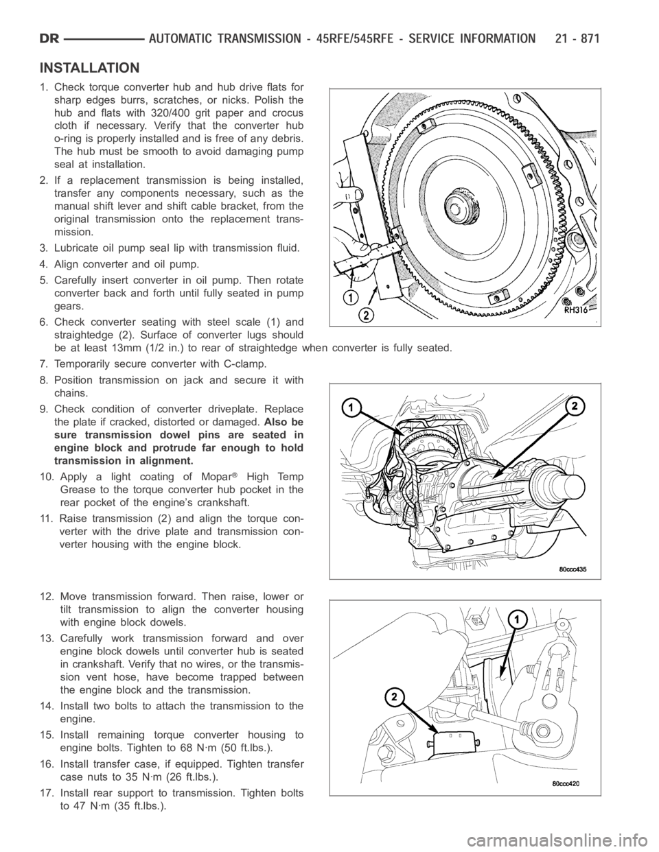
6. Check converter seating with steel scale (1) and
straightedge (2). Surface of converter lugs should
be at least 13mm (1/2 in.) to rear of straightedge when converter is fully seated.
7. Temporarily secure converter with C-clamp.
8. Position transmission on jack and secure it with
chains.
9. Check condition of converter driveplate. Replace
the plate if cracked, distorted or damaged.Also be
sure transmission dowel pins are seated in
engine block and protrude far enough to hold
transmission in alignment.
10. Apply a light coating of Mopar
High Temp
Grease to the torque converter hub pocket in the
rear pocket of the engine’s crankshaft.
11. Raise transmission (2) and align the torque con-
verter with the drive plate and transmission con-
verter housing with the engine block.
12. Move transmission forward. Then raise, lower or
tilt transmission to align the converter housing
with engine block dowels.
13. Carefully work transmission forward and over
engine block dowels until converter hub is seated
in crankshaft. Verify that no wires, or the transmis-
sion vent hose, have become trapped between
theengineblockandthetransmission.
14. Install two bolts to attach the transmission to the
engine.
15. Install remaining torque converter housing to
engine bolts. Tighten to 68 Nꞏm (50 ft.lbs.).
16. Install transfer case, if equipped. Tighten transfer
case nuts to 35 Nꞏm (26 ft.lbs.).
17. Install rear support to transmission. Tighten bolts
to 47 Nꞏm (35 ft.lbs.).
Page 3394 of 5267
CAUTION: It is essential that correct length bolts
be used to attach the converter to the driveplate.
Bolts that are too long will damage the clutch sur-
face inside the converter.
25. Install torque converter-to-driveplate bolts. Tighten
boltsto31Nꞏm(270in.lbs.).
26. Install starter motor and cooler line bracket.
27. Connect cooler lines to transmission.
28. Install transmission fill tube.
29. Install exhaust components, if necessary.
30. Install the structural dust cover (2) (Refer to 9 -
ENGINE/ENGINE BLOCK/STRUCTURAL COVER
- INSTALLATION) onto the transmission and the
engine.
31. Align and connect propeller shaft(s).
32. Adjust gearshift cable if necessary.
33. Install any skid plates removed previously. (Refer
to 13 - FRAMES & BUMPERS/FRAME/TRANS-
FER CASE SKID PLATE - INSTALLATION)
34. Lower vehicle.
35. Fill transmission with Mopar
ATF +4, Automatic Transmission Fluid.
Page 3399 of 5267
HYDRAULIC FLOW IN REVERSE BLOCK
Page 3428 of 5267
SYSTEM-BRAKE TRANSMISSION SHIFT INTERLOCK
DESCRIPTION
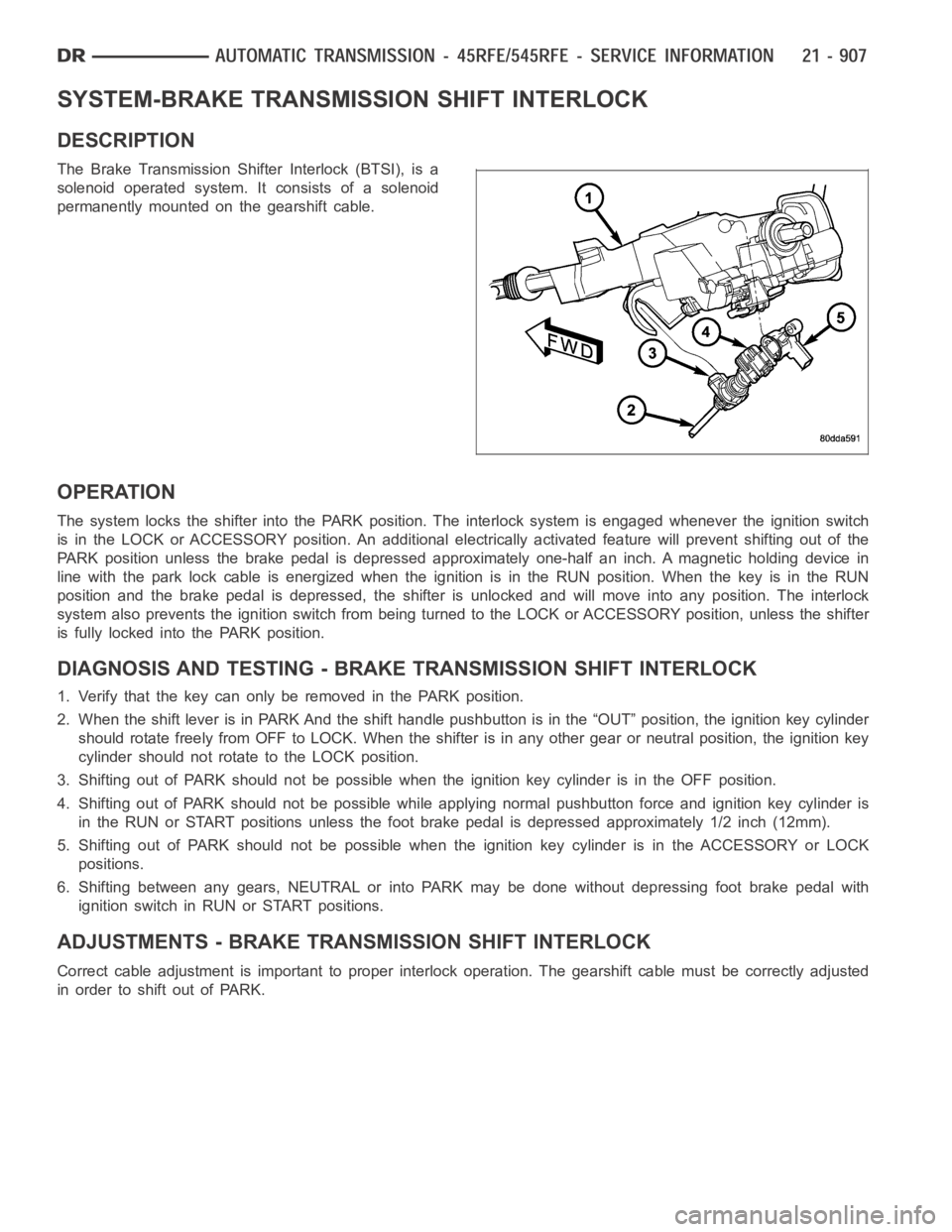
The Brake Transmission Shifter Interlock (BTSI), is a
solenoid operated system. It consists of a solenoid
permanently mounted on the gearshift cable.
OPERATION
The system locks the shifter into the PARK position. The interlock system is engaged whenever the ignition switch
is in the LOCK or ACCESSORY position. An additional electrically activated feature will prevent shifting out of the
PARK position unless the brake pedal is depressed approximately one-halfan inch. A magnetic holding device in
line with the park lock cable is energized when the ignition is in the RUN position. When the key is in the RUN
position and the brake pedal is depressed, the shifter is unlocked and willmove into any position. The interlock
system also prevents the ignition switch from being turned to the LOCK or ACCESSORY position, unless the shifter
is fully locked into the PARK position.
DIAGNOSIS AND TESTING - BRAKE TRANSMISSION SHIFT INTERLOCK
1. Verify that the key can only be removed in the PARK position.
2. When the shift lever is in PARK And the shift handle pushbutton is in the “OUT” position, the ignition key cylinder
should rotate freely from OFF to LOCK. When the shifter is in any other gear or neutral position, the ignition key
cylinder should not rotate to the LOCK position.
3. Shifting out of PARK should not be possible when the ignition key cylinder is in the OFF position.
4. Shifting out of PARK should not be possible while applying normal pushbutton force and ignition key cylinder is
in the RUN or START positions unless the foot brake pedal is depressed approximately 1/2 inch (12mm).
5. Shifting out of PARK should not be possible when the ignition key cylinderisintheACCESSORYorLOCK
positions.
6. Shifting between any gears, NEUTRAL or into PARK may be done without depressing foot brake pedal with
ignition switch in RUN or START positions.
ADJUSTMENTS - BRAKE TRANSMISSION SHIFT INTERLOCK
Correct cable adjustment is important to proper interlock operation. Thegearshift cable must be correctly adjusted
in order to shift out of PARK.
Page 3429 of 5267
ADJUSTMENT PROCEDURE
1. Remove the steering column trim as necessary for
access to the brake transmission shift interlock.
2. Shift the transmission into the PARK position.
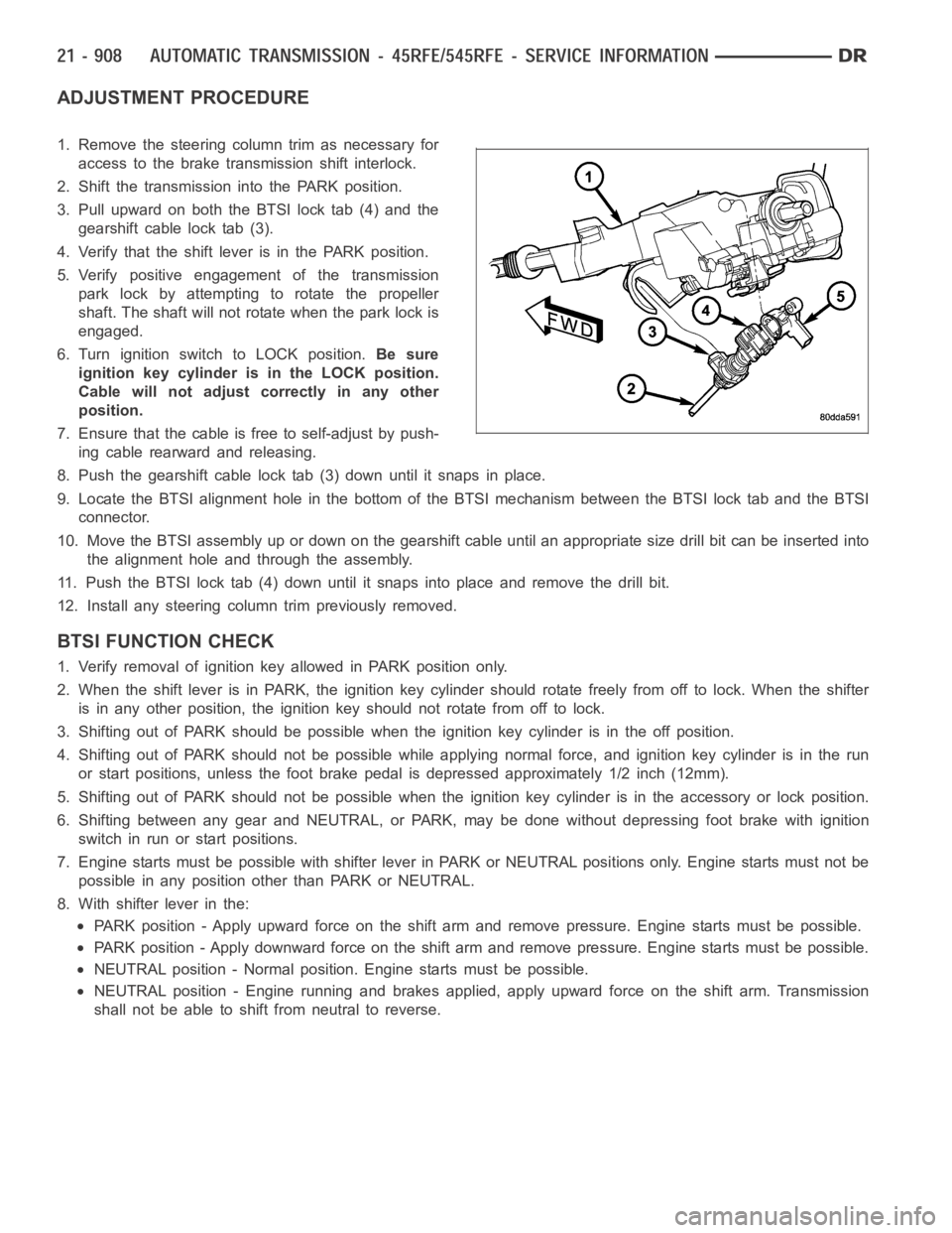
3. Pull upward on both the BTSI lock tab (4) and the
gearshift cable lock tab (3).
4. Verify that the shift lever is in the PARK position.
5. Verify positive engagement of the transmission
park lock by attempting to rotate the propeller
shaft. The shaft will not rotate when the park lock is
engaged.
6. Turn ignition switch to LOCK position.Be sure
ignition key cylinder is in the LOCK position.
Cable will not adjust correctly in any other
position.
7. Ensure that the cable is free to self-adjust by push-
ing cable rearward and releasing.
8. Push the gearshift cable lock tab (3) down until it snaps in place.
9. Locate the BTSI alignment hole in the bottom of the BTSI mechanism betweentheBTSIlocktabandtheBTSI
connector.
10. Move the BTSI assembly up or down on the gearshift cable until an appropriate size drill bit can be inserted into
the alignment hole and through the assembly.
11. Push the BTSI lock tab (4) down until it snaps into place and remove the drill bit.
12. Install any steering column trim previously removed.
BTSI FUNCTION CHECK
1. Verify removal of ignition key allowed in PARK position only.
2. When the shift lever is in PARK, the ignition key cylinder should rotate freely from off to lock. When the shifter
is in any other position, the ignition key should not rotate from off to lock.
3. Shifting out of PARK should be possible when the ignition key cylinder isin the off position.
4. Shifting out of PARK should not be possible while applying normal force,and ignition key cylinder is in the run
or start positions, unless the foot brake pedal is depressed approximately1/2inch(12mm).
5. Shifting out of PARK should not be possible when the ignition key cylinder is in the accessory or lock position.
6. Shifting between any gear and NEUTRAL, or PARK, may be done without depressing foot brake with ignition
switch in run or start positions.
7. Engine starts must be possible with shifter lever in PARK or NEUTRAL positions only. Engine starts must not be
possible in any position other than PARK or NEUTRAL.
8. With shifter lever in the:
PARK position - Apply upward force on the shift arm and remove pressure. Enginestartsmustbepossible.
PARK position - Apply downward force on the shift arm and remove pressure. Engine starts must be possible.
NEUTRAL position - Normal position. Engine starts must be possible.
NEUTRAL position - Engine running and brakes applied, apply upward force on the shift arm. Transmission
shall not be able to shift from neutral to reverse.
Page 3435 of 5267
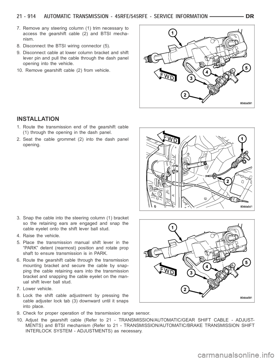
7. Remove any steering column (1) trim necessary to
access the gearshift cable (2) and BTSI mecha-
nism.
8. Disconnect the BTSI wiring connector (5).
9. Disconnect cable at lower column bracket and shift
lever pin and pull the cable through the dash panel
opening into the vehicle.
10. Remove gearshift cable (2) from vehicle.
INSTALLATION
1. Route the transmission end of the gearshift cable
(1) through the opening in the dash panel.
2. Seat the cable grommet (2) into the dash panel
opening.
3. Snap the cable into the steering column (1) bracket
so the retaining ears are engaged and snap the
cable eyelet onto the shift lever ball stud.
4. Raise the vehicle.
5. Place the transmission manual shift lever in the
“PARK” detent (rearmost) position and rotate prop
shaft to ensure transmission is in PARK.
6. Route the gearshift cable through the transmission
mounting bracket and secure the cable by snap-
ping the cable retaining ears into the transmission
bracket and snapping the cable eyelet on the man-
ual shift lever ball stud.
7. Lower vehicle.
8. Lock the shift cable adjustment by pressing the
cable adjuster lock tab (3) downward until it snaps
into place.
9. Check for proper operation of the transmission range sensor.
10. Adjust the gearshift cable (Refer to 21 - TRANSMISSION/AUTOMATIC/GEAR SHIFT CABLE - ADJUST-
MENTS) and BTSI mechanism (Refer to 21 - TRANSMISSION/AUTOMATIC/BRAKE TRANSMISSION SHIFT
INTERLOCK SYSTEM - ADJUSTMENTS) as necessary.
Page 3436 of 5267
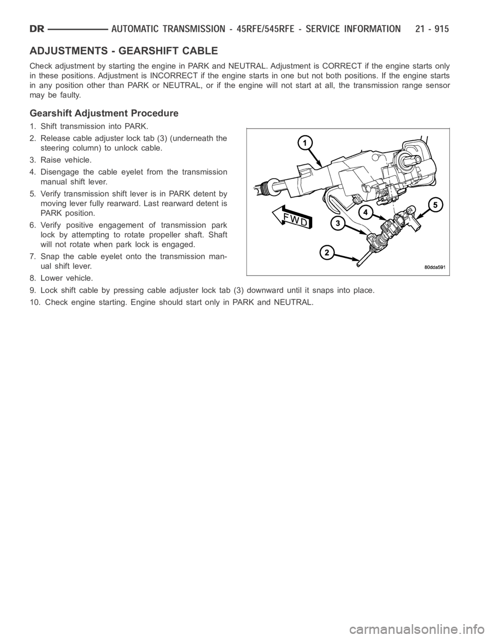
ADJUSTMENTS - GEARSHIFT CABLE
Check adjustment by starting the engine in PARK and NEUTRAL. Adjustment isCORRECT if the engine starts only
in these positions. Adjustment is INCORRECT if the engine starts in one butnot both positions. If the engine starts
in any position other than PARK or NEUTRAL, or if the engine will not start atall, the transmission range sensor
may be faulty.
Gearshift Adjustment Procedure
1. Shift transmission into PARK.
2. Release cable adjuster lock tab (3) (underneath the
steering column) to unlock cable.
3. Raise vehicle.
4. Disengage the cable eyelet from the transmission
manual shift lever.
5. Verify transmission shift lever is in PARK detent by
moving lever fully rearward. Last rearward detent is
PARK position.
6. Verify positive engagement of transmission park
lock by attempting to rotate propeller shaft. Shaft
will not rotate when park lock is engaged.
7. Snap the cable eyelet onto the transmission man-
ual shift lever.
8. Lower vehicle.
9. Lock shift cable by pressing cable adjuster lock tab (3) downward until it snaps into place.
10. Check engine starting. Engine should start only in PARK and NEUTRAL.
Page 3484 of 5267
STATOR
The stator assembly is mounted on a stationary shaft
which is an integral part of the oil pump. The stator (1)
islocatedbetweentheimpeller (2) and the turbine (4)
within the torque converter case.
The stator contains an over-running clutch (1-4), which
allows the stator to rotate only in a clockwise direction.
When the stator is locked against the over-running
clutch, the torque multiplication feature of the torque
converter is operational.