2006 DODGE RAM SRT-10 automatic transmission
[x] Cancel search: automatic transmissionPage 3943 of 5267
MECHANISM-SHIFT
DESCRIPTION
The gear shift mechanism provides six shift positions which are:
PA R K ( P )
REVERSE (R)
NEUTRAL (N)
DRIVE (D)
Manual SECOND (2)
Manual LOW (1)
OPERATION
Manual LOW (1) range provides first gear only. Overrun braking is also provided in this range. Manual SECOND (2)
range provides first and second gear only.
DRIVE range provides first, second, third, and overdrive fourth gear ranges. The shift into overdrive fourth gear
range occurs only after the transmission has completed the shift into D third gear range. No further movement of the
shift mechanism is required to complete the 3-4 shift.
The fourth gear upshift occurs automatically when the overdrive selectorswitch is in the ON position. No upshift to
fourth gear will occur if any of the following are true:
The transmission fluid temperature is below 10° C (50° F) or above 121° C (250° F).
The shift to third is not yet complete.
Vehicle speed is too low for the 3-4 shift to occur.
Battery temperature is below -5° C (23° F).
Page 3947 of 5267
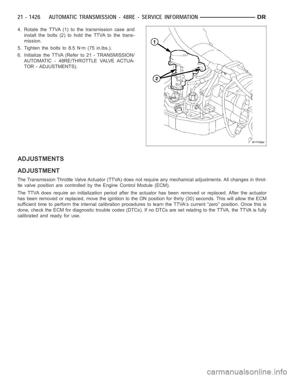
4. Rotate the TTVA (1) to the transmission case and
install the bolts (2) to hold the TTVA to the trans-
mission.
5. Tighten the bolts to 8.5 Nꞏm (75 in.lbs.).
6. Initialize the TTVA (Refer to 21 - TRANSMISSION/
AUTOMATIC - 48RE/THROTTLE VALVE ACTUA-
TOR - ADJUSTMENTS).
ADJUSTMENTS
ADJUSTMENT
The Transmission Throttle Valve Actuator (TTVA) does not require any mechanical adjustments. All changes in throt-
tle valve position are controlled by the Engine Control Module (ECM).
The TTVA does require an initialization period after the actuator has beenremoved or replaced. After the actuator
has been removed or replaced, move the iginition to the ON position for thirty (30) seconds. This will allow the ECM
sufficient time to perform the internal calibration procedures to learn the TTVA’s current “zero” position. Once this is
done, check the ECM for diagnostic trouble codes (DTCs). If no DTCs are set relating to the TTVA, the TTVA is fully
calibrated and ready for use.
Page 3957 of 5267
STATOR
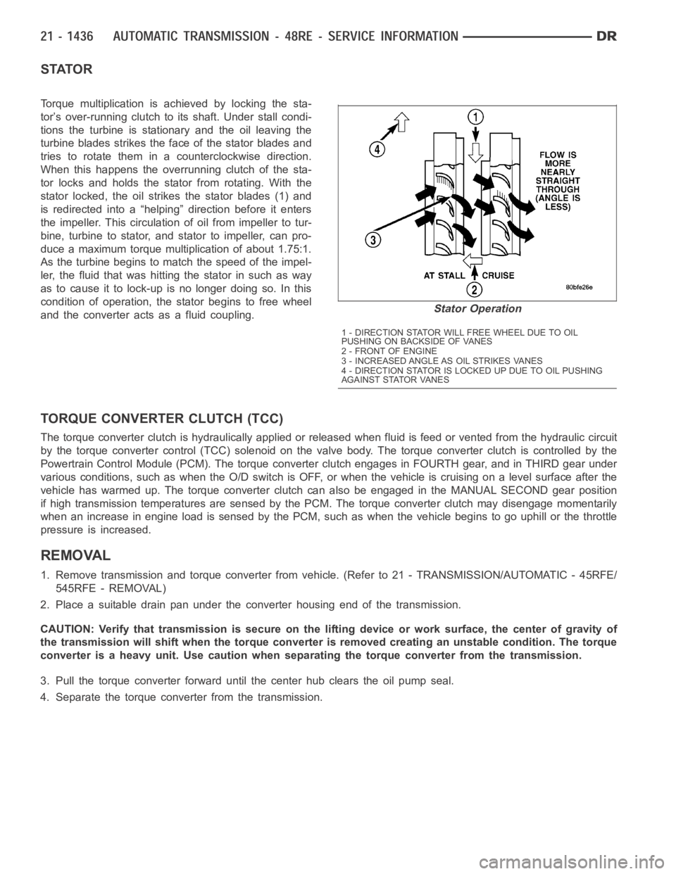
Torque multiplication is achieved by locking the sta-
tor’s over-running clutch to its shaft. Under stall condi-
tions the turbine is stationary and the oil leaving the
turbine blades strikes the face of the stator blades and
tries to rotate them in a counterclockwise direction.
When this happens the overrunning clutch of the sta-
tor locks and holds the stator from rotating. With the
stator locked, the oil strikes the stator blades (1) and
is redirected into a “helping” direction before it enters
the impeller. This circulation of oil from impeller to tur-
bine, turbine to stator, and stator to impeller, can pro-
duce a maximum torque multiplication of about 1.75:1.
As the turbine begins to match the speed of the impel-
ler, the fluid that was hitting the stator in such as way
as to cause it to lock-up is no longer doing so. In this
condition of operation, the stator begins to free wheel
and the converter acts as a fluid coupling.
TORQUE CONVERTER CLUTCH (TCC)
The torque converter clutch is hydraulically applied or released when fluid is feed or vented from the hydraulic circuit
by the torque converter control (TCC) solenoid on the valve body. The torque converter clutch is controlled by the
Powertrain Control Module (PCM). The torque converter clutch engages in FOURTH gear, and in THIRD gear under
various conditions, such as when the O/D switch is OFF, or when the vehicle is cruising on a level surface after the
vehicle has warmed up. The torque converter clutch can also be engaged in the MANUAL SECOND gear position
if high transmission temperatures are sensed by the PCM. The torque converter clutch may disengage momentarily
when an increase in engine load is sensed by the PCM, such as when the vehiclebegins to go uphill or the throttle
pressure is increased.
REMOVAL
1. Remove transmission and torque converter from vehicle. (Refer to 21 - TRANSMISSION/AUTOMATIC - 45RFE/
545RFE - REMOVAL)
2. Place a suitable drain pan under the converter housing end of the transmission.
CAUTION: Verify that transmission is secure on the lifting device or work surface, the center of gravity of
the transmission will shift when the torque converter is removed creatingan unstable condition. The torque
converter is a heavy unit. Use caution when separating the torque converter from the transmission.
3. Pull the torque converter forward until the center hub clears the oil pumpseal.
4. Separate the torque converter from the transmission.
Stator Operation
1 - DIRECTION STATOR WILL FREE WHEEL DUE TO OIL
PUSHING ON BACKSIDE OF VANES
2-FRONTOFENGINE
3 - INCREASED ANGLE AS OIL STRIKES VANES
4 - DIRECTION STATOR IS LOCKED UP DUE TO OIL PUSHING
AGAINST STATOR VANES
Page 3993 of 5267
Manual lever detent ball.
Throttle lever.
Fluid filter.
Pressure adjusting screw bracket.
Governor pressure solenoid.
Governor pressure sensor (includes transmission temperature thermistor).
Converter clutch/overdrive solenoid assembly and harness.
Governor housing gasket.
Solenoid case connector O-rings.
1. Shift transmission into NEUTRAL.
2. Raise vehicle.
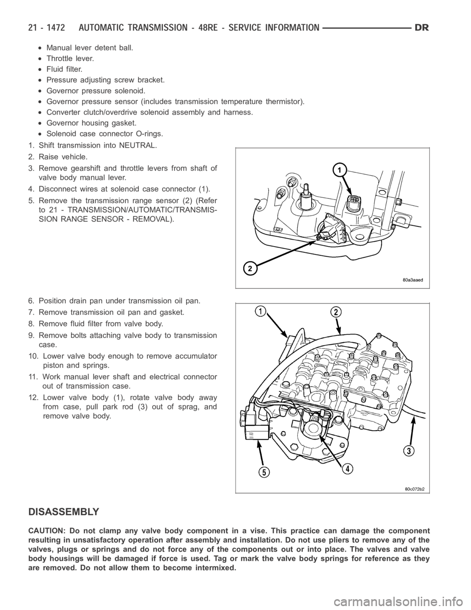
3. Remove gearshift and throttle levers from shaft of
valve body manual lever.
4. Disconnect wires at solenoid case connector (1).
5. Remove the transmission range sensor (2) (Refer
to 21 - TRANSMISSION/AUTOMATIC/TRANSMIS-
SION RANGE SENSOR - REMOVAL).
6. Position drain pan under transmission oil pan.
7. Remove transmission oil pan and gasket.
8. Remove fluid filter from valve body.
9. Remove bolts attaching valve body to transmission
case.
10. Lower valve body enough to remove accumulator
piston and springs.
11. Work manual lever shaft and electrical connector
out of transmission case.
12. Lower valve body (1), rotate valve body away
from case, pull park rod (3) out of sprag, and
remove valve body.
DISASSEMBLY
CAUTION: Do not clamp any valve body component in a vise. This practice can damage the component
resulting in unsatisfactory operation after assembly and installation.Do not use pliers to remove any of the
valves, plugs or springs and do not force any of the components out or into place. The valves and valve
body housings will be damaged if force is used. Tag or mark the valve body springs for reference as they
are removed. Do not allow them to become intermixed.
Page 4017 of 5267
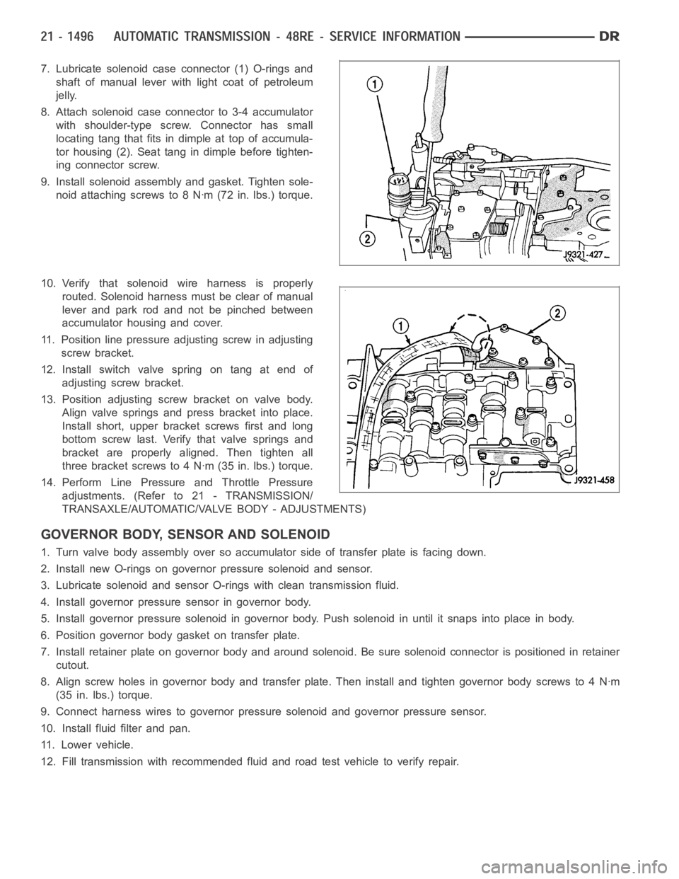
7. Lubricate solenoid case connector (1) O-rings and
shaft of manual lever with light coat of petroleum
jelly.
8. Attach solenoid case connector to 3-4 accumulator
with shoulder-type screw. Connector has small
locating tang that fits indimple at top of accumula-
tor housing (2). Seat tang in dimple before tighten-
ing connector screw.
9. Install solenoid assembly and gasket. Tighten sole-
noid attaching screws to 8 Nꞏm (72 in. lbs.) torque.
10. Verify that solenoid wire harness is properly
routed. Solenoid harness must be clear of manual
lever and park rod and not be pinched between
accumulator housing and cover.
11. Position line pressure adjusting screw in adjusting
screw bracket.
12. Install switch valve spring on tang at end of
adjusting screw bracket.
13. Position adjusting screw bracket on valve body.
Align valve springs and press bracket into place.
Install short, upper bracket screws first and long
bottom screw last. Verify that valve springs and
bracket are properly aligned. Then tighten all
three bracket screws to 4 Nꞏm (35 in. lbs.) torque.
14. Perform Line Pressure and Throttle Pressure
adjustments. (Refer to 21 - TRANSMISSION/
TRANSAXLE/AUTOMATIC/VALVE BODY - ADJUSTMENTS)
GOVERNOR BODY, SENSOR AND SOLENOID
1. Turn valve body assembly over so accumulator side of transfer plate is facing down.
2. Install new O-rings on governor pressure solenoid and sensor.
3. Lubricate solenoid and sensor O-rings with clean transmission fluid.
4. Install governor pressure sensor in governor body.
5. Install governor pressure solenoid in governor body. Push solenoid in until it snaps into place in body.
6. Position governor body gasket on transfer plate.
7. Install retainer plate on governor body and around solenoid. Be sure solenoid connector is positioned in retainer
cutout.
8. Align screw holes in governor body and transfer plate. Then install and tighten governor body screws to 4 Nꞏm
(35 in. lbs.) torque.
9. Connect harness wires to governor pressure solenoid and governor pressure sensor.
10. Install fluid filter and pan.
11. Lower vehicle.
12. Fill transmission with recommended fluid and road test vehicle to verify repair.
Page 4018 of 5267
INSTALLATION
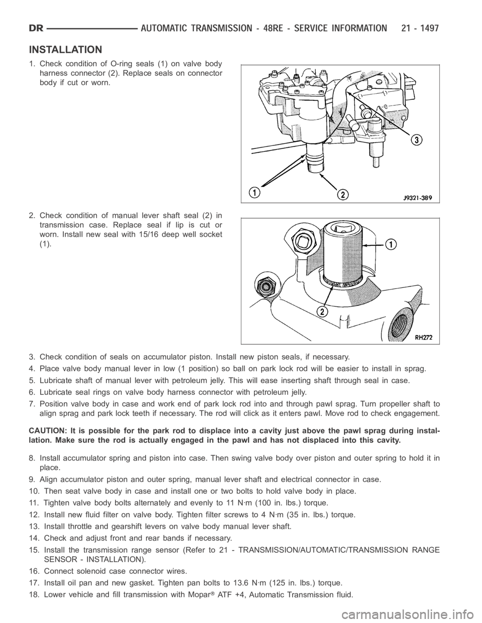
1. Check condition of O-ring seals (1) on valve body
harness connector (2). Replace seals on connector
body if cut or worn.
2. Check condition of manual lever shaft seal (2) in
transmission case. Replace seal if lip is cut or
worn. Install new seal with 15/16 deep well socket
(1).
3. Check condition of seals on accumulator piston. Install new piston seals, if necessary.
4. Place valve body manual lever in low (1 position) so ball on park lock rod will be easier to install in sprag.
5. Lubricate shaft of manual lever with petroleum jelly. This will ease inserting shaft through seal in case.
6. Lubricate seal rings on valve body harness connector with petroleum jelly.
7. Position valve body in case and work end of park lock rod into and through pawl sprag. Turn propeller shaft to
align sprag and park lock teeth if necessary. The rod will click as it enterspawl. Move rod to check engagement.
CAUTION: It is possible for the park rod to displace into a cavity just abovethe pawl sprag during instal-
lation. Make sure the rod is actually engaged in the pawl and has not displaced into this cavity.
8. Install accumulator spring and piston into case. Then swing valve body overpistonandouterspringtoholditin
place.
9. Align accumulator piston and outer spring, manual lever shaft and electrical connector in case.
10. Then seat valve body in case and install one or two bolts to hold valve bodyinplace.
11. Tighten valve body bolts alternately and evenly to 11 Nꞏm (100 in. lbs.)torque.
12. Install new fluid filter on valve body. Tighten filter screws to 4 Nꞏm (35 in. lbs.) torque.
13. Install throttle and gearshift levers on valve body manual lever shaft.
14. Check and adjust front and rear bands if necessary.
15. Install the transmission range sensor (Refer to 21 - TRANSMISSION/AUTOMATIC/TRANSMISSION RANGE
SENSOR - INSTALLATION).
16. Connect solenoid case connector wires.
17. Install oil pan and new gasket. Tighten pan bolts to 13.6 Nꞏm (125 in. lbs.) torque.
18. Lower vehicle and fill transmission with Mopar
ATF +4, Automatic Transmission fluid.
Page 4083 of 5267
TRANSFER CASE VERIFICATION TEST
1.
Disconnect all jumper wires and reconnect all previously disconnected components and connectors.
With the scan tool, select clear Stored DTCs.
Make sure that all accessories are turned off and that the battery is fully charged.
Test drive the vehicle in each Transfer Case range and verify proper operation in each range.
To select or deselect 2WD, AWD or 4HI mode, vehicle speed must be below 88 Kmh(55 mph) with all wheels
at vehicle speed.
Shifts will not take place with a wheel speed difference of greater than 21 Kmh (13 mph) between the front
and rear wheels.
To select or deselect 4LO (if equipped), vehicle speed must be below 5 Kmh (3mph) with the ignition ON and
the transmission in neutral (auto trans) or the clutch pedal pressed (man trans).
To select or deselect Transfer Case Neutral, vehicle speed must be 0 Kmh (0 mph) with the ignition ON,
engine OFF, the brake pedal applied, and the transmission in neutral (autotrans) or the clutch pedal pressed
(man trans). Press the Neutral button (if equipped) on the Transfer Case Selector Switch until the Neutral Indi-
cator is illuminated.
WARNING: Apply the parking brake. The vehicle may roll with the Transfer Case in neutral.
To verify that the Transfer Case is in Neutral, shift the automatic transmission into reverse and release the
brake pedal for three seconds or shift the manual transmission into gear andslowlyreleasetheclutchpedal.
There should be no vehicle movement if the Transfer Case is in Neutral.
With the scan tool, select View DTCs in the Totally Integrated Power Module(TIPM) and in the Instrument Cluster.
Are there any DTCs present in the Totally Integrated Power Module (TIPM) orin the Instrument Cluster?
Ye s>>
Return to the symptom list and perform the appropriate diagnostic test.
No>>
Repair is complete.
Page 4086 of 5267
A straight line shift pattern is used with a NEUTRAL detent. Lever range positions are imprinted in the shift knob.
SHIFTING
The transfer case can be shifted between the 2H and 4H operating ranges while the vehicle is in motion. The vehi-
cle must have the transmission placed in NEUTRAL, or the clutch depressed in the case of a manual transmission,
and be moving less than 2-3 MPH when shifting into and out of the 4L operatingrange.
DIAGNOSIS AND TESTING - TRANSFER CASE - NV241 GENII
Before beginning repair on a suspected transfer case malfunction, check all other driveline components beforehand.
The actual cause of a problem may be related to such items as: front hubs, axles, propeller shafts, wheels and tires,
transmission, or clutch instead. If all other driveline components are ingood condition and operating properly, refer
to the Diagnosis Chart for further information.
DIAGNOSIS CHART
Condition Possible Cause Correction
Transfer Case difficult to shift or will
not shift into desired range.1) Vehicle speed too great to permit
shifting.1) Stop vehicle and shift into
desired range. Or, reduce speed to
below 3-4 km/h (2-3 mph) before
attempting the shift.
2) If vehicle was operated for an
extended period in 4H on a dry
paved surface, the driveline torque
load may be causing a bind.2) Stop vehicle and shift the
transmission into neutral. Shift the
transfer case to 2H and operate
vehicle in 2H on dry paved
surfaces.
3) Transfer case external shift
linkage binding.3) Lubricate, repair, or replace
linkage bushings, or tighten loose
components as necessary.
4) Insufficient or incorrect lubricant. 4) Drain and refill to edge of fillhole
with Mopar
ATF +4, Automatic
Transmission fluid.
5) Internal components binding,
worn, or damaged.5) Disassemble the transfer case
and replace worn or damaged
components as necessary.
Transfer Case noisy in all operating
ranges.1) Insufficient or incorrect lubricant. 1) Drain and refill to edge of fillhole
with Mopar
ATF +4, Automatic
Transmission fluid.
Noisy in, or jumps out of, four wheel
drive low range.1) Transfer case not completely
engaged in 4L position.1) With the transmission in
NEUTRAL, or the clutch depressed
in the case of a manual
transmission and the vehicle moving
under 3-4 km/h (2-3 mph), shift the
transfer case to NEUTRAL and then
shift into the 4L position.
2) Shift linkage out of adjustment. 2) Adjust linkage.
3) Shift linkage loose or binding. 3) Tighten, lubricate, or repair
linkage as necessary.
4) Range fork damaged, inserts
worn, or fork is binding on the shift
rail.4) Disassemble unit and repair as
necessary.
5) Low range gear worn or
damaged.5) Disassemble unit and repair as
necessary.