2006 DODGE RAM SRT-10 automatic transmission
[x] Cancel search: automatic transmissionPage 3784 of 5267
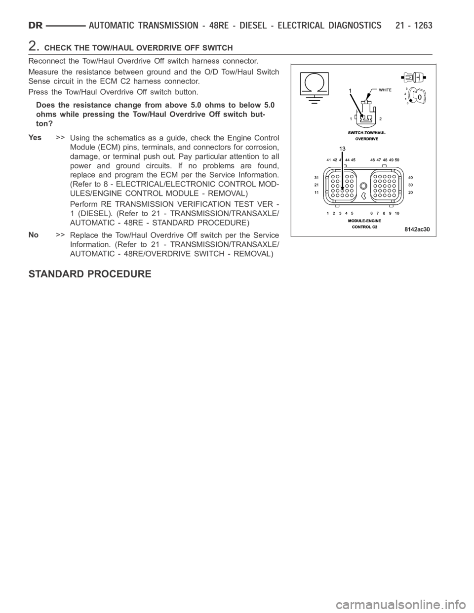
2.CHECK THE TOW/HAUL OVERDRIVE OFF SWITCH
Reconnect the Tow/Haul Overdrive Off switch harness connector.
Measure the resistance between ground and the O/D Tow/Haul Switch
Sense circuit in the ECM C2 harness connector.
Press the Tow/Haul Overdrive Off switch button.
Does the resistance change from above 5.0 ohms to below 5.0
ohms while pressing the Tow/Haul Overdrive Off switch but-
ton?
Ye s>>
Using the schematics as a guide, check the Engine Control
Module (ECM) pins, terminals, and connectors for corrosion,
damage, or terminal push out. Pay particular attention to all
power and ground circuits. If no problems are found,
replace and program the ECM per the Service Information.
(Refer to 8 - ELECTRICAL/ELECTRONIC CONTROL MOD-
ULES/ENGINE CONTROL MODULE - REMOVAL)
Perform RE TRANSMISSION VERIFICATION TEST VER -
1 (DIESEL). (Refer to 21 - TRANSMISSION/TRANSAXLE/
AUTOMATIC - 48RE - STANDARD PROCEDURE)
No>>
Replace the Tow/Haul Overdrive Off switch per the Service
Information. (Refer to 21 - TRANSMISSION/TRANSAXLE/
AUTOMATIC - 48RE/OVERDRIVE SWITCH - REMOVAL)
STANDARD PROCEDURE
Page 3786 of 5267
PRE-DIAGNOSTIC CHECKOUT (DIESEL)
For a complete wiring diagramRefer to Section 8W
1.PRE-DIAGNOSTIC CHECKOUT
NOTE: Always perform diagnostics with a fully charged battery to avoid false symptoms.
NOTE: Low fluid level can be the cause of many transmission problems. If thefluid level is low locate and
repair the leak then check and adjust the fluid level per the Service Information.
With the scan tool, read engine DTC’s. Check and repair all engine DTCs prior to performing transmission symptom
diagnostics.
Using the wiring diagram/schematic as a guide, inspect the wiring and connectors. Repair as necessary.
Verify the flash level of the Engine Control Module. Some problems are corrected by software upgrades.
Check for any Service Information Tune-ups or Technical Service Bulletins that may apply.
Did any of the above checks or procedures correct the symptom?
Ye s>>
Repair is complete.
Perform RE TRANSMISSION VERIFICATION TEST VER - 1 (DIESEL). (Refer to 21 - TRANSMISSION/
TRANSAXLE/AUTOMATIC - 48RE - STANDARD PROCEDURE)
No>>
Refer to the Transmission category and perform the appropriate symptom(s).
Page 3787 of 5267
page page
AUTOMATIC TRANSMISSION - 48RE - SERVICE
INFORMATION
DESCRIPTION ............................. 1268
OPERATION ............................... 1271
DIAGNOSIS AND TESTING
AUTOMATIC TRANSMISSION .............. 1277
PRELIMINARY ............................ 1277
ROAD TESTING .......................... 1277
HYDRAULIC PRESSURE TEST . ........... 1278
AIR TESTING TRANSMISSION CLUTCH
AND BAND OPERATION................... 1281
CONVERTER HOUSING FLUID LEAK ...... 1282
DIAGNOSIS CHARTS ..................... 1283
STANDARD PROCEDURE - ALUMINUM
THREAD REPAIR ......................... 1293
REMOVAL ................................. 1294
DISASSEMBLY ............................. 1298
CLEANING ................................. 1306
INSPECTION ............................... 1306
ASSEMBLY . ............................... 1307
INSTALLATION ............................. 1317
SCHEMATICS AND DIAGRAMS
HYDRAULIC SCHEMATICS ................ 1322
SPECIFICATIONS
TRANSMISSION .......................... 1336
SPECIAL TOOLS
RE TRANSMISSION ...................... 1339
ACCUMULATOR
DESCRIPTION ............................. 1341
OPERATION ............................... 1342
INSPECTION ............................... 1342
BANDS
DESCRIPTION ............................. 1343
OPERATION ............................... 1343
ADJUSTMENTS
ADJUSTMENT - BANDS ................... 1344
SYSTEM-BRAKE TRANSMISSION SHIFT
INTERLOCK
DESCRIPTION ............................. 1345
OPERATION ............................... 1345
DIAGNOSIS AND TESTING - BRAKE
TRANSMISSION SHIFT INTERLOCK ........ 1345
ADJUSTMENTS - BRAKE TRANSMISSION
SHIFT INTERLOCK ....................... 1345
GOVERNOR-ELECTRONIC
DESCRIPTION ............................. 1347
OPERATION ............................... 1348
REMOVAL ................................. 1349
INSTALLATION ............................. 1350SEAL-EXTENSION HOUSING
REMOVAL ................................. 1352
INSTALLATION ............................. 1352
FLUID AND FILTER
DIAGNOSIS AND TESTING
EFFECTS OF INCORRECT FLUID LEVEL . . . 1353
CAUSES OF BURNT FLUID ............... 1353
FLUID CONTAMINATION .................. 1353
STANDARD PROCEDURE
FLUID LEVEL CHECK ..................... 1353
FLUID AND FILTER REPLACEMENT ....... 1355
TRANSMISSION FILL ..................... 1357
CLUTCH-FRONT
DESCRIPTION ............................. 1358
OPERATION ............................... 1358
DISASSEMBLY . ............................ 1359
INSPECTION............................... 1360
ASSEMBLY................................ 1360
SERVO-FRONT
DESCRIPTION ............................. 1363
OPERATION ............................... 1363
DISASSEMBLY . ............................ 1364
CLEANING ................................. 1364
INSPECTION ............................... 1365
ASSEMBLY................................ 1365
CABLE-GEARSHIFT
DIAGNOSIS AND TESTING - GEARSHIFT
CABLE ................................... 1366
REMOVAL ................................. 1366
INSTALLATION ............................. 1367
ADJUSTMENTS - GEARSHIFT CABLE ........ 1368
PUMP-OIL
DESCRIPTION ............................. 1369
OPERATION ............................... 1369
DISASSEMBLY ............................. 1370
CLEANING ................................. 1371
INSPECTION ............................... 1371
ASSEMBLY................................ 1373
BEARING-OUTPUT SHAFT FRONT
REMOVAL ................................. 1375
INSTALLATION ............................. 1375
BEARING-OUTPUT SHAFT REAR
REMOVAL ................................. 1376
INSTALLATION ............................. 1376
CLUTCH-OVERDRIVE
DESCRIPTION ............................. 1377
OPERATION ............................... 1377
UNIT-OVERDRIVE
REMOVAL ................................. 1378
DISASSEMBLY ............................. 1379
Page 3789 of 5267
AUTOMATIC TRANSMISSION - 48RE - SERVICE INFORMATION
DESCRIPTION
Page 3791 of 5267
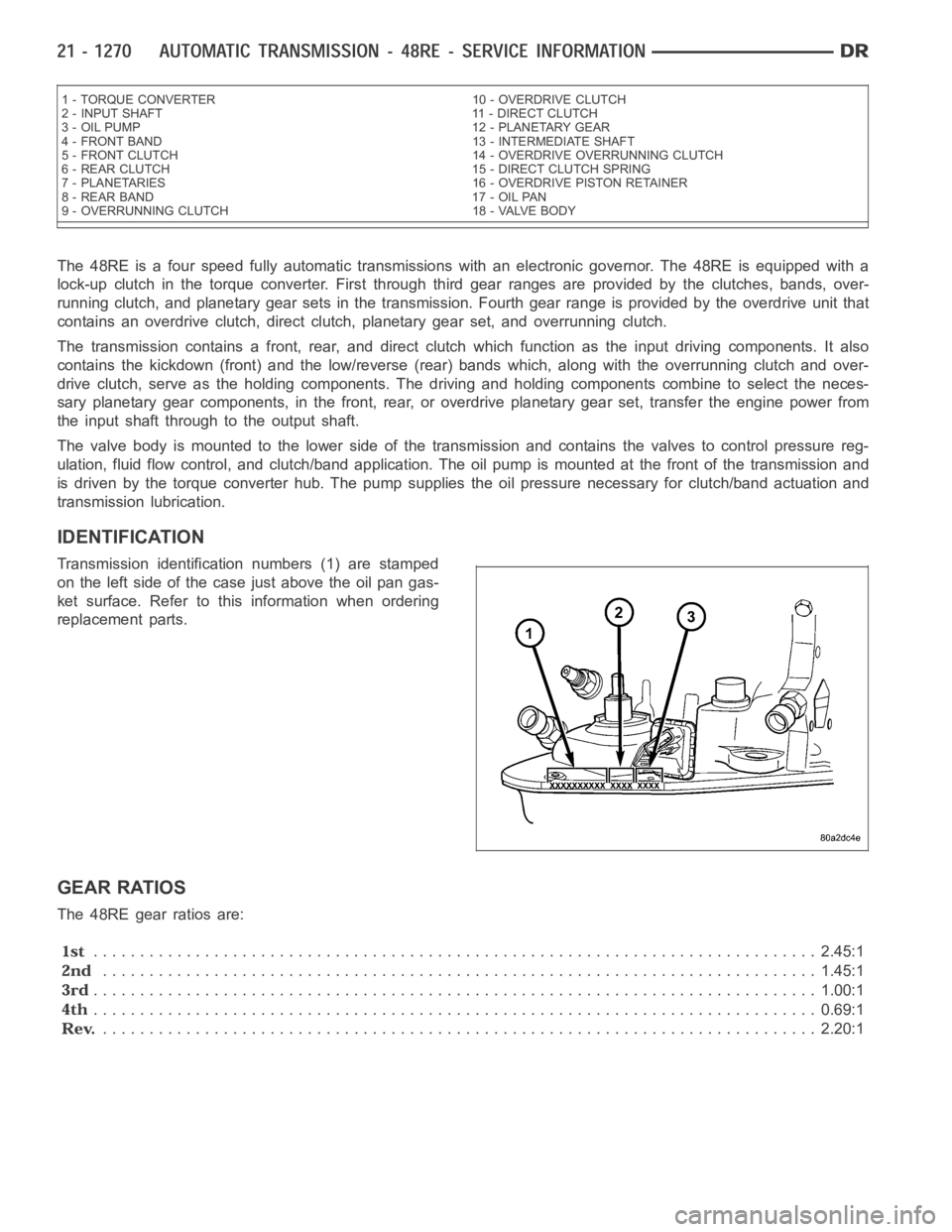
The 48RE is a four speed fully automatic transmissions with an electronic governor. The 48RE is equipped with a
lock-up clutch in the torque converter. First through third gear ranges are provided by the clutches, bands, over-
running clutch, and planetary gear sets in the transmission. Fourth gear range is provided by the overdrive unit that
contains an overdrive clutch, direct clutch, planetary gear set, and overrunning clutch.
The transmission contains a front, rear, and direct clutch which functionas the input driving components. It also
contains the kickdown (front) and the low/reverse (rear) bands which, along with the overrunning clutch and over-
drive clutch, serve as the holding components. The driving and holding components combine to select the neces-
sary planetary gear components, in the front, rear, or overdrive planetary gear set, transfer the engine power from
the input shaft through to the output shaft.
The valve body is mounted to the lower side of the transmission and containsthe valves to control pressure reg-
ulation, fluid flow control, and clutch/band application. The oil pump ismounted at the front of the transmission and
is driven by the torque converter hub. The pump supplies the oil pressure necessary for clutch/band actuation and
transmission lubrication.
IDENTIFICATION
Transmission identification numbers (1) are stamped
on the left side of the case just above the oil pan gas-
ket surface. Refer to this information when ordering
replacement parts.
GEAR RATIOS
The 48RE gear ratios are:
.............................................................................. 2.45:1
............................................................................. 1.45:1
.............................................................................. 1.00:1
.............................................................................. 0.69:1
............................................................................. 2.20:1
1 - TORQUE CONVERTER 10 - OVERDRIVE CLUTCH
2 - INPUT SHAFT 11 - DIRECT CLUTCH
3 - OIL PUMP 12 - PLANETARY GEAR
4 - FRONT BAND 13 - INTERMEDIATE SHAFT
5 - FRONT CLUTCH 14 - OVERDRIVE OVERRUNNING CLUTCH
6 - REAR CLUTCH 15 - DIRECT CLUTCH SPRING
7 - PLANETARIES 16 - OVERDRIVE PISTON RETAINER
8 - REAR BAND 17 - OIL PAN
9 - OVERRUNNING CLUTCH 18 - VALVE BODY
Page 3798 of 5267
pressure to the overdrive clutch during 3-4 upshifts, and when accelerating in fourth gear. The 3-4 accumulator
cushions overdrive clutch engagement to smooth 3-4 upshifts. The accumulator is charged at the same time as
apply pressure acts against the overdrive piston.
DIAGNOSIS AND TESTING
AUTOMATIC TRANSMISSION
Automatic transmission problems can be a result of poor engine performance, incorrect fluid level, incorrect linkage
or cable adjustment, band or hydraulic control pressure adjustments, hydraulic system malfunctions or electrical/
mechanical component malfunctions. Begin diagnosis by checking the easily accessible items such as: fluid level
and condition, linkage adjustments and electrical connections. A road test will determine if further diagnosis is nec-
essary.
PRELIMINARY
Two basic procedures are required. One procedure for vehicles that are drivable and an alternate procedure for
disabled vehicles (will not back up or move forward).
VEHICLE IS DRIVEABLE
1. Check for transmission fault codes using DRBscan tool.
2. Check fluid level and condition.
3. Adjust throttle and gearshift linkage if complaint was based on delayed, erratic, or harsh shifts.
4. Road test and note how transmission upshifts, downshifts, and engages.
5. Perform hydraulic pressure test if shift problems were noted during roadtest.
6. Perform air-pressure test to check clutch-band operation.
VEHICLE IS DISABLED
1. Check fluid level and condition.
2. Check for broken or disconnected gearshift or throttle linkage.
3. Check for cracked, leaking cooler lines, or loose or missing pressure-port plugs.
4. Raise and support vehicle on safety stands, start engine, shift transmission into gear, and note following:
a. If propeller shaft turns but wheels do not, problem is with differentialor axle shafts.
b. If propeller shaft does not turn and transmission is noisy, stop engine.Remove oil pan, and check for debris.
If pan is clear, remove transmission and check for damaged drive plate, converter, oil pump, or input shaft.
c. If propeller shaft does not turn and transmission is not noisy, perform hydraulic-pressure test to determine if
problem is hydraulic or mechanical.
ROAD TESTING
Before road testing, be sure the fluid level and control cable adjustmentshave been checked and adjusted if nec-
essary. Verify that diagnostic trouble codes have been resolved.
Observe engine performance during the road test. A poorly tuned engine will not allow accurate analysis of trans-
mission operation.
Operate the transmission in all gear ranges. Check for shift variations and engine flare which indicates slippage.
Note if shifts are harsh, spongy, delayed, early, or if part throttle downshifts are sensitive.
Slippage indicated by engine flare, usually means clutch, band or overrunning clutch problems. If the condition is
advanced, an overhaul will be necessary to restore normal operation.
A slipping clutch or band can often be determined by comparing which internal units are applied in the various gear
ranges. The Clutch and Band Application chart provides a basis for analyzing road test results.
Clutch and Band Application Chart
Page 3820 of 5267
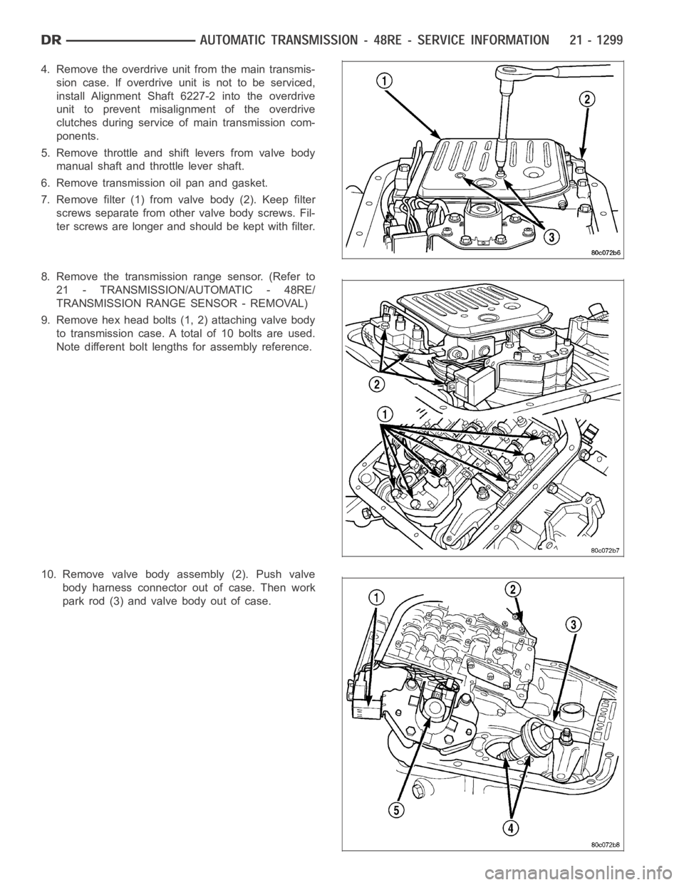
4. Removetheoverdriveunitfromthemaintransmis-
sion case. If overdrive unit is not to be serviced,
install Alignment Shaft 6227-2 into the overdrive
unit to prevent misalignment of the overdrive
clutches during service ofmain transmission com-
ponents.
5. Remove throttle and shift levers from valve body
manual shaft and throttle lever shaft.
6. Remove transmission oil pan and gasket.
7. Remove filter (1) from valve body (2). Keep filter
screws separate from other valve body screws. Fil-
ter screws are longer and should be kept with filter.
8. Remove the transmission range sensor. (Refer to
21 - TRANSMISSION/AUTOMATIC - 48RE/
TRANSMISSION RANGE SENSOR - REMOVAL)
9. Remove hex head bolts (1, 2) attaching valve body
to transmission case. A total of 10 bolts are used.
Note different bolt lengths for assembly reference.
10. Remove valve body assembly (2). Push valve
body harness connector out of case. Then work
park rod (3) and valve body out of case.
Page 3827 of 5267
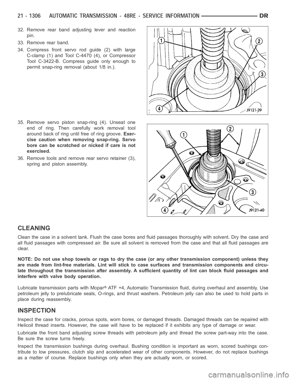
32. Remove rear band adjusting lever and reaction
pin.
33. Remove rear band.
34. Compress front servo rod guide (2) with large
C-clamp (1) and Tool C-4470 (4), or Compressor
Tool C-3422-B. Compress guide only enough to
permit snap-ring removal (about 1/8 in.).
35. Remove servo piston snap-ring (4). Unseat one
end of ring. Then carefully work removal tool
around back of ring until free of ring groove.Exer-
cise caution when removing snap-ring. Servo
bore can be scratched or nicked if care is not
exercised.
36. Remove tools and remove rear servo retainer (3),
spring and piston assembly.
CLEANING
Clean the case in a solvent tank. Flush the case bores and fluid passages thoroughly with solvent. Dry the case and
all fluid passages with compressed air. Be sure all solvent is removed fromthe case and that all fluid passages are
clear.
NOTE: Do not use shop towels or rags to dry the case (or any other transmission component) unless they
aremadefromlint-freematerials.Lintwillsticktocasesurfacesandtransmission components and circu-
late throughout the transmission after assembly. A sufficient quantity of lint can block fluid passages and
interfere with valve body operation.
Lubricate transmission parts with Mopar
ATF +4, Automatic Transmission fluid, during overhaul and assembly. Use
petroleum jelly to prelubricate seals, O-rings, and thrust washers. Petroleumjellycanalsobeusedtoholdpartsin
place during reassembly.
INSPECTION
Inspect the case for cracks, porous spots, worn bores, or damaged threads.Damaged threads can be repaired with
Helicoil thread inserts. However, the case will have to be replaced if it exhibits any type of damage or wear.
Lubricate the front band adjusting screw threads with petroleum jelly andthread the screw part-way into the case.
Be sure the screw turns freely.
Inspect the transmission bushings during overhaul. Bushing condition isimportant as worn, scored bushings con-
tribute to low pressures, clutch slipand accelerated wear of other components. However, do not replace bushings
as a matter of course. Replace bushings only when they are actually worn, orscored.