Page 3840 of 5267
17. For vehicles equipped with a diesel engine, posi-
tion the transmission throttle valve actuator
(TTVA) (1) over the throttle valve shaft (3).
18. Align the D-shaped opening in the bottom of the
TTVA to the throttle valve shaft and install the
TTVA onto the shaft.
19. Install the wiring connector (2) to the TTVA (1).
20. Rotate the TTVA (1) to the transmission case and
install the bolts (2) to hold the TTVA to the trans-
mission.
21. Tighten the bolts to 8.5 Nꞏm (75 in.lbs.).
22. Initialize the TTVA (Refer to 21 - TRANSMIS-
SION/AUTOMATIC - 48RE/THROTTLE VALVE
ACTUATOR - ADJUSTMENTS).
Page 3842 of 5267
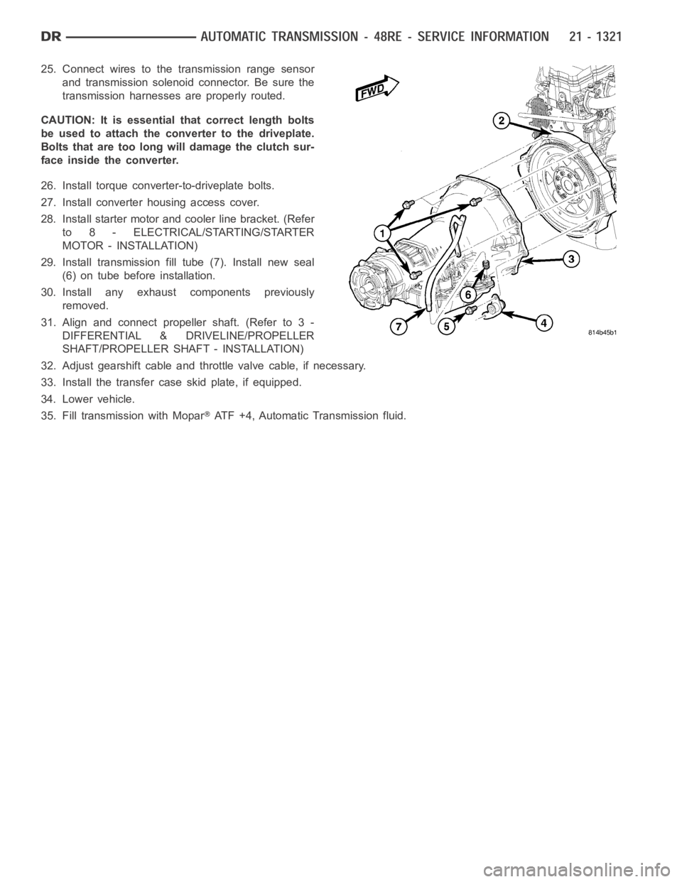
25. Connect wires to the transmission range sensor
and transmission solenoid connector. Be sure the
transmission harnesses are properly routed.
CAUTION: It is essential that correct length bolts
be used to attach the converter to the driveplate.
Bolts that are too long will damage the clutch sur-
face inside the converter.
26. Install torque converter-to-driveplate bolts.
27. Install converter housing access cover.
28. Install starter motor and cooler line bracket. (Refer
to 8 - ELECTRICAL/STARTING/STARTER
MOTOR - INSTALLATION)
29. Install transmission fill tube (7). Install new seal
(6) on tube before installation.
30. Install any exhaust components previously
removed.
31. Align and connect propeller shaft. (Refer to 3 -
DIFFERENTIAL & DRIVELINE/PROPELLER
SHAFT/PROPELLER SHAFT - INSTALLATION)
32. Adjust gearshift cable and throttle valve cable, if necessary.
33. Install the transfer case skid plate, if equipped.
34. Lower vehicle.
35. Fill transmission with Mopar
ATF +4, Automatic Transmission fluid.
Page 3865 of 5267
ADJUSTMENTS
ADJUSTMENT - BANDS
FRONT BAND
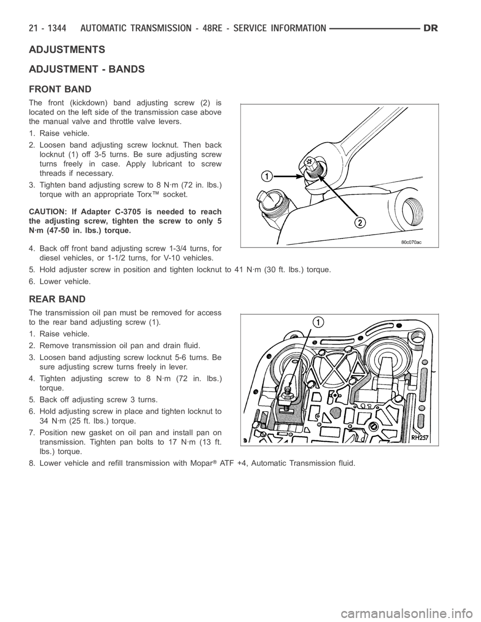
The front (kickdown) band adjusting screw (2) is
located on the left side of the transmission case above
the manual valve and throttle valve levers.
1. Raise vehicle.
2. Loosen band adjusting screw locknut. Then back
locknut (1) off 3-5 turns. Be sure adjusting screw
turns freely in case. Apply lubricant to screw
threads if necessary.
3. Tighten band adjusting screw to 8 Nꞏm (72 in. lbs.)
torque with an appropriate Torx™ socket.
CAUTION: If Adapter C-3705 is needed to reach
the adjusting screw, tighten the screw to only 5
Nꞏm (47-50 in. lbs.) torque.
4. Back off front band adjusting screw 1-3/4 turns, for
diesel vehicles, or 1-1/2 turns, for V-10 vehicles.
5. Hold adjuster screw in position and tighten locknut to 41 Nꞏm (30 ft. lbs.) torque.
6. Lower vehicle.
REAR BAND
The transmission oil pan must be removed for access
to the rear band adjusting screw (1).
1. Raise vehicle.
2. Remove transmission oil pan and drain fluid.
3. Loosen band adjusting screw locknut 5-6 turns. Be
sure adjusting screw turns freely in lever.
4. Tighten adjusting screw to 8 Nꞏm (72 in. lbs.)
torque.
5. Back off adjusting screw 3 turns.
6. Hold adjusting screw in place and tighten locknut to
34 Nꞏm (25 ft. lbs.) torque.
7. Position new gasket on oil pan and install pan on
transmission. Tighten pan bolts to 17 Nꞏm (13 ft.
lbs.) torque.
8. Lower vehicle and refill transmission with Mopar
ATF +4, Automatic Transmission fluid.
Page 3878 of 5267
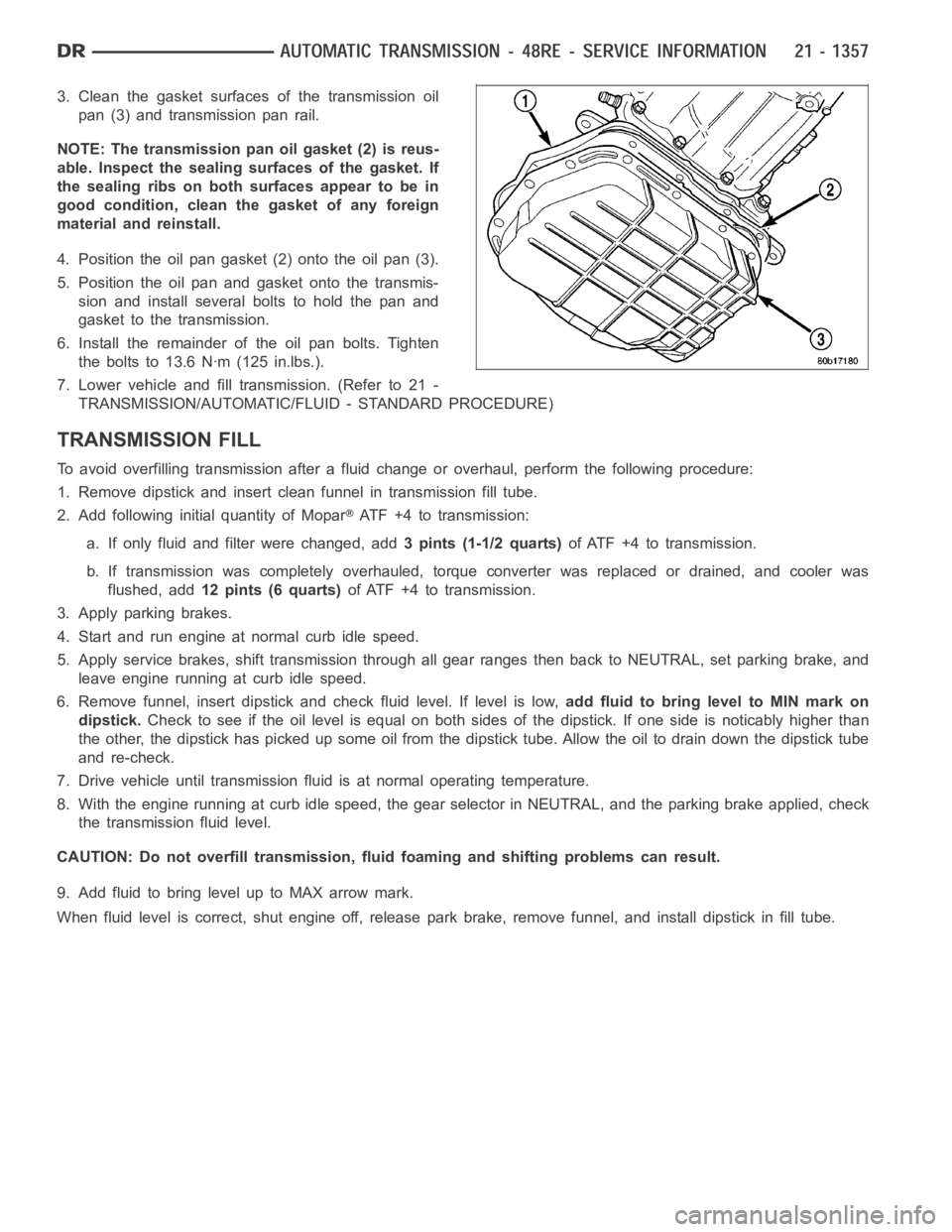
3. Clean the gasket surfaces of the transmission oil
pan (3) and transmission pan rail.
NOTE: The transmission pan oil gasket (2) is reus-
able. Inspect the sealing surfaces of the gasket. If
the sealing ribs on both surfaces appear to be in
good condition, clean the gasket of any foreign
material and reinstall.
4. Position the oil pan gasket (2) onto the oil pan (3).
5. Position the oil pan and gasket onto the transmis-
sion and install several bolts to hold the pan and
gasket to the transmission.
6. Install the remainder of the oil pan bolts. Tighten
the bolts to 13.6 Nꞏm (125 in.lbs.).
7. Lower vehicle and fill transmission. (Refer to 21 -
TRANSMISSION/AUTOMATIC/FLUID - STANDARD PROCEDURE)
TRANSMISSION FILL
To avoid overfilling transmission after a fluid change or overhaul, perform the following procedure:
1. Remove dipstick and insert clean funnel in transmission fill tube.
2. Add following initial quantity of Mopar
ATF+4totransmission:
a. If only fluid and filter were changed, add3 pints (1-1/2 quarts)of ATF +4 to transmission.
b. If transmission was completely overhauled, torque converter was replaced or drained, and cooler was
flushed, add12 pints (6 quarts)of ATF +4 to transmission.
3. Apply parking brakes.
4. Start and run engine at normal curb idle speed.
5. Apply service brakes, shift transmission through all gear ranges then back to NEUTRAL, set parking brake, and
leave engine running at curb idle speed.
6. Remove funnel, insert dipstick andcheck fluid level. If level is low,add fluid to bring level to MIN mark on
dipstick.Check to see if the oil level is equal on both sides of the dipstick. If one side is noticably higher than
the other, the dipstick has picked up some oil from the dipstick tube. Allowthe oil to drain down the dipstick tube
and re-check.
7. Drive vehicle until transmission fluid is at normal operating temperature.
8. With the engine running at curb idle speed, the gear selector in NEUTRAL,and the parking brake applied, check
the transmission fluid level.
CAUTION: Do not overfill transmission, fluid foaming and shifting problems can result.
9. Add fluid to bring level up to MAX arrow mark.
When fluid level is correct, shut engine off, release park brake, remove funnel, and install dipstick in fill tube.
Page 3888 of 5267
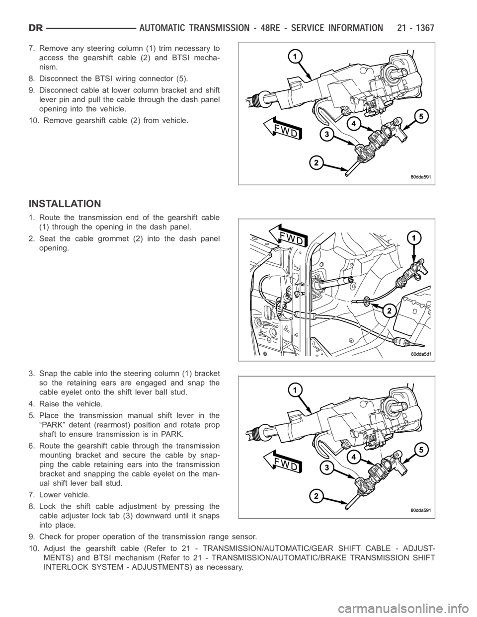
7. Remove any steering column (1) trim necessary to
access the gearshift cable (2) and BTSI mecha-
nism.
8. Disconnect the BTSI wiring connector (5).
9. Disconnect cable at lower column bracket and shift
lever pin and pull the cable through the dash panel
opening into the vehicle.
10. Remove gearshift cable (2) from vehicle.
INSTALLATION
1. Route the transmission end of the gearshift cable
(1) through the opening in the dash panel.
2. Seat the cable grommet (2) into the dash panel
opening.
3. Snap the cable into the steering column (1) bracket
so the retaining ears are engaged and snap the
cable eyelet onto the shift lever ball stud.
4. Raise the vehicle.
5. Place the transmission manual shift lever in the
“PARK” detent (rearmost) position and rotate prop
shaft to ensure transmission is in PARK.
6. Route the gearshift cable through the transmission
mounting bracket and secure the cable by snap-
ping the cable retaining ears into the transmission
bracket and snapping the cable eyelet on the man-
ual shift lever ball stud.
7. Lower vehicle.
8. Lock the shift cable adjustment by pressing the
cable adjuster lock tab (3) downward until it snaps
into place.
9. Check for proper operation of the transmission range sensor.
10. Adjust the gearshift cable (Refer to 21 - TRANSMISSION/AUTOMATIC/GEAR SHIFT CABLE - ADJUST-
MENTS) and BTSI mechanism (Refer to 21 - TRANSMISSION/AUTOMATIC/BRAKE TRANSMISSION SHIFT
INTERLOCK SYSTEM - ADJUSTMENTS) as necessary.
Page 3897 of 5267
BEARING-OUTPUT SHAFT REAR
REMOVAL
1. Remove overdrive unit from the vehicle. (Refer to
21 - TRANSMISSION/AUTOMATIC/OVERDRIVE -
REMOVAL)
2. Remove overdrive geartrain from housing.
3. Remove snap-ring (3) holding output shaft rear
bearing (1) into overdrive housing (2).
4. Using a suitable driver inserted through the rear
end of housing, drive bearing from housing.
INSTALLATION
1. Place replacement bearing (1) in position in hous-
ing (2).
2. Using a suitable driver, drive bearing (1) into hous-
ing (2) until the snap-ring groove is visible.
3. Install snap-ring (3) to hold bearing into housing.
4. Install overdrive geartrain into housing.
5. Install overdrive unit in vehicle.
Page 3911 of 5267
ASSEMBLY
GEARTRAIN AND DIRECT CLUTCH
1. Soak direct clutch and overdrive clutch discs in
Mopar
ATF +4, Automatic Transmission fluid.
Allow discs to soak for 10-20 minutes.
2. Install annulus gear (3) on output shaft, if removed.
Then install annulus gear retaining snap-ring (1).
3. Align and install clutch drum (3) on annulus gear
(1). Be sure drum is engaged in annulus gear lugs.
4. Install clutch drum outer retaining ring (2).
5. Slide clutch drum (3) forward and install inner
retaining ring (2).
Page 3942 of 5267
SERVO-REAR
DESCRIPTION
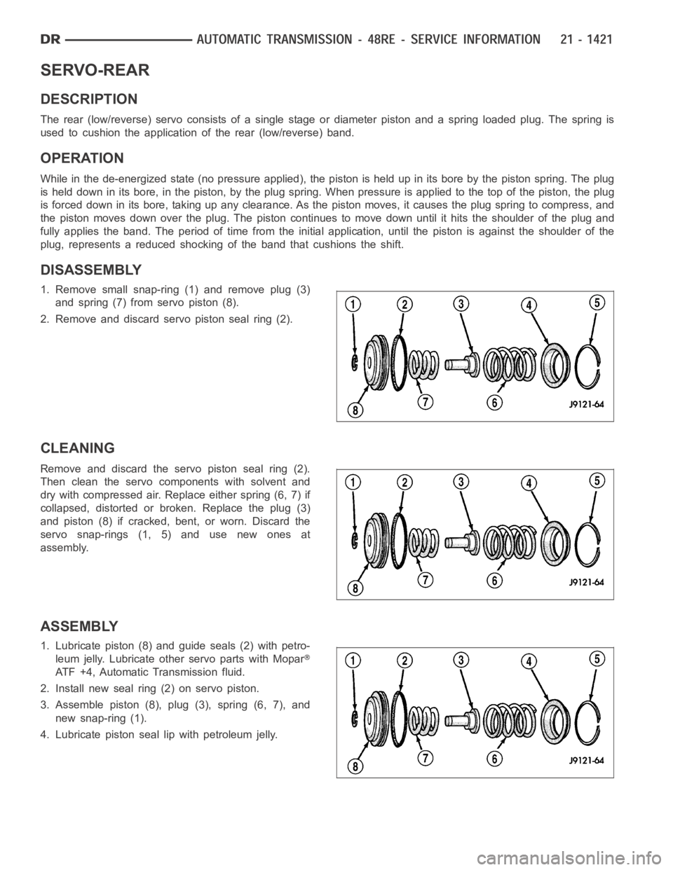
The rear (low/reverse) servo consists of a single stage or diameter pistonand a spring loaded plug. The spring is
used to cushion the application of the rear (low/reverse) band.
OPERATION
While in the de-energized state (no pressure applied), the piston is held up in its bore by the piston spring. The plug
is held down in its bore, in the piston, by the plug spring. When pressure is applied to the top of the piston, the plug
is forced down in its bore, taking up any clearance. As the piston moves, it causes the plug spring to compress, and
the piston moves down over the plug. The piston continues to move down untilit hits the shoulder of the plug and
fully applies the band. The period of time from the initial application, until the piston is against the shoulder of the
plug, represents a reduced shocking of the band that cushions the shift.
DISASSEMBLY
1. Remove small snap-ring (1) and remove plug (3)
and spring (7) from servo piston (8).
2. Remove and discard servo piston seal ring (2).
CLEANING
Remove and discard the servo piston seal ring (2).
Then clean the servo components with solvent and
dry with compressed air. Replace either spring (6, 7) if
collapsed, distorted or broken. Replace the plug (3)
and piston (8) if cracked, bent, or worn. Discard the
servo snap-rings (1, 5) and use new ones at
assembly.
ASSEMBLY
1. Lubricate piston (8) and guide seals (2) with petro-
leum jelly. Lubricate other servo parts with Mopar
ATF +4, Automatic Transmission fluid.
2. Install new seal ring (2) on servo piston.
3. Assemble piston (8), plug (3), spring (6, 7), and
new snap-ring (1).
4. Lubricate piston seal lip with petroleum jelly.