Page 1326 of 5267

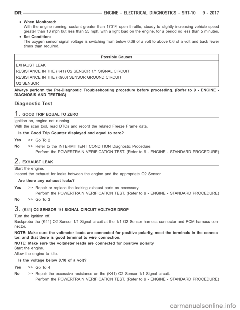
When Monitored:
With the engine running, coolant greater than 170°F, open throttle, steady to slightly increasing vehicle speed
greater than 18 mph but less than 55 mph, with a light load on the engine, for aperiod no less than 5 minutes.
Set Condition:
The oxygen sensor signal voltage is switching from below 0.39 of a volt to above 0.6 of a volt and back fewer
times than required.
Possible Causes
EXHAUST LEAK
RESISTANCE IN THE (K41) O2 SENSOR 1/1 SIGNAL CIRCUIT
RESISTANCE IN THE (K900) SENSOR GROUND CIRCUIT
O2 SENSOR
Always perform the Pre-Diagnostic Troubleshooting procedure before proceeding. (Refer to 9 - ENGINE -
DIAGNOSIS AND TESTING)
Diagnostic Test
1.GOOD TRIP EQUAL TO ZERO
Ignition on, engine not running.
With the scan tool, read DTCs and record the related Freeze Frame data.
Is the Good Trip Counter displayed and equal to zero?
Ye s>>
Go To 2
No>>
Refer to the INTERMITTENT CONDITION Diagnostic Procedure.
Perform the POWERTRAIN VERIFICATION TEST. (Refer to 9 - ENGINE - STANDARD PROCEDURE)
2.EXHAUST LEAK
Start the engine.
Inspect the exhaust for leaks between the engine and the appropriate O2 Sensor.
Are there any exhaust leaks?
Ye s>>
Repair or replace the leaking exhaust parts as necessary.
Perform the POWERTRAIN VERIFICATION TEST. (Refer to 9 - ENGINE - STANDARD PROCEDURE)
No>>
Go To 3
3.(K41) O2 SENSOR 1/1 SIGNAL CIRCUIT VOLTAGE DROP
Turn the ignition off.
Backprobe the (K41) O2 Sensor 1/1 Signal circuit at the 1/1 O2 Sensor harness connector and PCM harness con-
nector.
NOTE: Make sure the voltmeter leads are connected for positive polarity, meet the terminals in the connec-
tor, and that there is good terminal to wire connection.
NOTE: Make sure the voltmeter leads are connected for positive polarity
Start the engine.
Allow the engine to idle.
Is the voltage below 0.10 of a volt?
Ye s>>
Go To 4
No>>
Repair the excessive resistance on the (K41) O2 Sensor 1/1 Signal circuit.
Perform the POWERTRAIN VERIFICATION TEST. (Refer to 9 - ENGINE - STANDARD PROCEDURE)
Page 1327 of 5267
4.(K900) SENSOR GROUND CIRCUIT VOLTAGE DROP
Turn the ignition off.
Backprobe the (K900) Sensor ground circuit at the O2 Sensor harness connector and PCM harness connector.
NOTE: Make sure the voltmeter leads are connected for positive polarity, meet the terminals in the connec-
tor, and that there is good terminal to wire connection.
NOTE: Make sure the voltmeter leads are connected for positive polarity
Start the engine.
Allow the engine to idle.
Is the voltage below 0.10 of a volt?
Ye s>>
Go To 5
No>>
Repair the excessive resistance in the (K900) Sensor ground circuit.
Perform the POWERTRAIN VERIFICATION TEST. (Refer to 9 - ENGINE - STANDARD PROCEDURE)
5.O2 SENSOR
Turn the ignition off.
If there are no possible causes remaining, view repair.
Repair
Replace the O2 Sensor
Perform the POWERTRAIN VERIFICATION TEST. (Refer to 9 - ENGINE - STANDARD PROCEDURE)
Page 1328 of 5267
P1196-O2 SENSOR 2/1 SLOW DURING CATALYST MONITOR
For a complete wiring diagramRefer to Section 8W.
Page 1329 of 5267

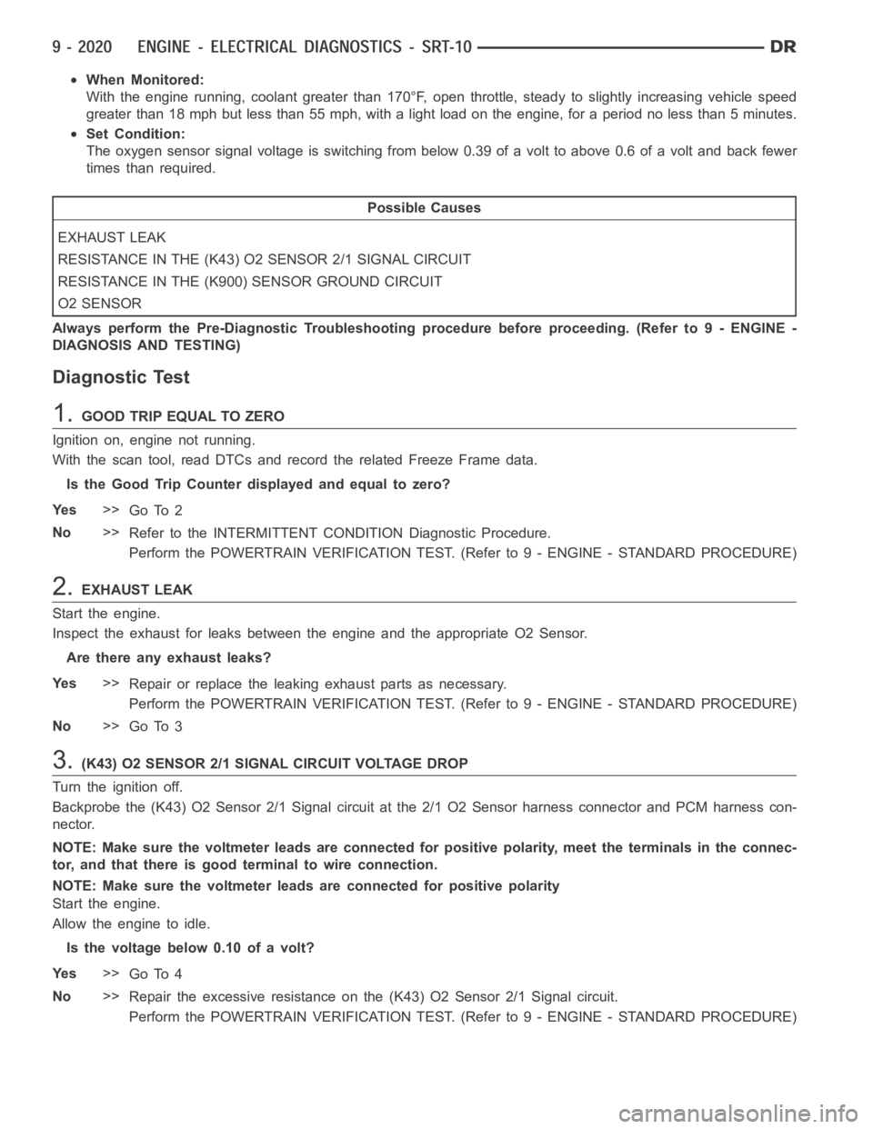
When Monitored:
With the engine running, coolant greater than 170°F, open throttle, steady to slightly increasing vehicle speed
greater than 18 mph but less than 55 mph, with a light load on the engine, for aperiod no less than 5 minutes.
Set Condition:
The oxygen sensor signal voltage is switching from below 0.39 of a volt to above 0.6 of a volt and back fewer
times than required.
Possible Causes
EXHAUST LEAK
RESISTANCE IN THE (K43) O2 SENSOR 2/1 SIGNAL CIRCUIT
RESISTANCE IN THE (K900) SENSOR GROUND CIRCUIT
O2 SENSOR
Always perform the Pre-Diagnostic Troubleshooting procedure before proceeding. (Refer to 9 - ENGINE -
DIAGNOSIS AND TESTING)
Diagnostic Test
1.GOOD TRIP EQUAL TO ZERO
Ignition on, engine not running.
With the scan tool, read DTCs and record the related Freeze Frame data.
Is the Good Trip Counter displayed and equal to zero?
Ye s>>
Go To 2
No>>
Refer to the INTERMITTENT CONDITION Diagnostic Procedure.
Perform the POWERTRAIN VERIFICATION TEST. (Refer to 9 - ENGINE - STANDARD PROCEDURE)
2.EXHAUST LEAK
Start the engine.
Inspect the exhaust for leaks between the engine and the appropriate O2 Sensor.
Are there any exhaust leaks?
Ye s>>
Repair or replace the leaking exhaust parts as necessary.
Perform the POWERTRAIN VERIFICATION TEST. (Refer to 9 - ENGINE - STANDARD PROCEDURE)
No>>
Go To 3
3.(K43) O2 SENSOR 2/1 SIGNAL CIRCUIT VOLTAGE DROP
Turn the ignition off.
Backprobe the (K43) O2 Sensor 2/1 Signal circuit at the 2/1 O2 Sensor harness connector and PCM harness con-
nector.
NOTE: Make sure the voltmeter leads are connected for positive polarity, meet the terminals in the connec-
tor, and that there is good terminal to wire connection.
NOTE: Make sure the voltmeter leads are connected for positive polarity
Start the engine.
Allow the engine to idle.
Is the voltage below 0.10 of a volt?
Ye s>>
Go To 4
No>>
Repair the excessive resistance on the (K43) O2 Sensor 2/1 Signal circuit.
Perform the POWERTRAIN VERIFICATION TEST. (Refer to 9 - ENGINE - STANDARD PROCEDURE)
Page 1330 of 5267
4.(K900) SENSOR GROUND CIRCUIT VOLTAGE DROP
Turn the ignition off.
Backprobe the (K900) Sensor ground circuit at the 2/1 O2 Sensor harness connector and PCM harness connector.
NOTE: Make sure the voltmeter leads are connected for positive polarity, meet the terminals in the connec-
tor, and that there is good terminal to wire connection.
NOTE: Make sure the voltmeter leads are connected for positive polarity
Start the engine.
Allow the engine to idle.
Is the voltage below 0.10 of a volt?
Ye s>>
Go To 5
No>>
Repair the excessive resistance in the (K900) Sensor ground circuit.
Perform the POWERTRAIN VERIFICATION TEST. (Refer to 9 - ENGINE - STANDARD PROCEDURE)
5.O2 SENSOR
Turn the ignition off.
If there are no possible causes remaining, view repair.
Repair
Replace the O2 Sensor
Perform the POWERTRAIN VERIFICATION TEST. (Refer to 9 - ENGINE - STANDARD PROCEDURE)
Page 1387 of 5267

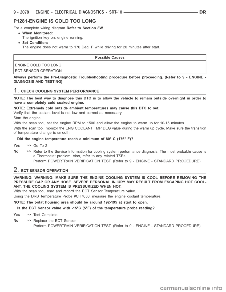
P1281-ENGINE IS COLD TOO LONG
For a complete wiring diagramRefer to Section 8W.
When Monitored:
The ignition key on, engine running.
Set Condition:
The engine does not warm to 176 Deg. F while driving for 20 minutes after start.
Possible Causes
ENGINE COLD TOO LONG
ECT SENSOR OPERATION
Always perform the Pre-Diagnostic Troubleshooting procedure before proceeding. (Refer to 9 - ENGINE -
DIAGNOSIS AND TESTING)
1.CHECK COOLING SYSTEM PERFORMANCE
NOTE: The best way to diagnose this DTC is to allow the vehicle to remain outside overnight in order to
have a completely cold soaked engine.
NOTE: Extremely cold outside ambient temperatures may cause this DTC to set.
Verify that the coolant level is not low and correct as necessary.
Start the engine.
With the scan tool, set the engine RPM to 1500 and allow the engine to warm up for 10-15 minutes.
With the scan tool, monitor the ENG COOLANT TMP DEG value during the warm up cycle. Make sure the transition
of temperature change is smooth.
Did the engine temperature reach a minimum of 80° C (176° F)?
Ye s>>
Go To 2
No>>
Refer to the Service Information for cooling system performance diagnosis. The most probable cause is
a Thermostat problem. Also, refer to any related TSBs.
Perform POWERTRAIN VERIFICATION TEST. (Refer to 9 - ENGINE - STANDARD PROCEDURE)
2.ECT SENSOR OPERATION
WARNING: WARNING: MAKE SURE THE ENGINE COOLING SYSTEM IS COOL BEFORE REMOVING THE
PRESSURE CAP OR ANY HOSE. SEVERE PERSONAL INJURY MAY RESULT FROM ESCAPING HOT COOL-
ANT. THE COOLING SYSTEM IS PRESSURIZED WHEN HOT.
With the scan tool, read and record the ECT Sensor Temperature value.
Using the DRB Temperature Probe #CH7050, measure the engine coolant temperature.
NOTE: The t-stat housing area should be around 192-195 at start to open.
Is the ECT Sensor value with -15°C (5°F) of the temperature probe reading?
Ye s>>
Te s t C o m p l e t e .
No>>
Replace the ECT Sensor.
Perform POWERTRAIN VERIFICATION TEST. (Refer to 9 - ENGINE - STANDARD PROCEDURE)
Page 1392 of 5267

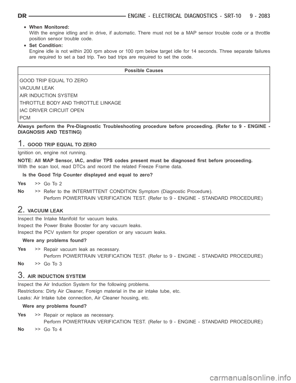
When Monitored:
With the engine idling and in drive, if automatic. There must not be a MAP sensor trouble code or a throttle
position sensor trouble code.
Set Condition:
Engine idle is not within 200 rpm above or 100 rpm below target idle for 14 seconds. Three separate failures
are required to set a bad trip. Two bad trips are required to set the code.
Possible Causes
GOOD TRIP EQUAL TO ZERO
VACUUM LEAK
AIR INDUCTION SYSTEM
THROTTLE BODY AND THROTTLE LINKAGE
IAC DRIVER CIRCUIT OPEN
PCM
Always perform the Pre-Diagnostic Troubleshooting procedure before proceeding. (Refer to 9 - ENGINE -
DIAGNOSIS AND TESTING)
1.GOOD TRIP EQUAL TO ZERO
Ignition on, engine not running.
NOTE: All MAP Sensor, IAC, and/or TPS codes present must be diagnosed firstbefore proceeding.
With the scan tool, read DTCs and record the related Freeze Frame data.
Is the Good Trip Counter displayed and equal to zero?
Ye s>>
Go To 2
No>>
Refer to the INTERMITTENT CONDITIONSymptom (Diagnostic Procedure).
Perform POWERTRAIN VERIFICATION TEST. (Refer to 9 - ENGINE - STANDARD PROCEDURE)
2.VACUUM LEAK
Inspect the Intake Manifold for vacuum leaks.
Inspect the Power Brake Booster for any vacuum leaks.
Inspect the PCV system for proper operation or any vacuum leaks.
Were any problems found?
Ye s>>
Repair vacuum leak as necessary.
Perform POWERTRAIN VERIFICATION TEST. (Refer to 9 - ENGINE - STANDARD PROCEDURE)
No>>
Go To 3
3.AIR INDUCTION SYSTEM
Inspect the Air Induction System for the following problems.
Restrictions: Dirty Air Cleaner, Foreign material in the air intake tube,etc.
Leaks: Air Intake tube connection, Air Cleaner housing, etc.
Were any problems found?
Ye s>>
Repair or replace as necessary.
Perform POWERTRAIN VERIFICATION TEST. (Refer to 9 - ENGINE - STANDARD PROCEDURE)
No>>
Go To 4
Page 1394 of 5267
P1296-NO 5-VOLTS TO MAP SENSOR
For a complete wiring diagramRefer to Section 8W.