2006 DODGE RAM SRT-10 sensor
[x] Cancel search: sensorPage 1240 of 5267
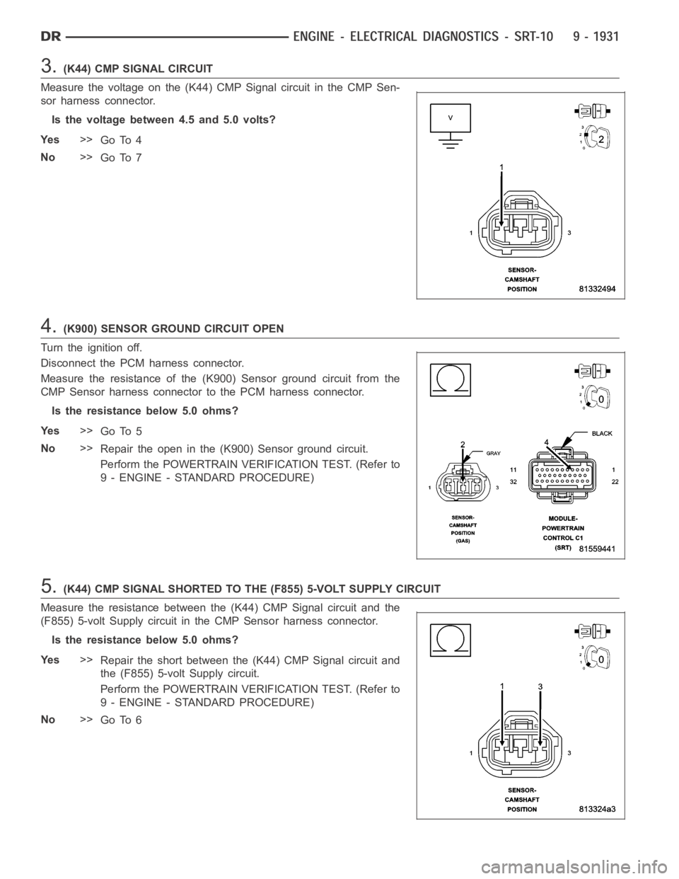
3.(K44) CMP SIGNAL CIRCUIT
Measure the voltage on the (K44) CMP Signal circuit in the CMP Sen-
sor harness connector.
Is the voltage between 4.5 and 5.0 volts?
Ye s>>
Go To 4
No>>
Go To 7
4.(K900) SENSOR GROUND CIRCUIT OPEN
Turn the ignition off.
Disconnect the PCM harness connector.
Measure the resistance of the (K900) Sensor ground circuit from the
CMP Sensor harness connector to the PCM harness connector.
Is the resistance below 5.0 ohms?
Ye s>>
Go To 5
No>>
Repair the open in the (K900) Sensor ground circuit.
Perform the POWERTRAIN VERIFICATION TEST. (Refer to
9 - ENGINE - STANDARD PROCEDURE)
5.(K44) CMP SIGNAL SHORTED TO THE (F855) 5-VOLT SUPPLY CIRCUIT
Measure the resistance between the (K44) CMP Signal circuit and the
(F855) 5-volt Supply circuit in the CMP Sensor harness connector.
Is the resistance below 5.0 ohms?
Ye s>>
Repair the short between the (K44) CMP Signal circuit and
the (F855) 5-volt Supply circuit.
Perform the POWERTRAIN VERIFICATION TEST. (Refer to
9 - ENGINE - STANDARD PROCEDURE)
No>>
Go To 6
Page 1241 of 5267
6.CAMSHAFT POSITION SENSOR
NOTE: Inspect the Camshaft sprocket for damage per the Service Information. If a problem is found repair
as necessary.
If there are no possible causes remaining, view repair.
Repair
Replace the Camshaft Position Sensor.
Perform the POWERTRAIN VERIFICATION TEST. (Refer to 9 - ENGINE - STANDARD PROCEDURE)
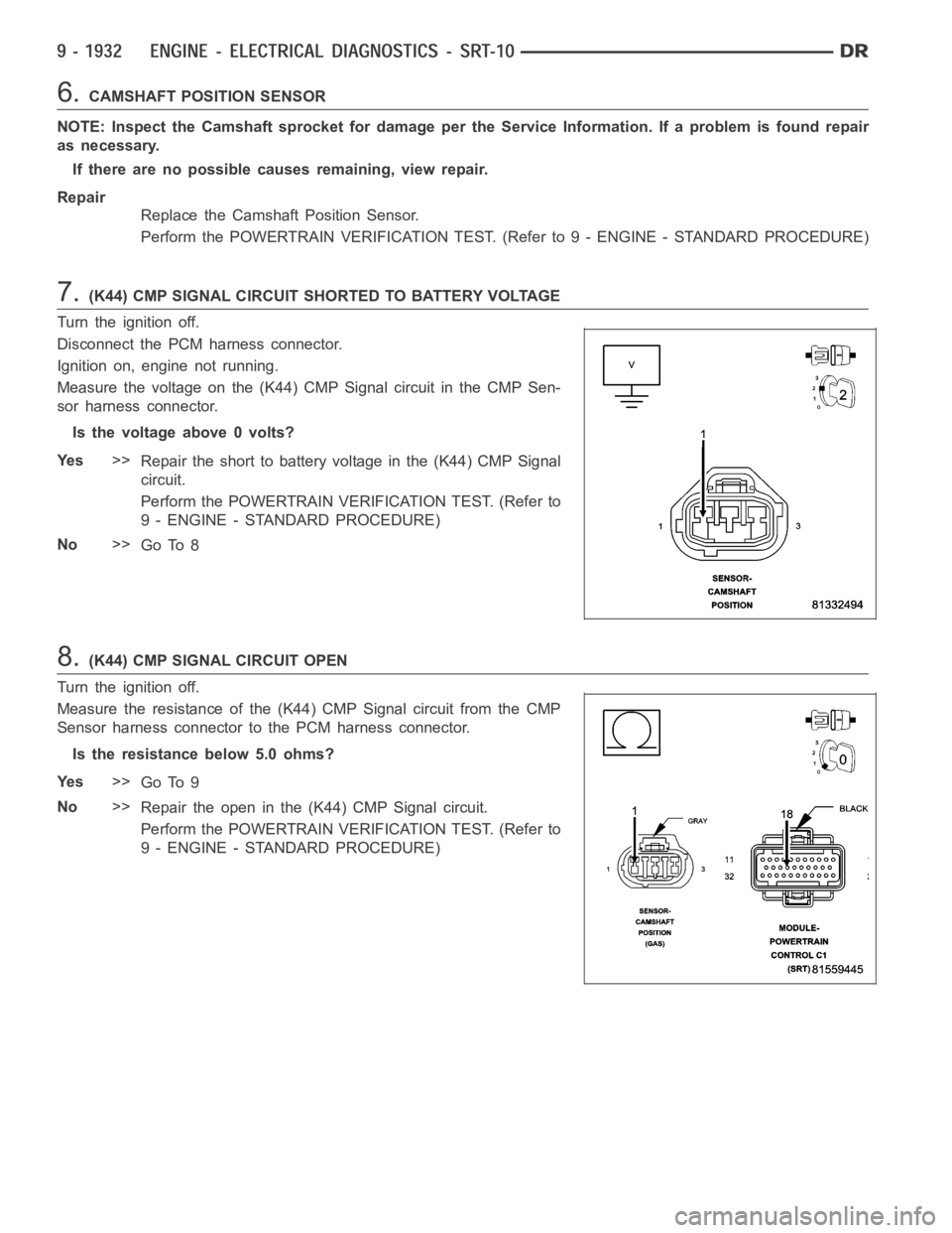
7.(K44) CMP SIGNAL CIRCUIT SHORTED TO BATTERY VOLTAGE
Turn the ignition off.
Disconnect the PCM harness connector.
Ignition on, engine not running.
Measure the voltage on the (K44) CMP Signal circuit in the CMP Sen-
sor harness connector.
Is the voltage above 0 volts?
Ye s>>
Repair the short to battery voltage in the (K44) CMP Signal
circuit.
Perform the POWERTRAIN VERIFICATION TEST. (Refer to
9 - ENGINE - STANDARD PROCEDURE)
No>>
Go To 8
8.(K44) CMP SIGNAL CIRCUIT OPEN
Turn the ignition off.
Measure the resistance of the (K44) CMP Signal circuit from the CMP
Sensor harness connector to the PCM harness connector.
Is the resistance below 5.0 ohms?
Ye s>>
Go To 9
No>>
Repair the open in the (K44) CMP Signal circuit.
Perform the POWERTRAIN VERIFICATION TEST. (Refer to
9 - ENGINE - STANDARD PROCEDURE)
Page 1242 of 5267
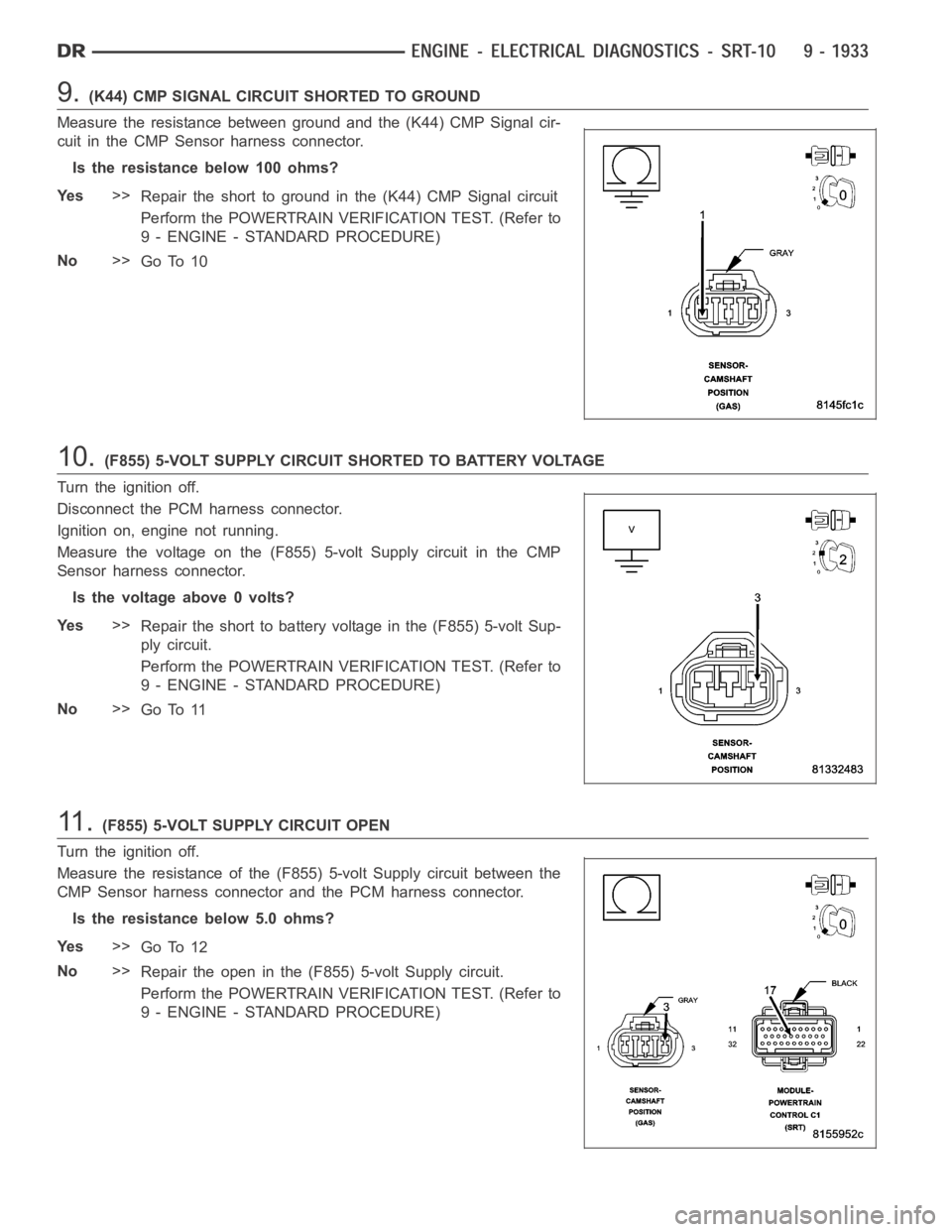
9.(K44) CMP SIGNAL CIRCUIT SHORTED TO GROUND
Measure the resistance between ground and the (K44) CMP Signal cir-
cuit in the CMP Sensor harness connector.
Istheresistancebelow100ohms?
Ye s>>
Repair the short to ground in the (K44) CMP Signal circuit
Perform the POWERTRAIN VERIFICATION TEST. (Refer to
9 - ENGINE - STANDARD PROCEDURE)
No>>
Go To 10
10.(F855) 5-VOLT SUPPLY CIRCUIT SHORTED TO BATTERY VOLTAGE
Turn the ignition off.
Disconnect the PCM harness connector.
Ignition on, engine not running.
Measure the voltage on the (F855) 5-volt Supply circuit in the CMP
Sensor harness connector.
Is the voltage above 0 volts?
Ye s>>
Repair the short to battery voltage in the (F855) 5-volt Sup-
ply circuit.
Perform the POWERTRAIN VERIFICATION TEST. (Refer to
9 - ENGINE - STANDARD PROCEDURE)
No>>
Go To 11
11 .(F855) 5-VOLT SUPPLY CIRCUIT OPEN
Turn the ignition off.
Measure the resistance of the (F855) 5-volt Supply circuit between the
CMP Sensor harness connector and the PCM harness connector.
Is the resistance below 5.0 ohms?
Ye s>>
Go To 12
No>>
Repair the open in the (F855) 5-volt Supply circuit.
Perform the POWERTRAIN VERIFICATION TEST. (Refer to
9 - ENGINE - STANDARD PROCEDURE)
Page 1243 of 5267
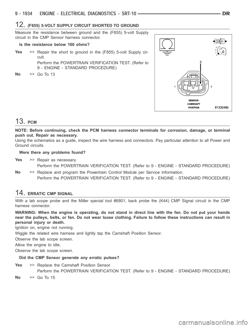
12.(F855) 5-VOLT SUPPLY CIRCUIT SHORTED TO GROUND
Measure the resistance between ground and the (F855) 5-volt Supply
circuit in the CMP Sensor harness connector.
Istheresistancebelow100ohms?
Ye s>>
Repair the short to ground in the (F855) 5-volt Supply cir-
cuit.
Perform the POWERTRAIN VERIFICATION TEST. (Refer to
9 - ENGINE - STANDARD PROCEDURE)
No>>
Go To 13
13.PCM
NOTE: Before continuing, check the PCM harness connector terminals for corrosion, damage, or terminal
push out. Repair as necessary.
Using the schematics as a guide, inspect the wire harness and connectors. Pay particular attention to all Power and
Ground circuits.
Were there any problems found?
Ye s>>
Repair as necessary.
Perform the POWERTRAIN VERIFICATION TEST. (Refer to 9 - ENGINE - STANDARD PROCEDURE)
No>>
Replace and program the Powertrain Control Module per Service Information.
Perform the POWERTRAIN VERIFICATION TEST. (Refer to 9 - ENGINE - STANDARD PROCEDURE)
14.ERRATIC CMP SIGNAL
With a lab scope probe and the Miller special tool #6801, back probe the (K44) CMP Signal circuit in the CMP
harness connector.
WARNING: When the engine is operating, do not stand in direct line with the fan. Do not put your hands
near the pulleys, belts, or fan. Do notwear loose clothing. Failure to follow these instructions can result in
personal injury or death.
Ignition on, engine not running.
Wiggle the related wire harness and lightly tap the Camshaft Position Sensor.
Observe the lab scope screen.
Allow the engine to idle.
Observe the lab scope screen.
Did the CMP Sensor generate any erratic pulses?
Ye s>>
Replace the Camshaft Position Sensor.
Perform the POWERTRAIN VERIFICATION TEST. (Refer to 9 - ENGINE - STANDARD PROCEDURE)
No>>
Go To 15
Page 1244 of 5267
15.ERRATIC CKP SIGNAL
Turn the ignition off.
With a lab scope probe and the Miller special tool #6801, backprobe the (K24) CKP Signal circuit in the CKP har-
ness connector.
WARNING: When the engine is operating, do not stand in direct line with the fan. Do not put your hands
near the pulleys, belts, or fan. Do notwear loose clothing. Failure to follow these instructions can result in
personal injury or death.
Ignition on, engine not running.
Wiggle the related wire harness and lightly tap on the Crankshaft PositionSensor.
Observe the lab scope screen.
Allow the engine to idle.
Observe the lab scope screen.
Did the CKP Sensor generate any erratic pulses?
Ye s>>
Replace the Crankshaft Position Sensor.
Perform the POWERTRAIN VERIFICATION TEST. (Refer to 9 - ENGINE - STANDARD PROCEDURE)
No>>
Test complete, the conditions that set this DTC are not present at this time
Page 1262 of 5267
Theory of Operation
The upstream O2 sensor is used to detect the amount of oxygen in the exhaust gas before the gas enters the
catalytic converter. During the catalyst/O2 monitor test, the response rate (cycles/second) of the upstream O2 sen-
sor determines the sensor’s ability to achieve the tailpipe emissions limits. The response rate of the downstream O2
sensor relative to the upstream O2 sensor response rate measures the catalyst’s ability to store oxygen and is used
to infer the catalyst’s ability to achieve the tailpipe emissions limits.
When Monitored:
After engine warm up to 70°C (158°F), 180 seconds of open throttle operation, at a speed greater than 18 mph
and less than 55 mph, with the engine at 1200-1700 rpm and MAP vacuum between15.0 and 21.0 inches of
mercury (Hg).
Set Condition:
As catalyst efficiency deteriorates, the switch rate of the downstream O2sensor approaches that of the
upstream O2 sensor. If at any point during the test the switch ratio reachesa predetermined value a counter
is incremented by one. Three good trips to turn off the MIL.
Possible Causes
EXHAUST LEAK
ENGINE MECHANICAL
AGING O2 SENSOR
CATALYTIC CONVERTER
Always perform the Pre-Diagnostic Troubleshooting procedure before proceeding. (Refer to 9 - ENGINE -
DIAGNOSIS AND TESTING).
Diagnostic Test
1.ACTIVE DTC
NOTE: A new rear O2 Sensor along with an aging front O2 Sensor may cause the DTCtoset.Reviewthe
repair history of the vehicle before continuing.
NOTE: If an O2 Sensor DTC set along with the Catalytic Converter EfficiencyDTC diagnose the O2 Sensor
DTC(s) before continuing.
NOTE: Check for contaminants that may have damaged the O2 Sensor and Catalytic Converter: contami-
nated fuel, unapproved silicone, oil and coolant, repair necessary.
Ignition on, engine not running.
With a scan tool, read DTCs.
Is the DTC active at this time?
Ye s>>
Go To 2
No>>
Refer to the INTERMITTENT CONDITION Diagnostic Procedure.
Perform the POWERTRAIN VERIFICATION TEST. (Refer to 9 - ENGINE - STANDARD PROCEDURE)
Page 1263 of 5267
2.VISUALLY INSPECT CATALYTIC CONVERTER
Inspect the Catalytic Converter for the following damage.
Damaged Catalytic Converter, dents or holes.
Severe discoloration caused by overheating the Catalytic Converter.
Catalytic Converter broken internally.
Leaking Catalytic Converter.
Were any problems found?
Ye s>>
Replace the Catalytic Converter. Repair the condition that may have caused the failure.
Perform the POWERTRAIN VERIFICATION TEST. (Refer to 9 - ENGINE - STANDARD PROCEDURE)
No>>
Go To 3
3.EXHAUST LEAK
Start the engine.
Inspect the exhaust for leaks between the engine and the 1/1 O2 Sensor.
Inspect the exhaust for leaks between the engine and the 1/2 O2 Sensor.
Are there any exhaust leaks?
Ye s>>
Repair or replace the leaking exhaust parts as necessary.
Perform the POWERTRAIN VERIFICATION TEST. (Refer to 9 - ENGINE - STANDARD PROCEDURE)
No>>
Go To 4
4.ENGINE MECHANICAL
Check the exhaust for excessive smoke caused by an internal problem in the engine.
Is an engine mechanical condition present?
Ye s>>
Repair the engine mechanical condition as necessary.
Perform the POWERTRAIN VERIFICATION TEST. (Refer to 9 - ENGINE - STANDARD PROCEDURE)
No>>
Go To 5
5.AGING O2 SENSOR
A new rear O2 Sensor along with an aging front O2 Sensor may cause the DTC to set.
Review the vehicles repair history.
Has the rear O2 Sensor been replaced without replacing the front O2 Sensor?
Ye s>>
Replace the Front O2 Sensor as necessary.
Perform the POWERTRAIN VERIFICATION TEST. (Refer to 9 - ENGINE - STANDARD PROCEDURE)
No>>
Go To 6
6.CATALYTIC CONVERTER
If there are no possible cause remaining, view repair.
Repair
Replace the Catalytic Converter.
Perform the POWERTRAIN VERIFICATION TEST. (Refer to 9 - ENGINE - STANDARD PROCEDURE)
Page 1265 of 5267

Theory of Operation
The upstream O2 sensor is used to detect the amount of oxygen in the exhaust gas before the gas enters the
catalytic converter. During the catalyst/O2 monitor test, the response rate (cycles/second) of the upstream O2 sen-
sor determines the sensor’s ability to achieve the tailpipe emissions limits. The response rate of the downstream O2
sensor relative to the upstream O2 sensor response rate measures the catalyst’s ability to store oxygen and is used
to infer the catalyst’s ability to achieve the tailpipe emissions limits.
When Monitored:
After engine warm up to 147 deg. F, 180 seconds of open throttle operation, at a speed greater than 20 mph,
with the engine at 1200-1700 rpm and MAP vacuum between 15.0 and 21.0 inchesof mercury (Hg).
Set Condition:
As catalyst efficiency deteriorates, the switch rate of the downstream O2sensor approaches that of the
upstream O2 sensor. If at any point during the test the switch ratio reachesa predetermined value a counter
is incremented by one. Three good trips to turn off the MIL.
Possible Causes
EXHAUST LEAK
ENGINE MECHANICAL
AGING O2 SENSOR
CATALYTIC CONVERTER
Always perform the Pre-Diagnostic Troubleshooting procedure before proceeding. (Refer to 9 - ENGINE -
DIAGNOSIS AND TESTING).
Diagnostic Test
1.ACTIVE DTC
NOTE: A new rear O2 Sensor along with an aging front O2 Sensor may cause the DTCtoset.Reviewthe
repair history of the vehicle before continuing.
NOTE: If an O2 Sensor DTC set along with the Catalytic Converter EfficiencyDTC diagnose the O2 Sensor
DTC(s) before continuing.
NOTE: Check for contaminants that may have damaged the O2 Sensor and Catalytic Converter: contami-
nated fuel, unapproved silicone, oil and coolant, repair necessary.
Ignition on, engine not running.
With a scan tool, read DTCs.
Is the DTC active at this time?
Ye s>>
Go To 2
No>>
Refer to the INTERMITTENT CONDITION Diagnostic Procedure.
Perform the POWERTRAIN VERIFICATION TEST. (Refer to 9 - ENGINE - STANDARD PROCEDURE)
2.VISUALLY INSPECT CATALYTIC CONVERTER
Inspect the Catalytic Converter for the following damage.
Damaged Catalytic Converter, dents or holes.
Severe discoloration caused by overheating the Catalytic Converter.
Catalytic Converter broken internally.
Leaking Catalytic Converter.
Were any problems found?
Ye s>>
Replace the Catalytic Converter. Repair the condition that may have caused the failure.
Perform the POWERTRAIN VERIFICATION TEST. (Refer to 9 - ENGINE - STANDARD PROCEDURE)
No>>
Go To 3