2006 DODGE RAM SRT-10 fuel pump
[x] Cancel search: fuel pumpPage 894 of 5267
*FUEL PUMP RETURN FLOW TEST
Possible Causes
EXCESSIVE FUEL PUMP RETURN FLOW
Diagnostic Test
1.FUEL PUMP RETURN FLOW TEST
Using the scan tool, idle the engine and measure the rail pressure and determine if the rail pressure is excessive
(above 185,00 kpa/26,831 psi), if it is, troubleshoot for excessive rail pressure first.
Remove the banjo bolt from the pressure-limiting valve on the fuel rail.
Install fuel system test fitting #9013 into the pressure-limiting valve.
Attach one end of a fuel hose to the fuel fitting and put the other end of the fuel hose into a container
Perform the tests listed below to determine if the pressure-limiting valve is leaking.
a. Operate the engine at idle and watch for fuel flow into the fuel container.
b. Operate the engine at idle and actuate the high pressure safety valve test with the scan tool. Watch for fuel flow
into the fuel container.
If fuel flows into the fuel container, replace the pressure-limiting valve. If fuel does not leak from the pressure-limiting
valve, the test is complete.
NOTE: do not drive the vehicle with any portion of this test kit installed
Operate the engine until the engine is at operating temperature.
Remove the banjo connector from the fuel drain tube at the rear of the fuel filter housing
Install fuel system test fitting #9012 in place of the banjo connector.
Install a piece of fuel line onto the test fitting and put the open end into the graduated cylinder.
Start the engine and let it idle for one minute.
Measure the amount of fuel in the graduated cylinder.
If the flow is less than 1000-ml/minute at idle, the test has successfully passed.
If the flow is greater than 1000 ml/minute at idle, replace the fuel injection pump.
Retest to confirm repair.
View Repair
Repair
Te s t C o m p l e t e .
Perform POWERTRAIN VERIFICATION TEST VER - 1 (DIESEL). (Refer to 8 - ELECTRICAL/ELEC-
TRONIC CONTROL MODULES/ENGINE CONTROL MODULE - DIAGNOSIS AND TESTING)
Page 895 of 5267
*HIGH PRESSURE FUEL PUMP PERFORMANCE TEST
Diagnostic Test
1.
If the engine will run do the following:
1. Monitor rail pressure with scan tool while the engine is at idle.
2. Compare the fuel pressure set point with the actual fuel pressure reading.
3. If actual fuel pressure reading fluctuates more than +/- 500 psi from theset point, then replace the Fuel Conrol
Actuator (FCA). NOTE: After the acutator is removed, check for debris or corrosion on the FCA. If debris or corro-
sion is found, replace the entire Fuel Injection Pump.
4. Turn off engine.
5. Disconnect the FCA harness
6. Disconnect high pressure fuel line from fuel rail and route the high pressure fuel line into a graduated cylinder.
7. Crank the engine until fuel exits this line. This will not be high pressurefuel.
8. Crank the engine for three (3) 10 second intervals (Note: This will give you 30 total seconds of flow time. These
are broken into 3 separate intervals to prevent damage to the starter). Fuel flow specification s based on engine
cranking speed. If you do not collect the stated amount of fuel in 30 seconds, replace the pump:
Minimum fuel pump flow at 150 rpm cranking speed is 70mL
Minimum fuel pump flow at 200 rpm cranking speed is 90mL
If the engine is a no start do the following:
1. Remove fuel pump to railhigh pressure fuel line.
2. Inspect the fuel pump outlet port for rust, debris, or other signs of contamination.
3. Replace pump if any contamination is found. Check for source of water in fuel or debris in fuel to prevent future
complaints. If no contamination is found continue to step 4.
4. Disconnect the Fuel Control Actuator (FCA).
5. Disconnect the high pressure fuel line from the fuel rail and route the high pressure fuel line to a graduated
cylinder.
6. Crank the engine until fuel exits this line. This will not be high pressurefuel.
7. Crank the engine for three (3) 10 seconds intervals.
NOTE: This will give you 30 total seconds of flow time. These are broken into3 separate intervals to pre-
vent damage to the starter.
Fuel flow specification’s based on engine cranking speed. If you do not collect the stated amount of fuel in 30
seconds, replace the pump:
Minimum fuel pump flow at 150 rpm cranking speed is 70mL
Minimum fuel pump flow at 200 rpm cranking speed is 90mL
Test complete
Repair
Te s t c o m p l e t e .
Perform POWERTRAIN VERIFICATION TEST VER - 1 (DIESEL). (Refer to 8 - ELECTRICAL/ELEC-
TRONIC CONTROL MODULES/ENGINE CONTROL MODULE - DIAGNOSIS AND TESTING)
Page 912 of 5267

P0355-IGNITION COIL #5 PRIMARY
CIRCUIT................................. 1948
P0420-1/1 CATALYTIC CONVERTER
EFFICIENCY............................. 1952
P0432-2/1 CATALYTIC CONVERTER
EFFICIENCY............................. 1955
P0441-EVAP PURGE FLOW MONITOR . . . . . 1958
P0442-EVAP LEAK MONITOR MEDIUM
(0.040) LEAK DETECTED.................. 1962
P0443-EVAP PURGE SOLENOID CIRCUIT . . 1968
P0455-EVAP LEAK MONITOR LARGE LEAK
DETECTED............................... 1972
P0460-FUEL LEVEL SENDING UNIT NO
CHANGE OVER MILES.................... 1978
P0462-FUEL LEVEL SENDING UNIT VOLTS
TOO LOW................................ 1979
P0463-FUEL LEVEL SENSOR 1 CIRCUIT
HIGH.................................... 1982
P0500-NO VEHICLE SPEED SIGNAL ....... 1986
P0505-IDLE AIR CONTROL MOTOR
CIRCUITS................................ 1989
P0513-INVALID SKREEM KEY ............. 1994
P0522-OIL PRESSURE CIRCUIT LOW ...... 1996
P0523-OIL PRESSURE CIRCUIT HIGH ..... 2000
P0601-PCM INTERNAL CONTROLLER
FAILURE................................. 2003
P0622-GENERATOR FIELD NOT
SWITCHING PROPERLY.................. 2004
P0645-A/C CLUTCH RELAY CIRCUIT . . ..... 2008
P0801-REVERSE GEAR LOCKOUT CIRCUIT
OPEN OR SHORTED...................... 2012
P1195-O2 SENSOR 1/1 SLOW DURING
CATALYST MONITOR..................... 2016
P1196-O2 SENSOR 2/1 SLOW DURING
CATALYST MONITOR..................... 2019
P126B-ASD CONTROL CIRCUIT 2 LOW .... 2022
P126C-ASD CONTROL CIRCUIT 2 HIGH .... 2026
P126D-ASD CONTROL CIRCUIT 2 OPEN . . . 2030
P126E-ASD CONTROL CIRCUIT
OVERCURRENT.......................... 2034
P1272-A/C CLUTCH CONTROL CIRCUIT 2
LOW..................................... 2038
P1273-A/C CLUTCH CONTROL CIRCUIT 2
HIGH.................................... 2041
P1274-A/C CLUTCH CONTROL CIRCUIT 2
OPEN.................................... 2045
P1275-A/C CLUTCH CONTROL CIRCUIT 2
OVERCURRENT.......................... 2049
P1277-STARTER CONTROL CIRCUIT 2 LOW
(TIPM)................................... 2052
P1278-STARTER CONTROL CIRCUIT 2
HIGH (TIPM).............................. 2055
P1279-STARTER CONTROL CIRCUIT 2
OPEN (TIPM)............................. 2058
P127A-STARTER CONTROL CIRCUIT 2
OVERCURRENT.......................... 2061
P127C-FUEL PUMP CONTROL CIRCUIT 2
LOW..................................... 2064P127D-FUEL PUMP CONTROL CIRCUIT 2
HIGH.................................... 2067
P127E-FUEL PUMP CONTROL CIRCUIT 2
OPEN (TIPM)............................. 2071
P0127F-FUEL PUMP CONTROL CIRCUIT 2
OVERCURRENT (TIPM)................... 2075
P1281-ENGINE IS COLD TOO LONG ....... 2078
P1282-FUEL PUMP/SYSTEM RELAY
CONTROL CIRCUIT....................... 2079
P1294-TARGET IDLE NOT REACHED ...... 2082
P1296-NO 5-VOLTS TO MAP SENSOR ..... 2085
P1297-NO CHANGE IN MAP FROM START
TO RUN.................................. 2089
P1388-AUTO SHUTDOWN RELAY CONTROL
CIRCUIT................................. 2094
P1389-NO ASD RELAY OUTPUT VOLTAGE
AT P C M.................................. 2097
P1391-INTERMITTENT LOSS OF CMP OR
CKP
..................................... 2100
P1398-MIS-FIRE ADAPTIVE NUMERATOR
AT L I M I T................................. 2104
P1486-EVAP LEAK MONITOR PINCHED
HOSE FOUND............................ 2106
P1492-AMBIENT/BATTERY TEMPERATURE
SENSOR VOLTAGE TOO HIGH............. 2110
P1493-AMBIENT/BATTERY TEMPERATURE
SENSOR VOLTAGE TOO LOW............. 2114
P1494-LEAK DETECTION PUMP SWITCH
OR MECHANICAL FAULT.................. 2117
P1495-LEAK DETECTION PUMP SOLENOID
CIRCUIT................................. 2121
P1499-HYDRAULIC FAN SOLENOID
CIRCUIT................................. 2126
P1594-CHARGING SYSTEM VOLTAGE TOO
HIGH.................................... 2130
P1598-A/C PRESSURE SENSOR VOLTAGE
TOO HIGH............................... 2133
P1599-A/C PRESSURE SENSOR VOLTAGE
TOO LOW................................ 2137
P1682-CHARGING SYSTEM VOLTAGE TOO
LOW..................................... 2141
P1687-NO CLUSTER BUS MESSAGE ...... 2146
P1695-BUS MESSAGE FROM BODY
CONTROL MODULE...................... 2148
P1696-PCM FAILURE EEPROM WRITE
DENIED.................................. 2151
*BRAKE SWITCH SENSE STATUS DOES
NOT CHANGE ON THE SCAN TOOL....... 2153
*CANNOT SHIFT INTO REVERSE .......... 2157
*CHECKING A/C SYSTEM OPERATION
WITH NO DTCS.......................... 2159
*CHECKING CHARGING SYSTEM
OPERATION WITH NO DTCS.............. 2163
*CHECKING RADIATOR FAN OPERATION . . 2167
*CHECKING THE PCM POWER AND
GROUNDS............................... 2169
B2277–CAN GATEWAY INTERNAL
(GATEWAY).............................. 2172
U0001–CAN C BUS CIRCUIT (GATEWAY) . . . 2172
Page 1054 of 5267
Theory of Operation
The fuel feedback system will maintain a stoiciometric fuel/air mixture,14.7:1, by modifying the injector pulsewidth
according to the oxygen content of the exhaust gas. The PCM makes short termand long term fuel corrections to
maintain stoiciometric fuel/air ratio for best catalytic converter efficiency. Short term fuel correction is based on
upstream O2 sensor output and is designed for quick engine response. The long term fuel correction compensated
for variations in the engine specifications, sensor tolerances and component aging and is designed to correct rich
and lean conditions over a longer period of time.
When Monitored:
With the engine running in closed loop mode, the ambient/battery temperature above 20 deg. F and altitude
below 8500 ft.
Set Condition:
If the PCM multiplies short term compensation by long term adaptive and a certain percentage is exceeded for
two trips, a freeze frame is stored, the MIL illuminates and a trouble code is stored. Two Trip Fault. Three good
trips to turn off the MIL
Possible Causes
FUEL PRESSURE OUT OF SPECS
RESTRICTED FUEL SUPPLY LINE
FUEL PUMP INLET STRAINER PLUGGED
FUEL PUMP MODULE
O2 SENSOR
(K41) O2 SENSOR 1/1 SIGNAL CIRCUIT SHORTED TO GROUND
O2 SENSOR 1/1 HEATER OPERATION
TP SENSOR
MAP SENSOR
ECT SENSOR
ENGINE MECHANICAL CONDITION
FUEL FILTER/PRESSURE REGULATOR
PCM
Always perform the Pre-Diagnostic Troubleshooting procedure before proceeding. (Refer to 9 - ENGINE -
DIAGNOSIS AND TESTING).
Diagnostic Test
1.GOOD TRIP EQUAL TO ZERO
NOTE: Check for contaminates that may have damaged the O2 Sensor: contaminated fuel, unapproved sil-
icone, oil and coolant.
Ignition on, engine not running.
With the scan tool, read DTCs and record the related Freeze Frame data.
Is the Good Trip Counter displayed and equal to zero?
Ye s>>
Go To 2
No>>
Refer to the INTERMITTENT CONDITION Diagnostic Procedure.
Perform the POWERTRAIN VERIFICATION TEST. (Refer to 9 - ENGINE - STANDARD PROCEDURE)
Page 1055 of 5267
2.CHECKING FUEL PRESSURE
WARNING: The fuel system is under a constant pressure (even with the engineoff). Before testing or ser-
vicing any fuel system hose, fitting or line, the fuel system pressure mustbe released.
Install a fuel pressure gauge.
Ignition on, engine not running.
With the scan tool, actuate the ASD FuelSystem test and observe the fuel pressure gauge.
NOTE: Fuel pressure specification is 379 KPa +/- 14 KPa (55 psi +/- 2 psi).
Turn the ignition off.
Choose a conclusion that best matches your fuel pressure reading.
Below Specification
Go To 3
Within Specification
Go To 6
Above Specification
Replace the fuel filter/pressure regulator.
Perform the POWERTRAIN VERIFICATION TEST. (Refer to 9 - ENGINE - STANDARD PROCEDURE)
CAUTION: Stop All Actuations.
3.RESTRICTED FUEL SUPPLY LINE
Turn the ignition off.
WARNING: The fuel system is under a constant pressure (even with the engineoff). Before testing or ser-
vicing any fuel system hose, fitting or line, the fuel system pressure mustbe released.
Raise vehicle on hoist, and disconnect the fuel pressure line at the fuel pump module.
Install special 5/16 fuel line adapter tool #6539 or #6631 for 3/8 fuel lineadapter, between the disconnected fuel line
and the fuel pump module.
Attach a fuel pressure test gauge to the T fitting on tool #6539 or #6631.
Ignition on, engine not running.
With the scan tool, actuate the ASD FuelSystem test and observe the fuel pressure gauge.
NOTE: Fuel pressure specification is 379 KPa +/- 14 KPa (55 psi +/- 2 psi).
CAUTION: Stop All Actuations.
Is the fuel pressure within specification?
Ye s>>
Repair or replace fuel supply line as necessary.
Perform the POWERTRAIN VERIFICATION TEST. (Refer to 9 - ENGINE - STANDARD PROCEDURE)
No>>
Go To 4
4.FUEL PUMP INLET STRAINER
Turn the ignition off.
WARNING: The fuel system is under a constant pressure (even with the engineoff). Before testing or ser-
vicing any fuel system hose, fitting or line, the fuel system pressure mustbe released.
Remove the Fuel Pump Module and inspect the Fuel Inlet Strainer.
Is the Fuel Inlet Strainer plugged?
Ye s>>
Replace the Fuel Pump Inlet Strainer.
Perform the POWERTRAIN VERIFICATION TEST. (Refer to 9 - ENGINE - STANDARD PROCEDURE)
No>>
Go To 5
Page 1056 of 5267
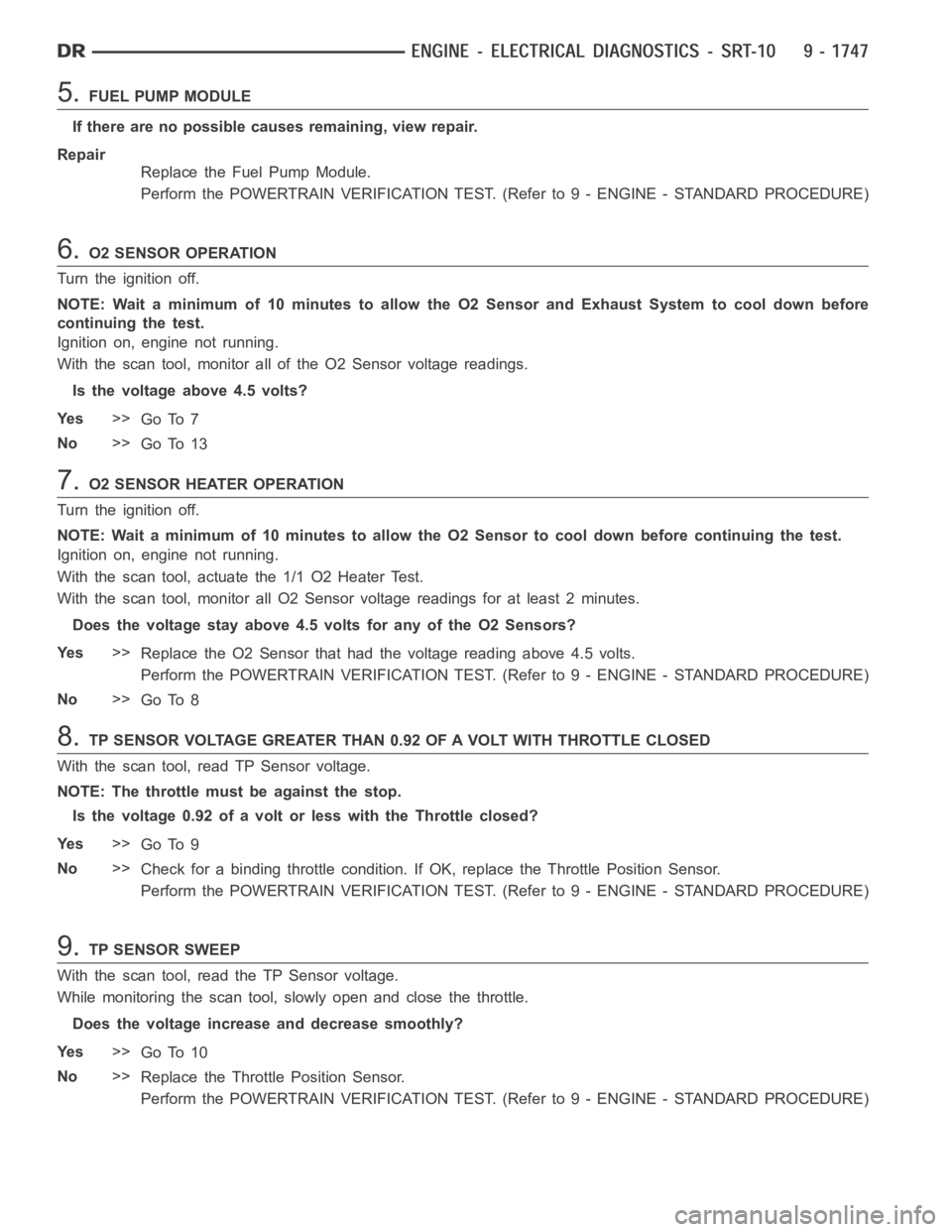
5.FUEL PUMP MODULE
If there are no possible causes remaining, view repair.
Repair
Replace the Fuel Pump Module.
Perform the POWERTRAIN VERIFICATION TEST. (Refer to 9 - ENGINE - STANDARD PROCEDURE)
6.O2 SENSOR OPERATION
Turn the ignition off.
NOTE: Wait a minimum of 10 minutes to allow the O2 Sensor and Exhaust System to cool down before
continuing the test.
Ignition on, engine not running.
With the scan tool, monitor all of the O2 Sensor voltage readings.
Is the voltage above 4.5 volts?
Ye s>>
Go To 7
No>>
Go To 13
7.O2 SENSOR HEATER OPERATION
Turn the ignition off.
NOTE: Wait a minimum of 10 minutes to allow the O2 Sensor to cool down before continuing the test.
Ignition on, engine not running.
With the scan tool, actuate the 1/1 O2 Heater Test.
With the scan tool, monitor all O2 Sensor voltage readings for at least 2 minutes.
Does the voltage stay above 4.5 volts for any of the O2 Sensors?
Ye s>>
Replace the O2 Sensor that had the voltage reading above 4.5 volts.
Perform the POWERTRAIN VERIFICATION TEST. (Refer to 9 - ENGINE - STANDARD PROCEDURE)
No>>
Go To 8
8.TP SENSOR VOLTAGE GREATER THAN 0.92 OF A VOLT WITH THROTTLE CLOSED
With the scan tool, read TP Sensor voltage.
NOTE: The throttle must be against the stop.
Isthevoltage0.92ofavoltorlesswiththeThrottleclosed?
Ye s>>
Go To 9
No>>
Check for a binding throttle condition. If OK, replace the Throttle Position Sensor.
Perform the POWERTRAIN VERIFICATION TEST. (Refer to 9 - ENGINE - STANDARD PROCEDURE)
9.TP SENSOR SWEEP
With the scan tool, read the TP Sensor voltage.
While monitoring the scan tool, slowly open and close the throttle.
Does the voltage increase and decrease smoothly?
Ye s>>
Go To 10
No>>
ReplacetheThrottlePositionSensor.
Perform the POWERTRAIN VERIFICATION TEST. (Refer to 9 - ENGINE - STANDARD PROCEDURE)
Page 1067 of 5267
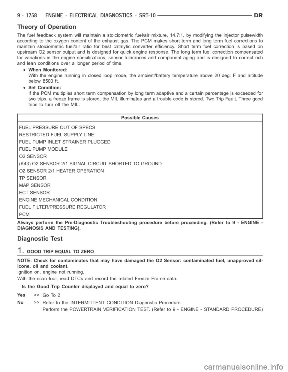
Theory of Operation
The fuel feedback system will maintain a stoiciometric fuel/air mixture,14.7:1, by modifying the injector pulsewidth
according to the oxygen content of the exhaust gas. The PCM makes short termand long term fuel corrections to
maintain stoiciometric fuel/air ratio for best catalytic converter efficiency. Short term fuel correction is based on
upstream O2 sensor output and is designed for quick engine response. The long term fuel correction compensated
for variations in the engine specifications, sensor tolerances and component aging and is designed to correct rich
and lean conditions over a longer period of time.
When Monitored:
With the engine running in closed loop mode, the ambient/battery temperature above 20 deg. F and altitude
below 8500 ft.
Set Condition:
If the PCM multiplies short term compensation by long term adaptive and a certain percentage is exceeded for
two trips, a freeze frame is stored, the MIL illuminates and a trouble code is stored. Two Trip Fault. Three good
trips to turn off the MIL.
Possible Causes
FUEL PRESSURE OUT OF SPECS
RESTRICTED FUEL SUPPLY LINE
FUEL PUMP INLET STRAINER PLUGGED
FUEL PUMP MODULE
O2 SENSOR
(K43) O2 SENSOR 2/1 SIGNAL CIRCUIT SHORTED TO GROUND
O2 SENSOR 2/1 HEATER OPERATION
TP SENSOR
MAP SENSOR
ECT SENSOR
ENGINE MECHANICAL CONDITION
FUEL FILTER/PRESSURE REGULATOR
PCM
Always perform the Pre-Diagnostic Troubleshooting procedure before proceeding. (Refer to 9 - ENGINE -
DIAGNOSIS AND TESTING).
Diagnostic Test
1.GOOD TRIP EQUAL TO ZERO
NOTE: Check for contaminates that may have damaged the O2 Sensor: contaminated fuel, unapproved sil-
icone, oil and coolant.
Ignition on, engine not running.
With the scan tool, read DTCs and record the related Freeze Frame data.
Is the Good Trip Counter displayed and equal to zero?
Ye s>>
Go To 2
No>>
Refer to the INTERMITTENT CONDITION Diagnostic Procedure.
Perform the POWERTRAIN VERIFICATION TEST. (Refer to 9 - ENGINE - STANDARD PROCEDURE)
Page 1068 of 5267
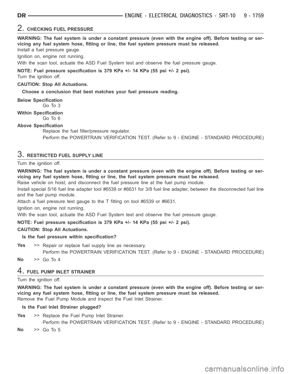
2.CHECKING FUEL PRESSURE
WARNING: The fuel system is under a constant pressure (even with the engineoff). Before testing or ser-
vicing any fuel system hose, fitting or line, the fuel system pressure mustbe released.
Install a fuel pressure gauge.
Ignition on, engine not running.
With the scan tool, actuate the ASD FuelSystem test and observe the fuel pressure gauge.
NOTE: Fuel pressure specification is 379 KPa +/- 14 KPa (55 psi +/- 2 psi).
Turn the ignition off.
CAUTION: Stop All Actuations.
Choose a conclusion that best matches your fuel pressure reading.
Below Specification
Go To 3
Within Specification
Go To 6
Above Specification
Replace the fuel filter/pressure regulator.
Perform the POWERTRAIN VERIFICATION TEST. (Refer to 9 - ENGINE - STANDARD PROCEDURE)
3.RESTRICTED FUEL SUPPLY LINE
Turn the ignition off.
WARNING: The fuel system is under a constant pressure (even with the engineoff). Before testing or ser-
vicing any fuel system hose, fitting or line, the fuel system pressure mustbe released.
Raise vehicle on hoist, and disconnect the fuel pressure line at the fuel pump module.
Install special 5/16 fuel line adapter tool #6539 or #6631 for 3/8 fuel lineadapter, between the disconnected fuel line
and the fuel pump module.
Attach a fuel pressure test gauge to the T fitting on tool #6539 or #6631.
Ignition on, engine not running.
With the scan tool, actuate the ASD FuelSystem test and observe the fuel pressure gauge.
NOTE: Fuel pressure specification is 379 KPa +/- 14 KPa (55 psi +/- 2 psi).
CAUTION: Stop All Actuations.
Is the fuel pressure within specification?
Ye s>>
Repair or replace fuel supply line as necessary.
Perform the POWERTRAIN VERIFICATION TEST. (Refer to 9 - ENGINE - STANDARD PROCEDURE)
No>>
Go To 4
4.FUEL PUMP INLET STRAINER
Turn the ignition off.
WARNING: The fuel system is under a constant pressure (even with the engineoff). Before testing or ser-
vicing any fuel system hose, fitting or line, the fuel system pressure mustbe released.
Remove the Fuel Pump Module and inspect the Fuel Inlet Strainer.
Is the Fuel Inlet Strainer plugged?
Ye s>>
Replace the Fuel Pump Inlet Strainer.
Perform the POWERTRAIN VERIFICATION TEST. (Refer to 9 - ENGINE - STANDARD PROCEDURE)
No>>
Go To 5