2006 DODGE RAM SRT-10 brakes
[x] Cancel search: brakesPage 3761 of 5267
3.CHECKING FOR GOVERNOR PRESSURE ABOVE 6 PSI
Start the engine.
CAUTION: Apply the parking brake.
Warm the transmission to a normal operating temperature above 43° C (110° F).
CAUTION: Firmly apply the brakes.
With the engine RPM at idle, place the gear selector in Drive.
With the scan tool, read the governor pressure.
Is the governor pressure above 41.4 kPa (6 psi)?
Ye s>>
Go To 4
No>>
Go To 11
4.GOVERNOR PRESSURE MATCH GAUGE PRESSURE
Turn the ignition off to the lock position.
Install a 700 kPa (100 psi) pressure gauge to the Governor Pressure Test Port. (Refer to 21 - TRANSMISSION/
TRANSAXLE/AUTOMATIC - 48RE - DIAGNOSIS AND TESTING)
Start the engine.
Warm the transmission to a normal operating temperature above 43° C (110° F).
CAUTION: Firmly apply the brakes.
With the engine RPM at idle, place the gear selector in Drive.
With the scan tool, read the governor pressure and compare the scan tool reading to the pressure gauge reading.
Does the scan tool Governor Pressure reading match the pressure gauge reading within 6.9 kPa (1
psi)?
Ye s>>
Go To 5
No>>
Go To 8
5.CHECK FOR BURNT TRANSMISSION FLUID AND/OR EXCESSIVE DEBRIS IN THE TRANSMISSION OIL
PA N
Turn the ignition off to the lock position.
Remove the transmission oil pan per the Service Information and inspect for burnt transmission fluid and excessive
debris. (Refer to 21 - TRANSMISSION/TRANSAXLE/AUTOMATIC - 48RE/FLUID - STANDARD PROCEDURE)
Is the transmission fluid burnt or does the transmission oil pan contain excessive debris?
Ye s>>
Repair internal transmission as necessary. (Refer to 21 - TRANSMISSION/TRANSAXLE/AUTOMATIC -
48RE - REMOVAL)
Perform RE TRANSMISSION VERIFICATION TEST VER - 1 (DIESEL). (Refer to 21 - TRANSMISSION/
TRANSAXLE/AUTOMATIC - 48RE - STANDARD PROCEDURE)
No>>
Go To 6
6.REPLACE THE GOVERNOR PRESSURE SOLENOID AND CHECK THE VALVE BODY
Replace the Governor Pressure Solenoid per with the Service Information.(Refer to 21 - TRANSMISSION/TRANS-
AXLE/AUTOMATIC - 48RE/GOVERNOR PRESSURE SENSOR - REMOVAL)
Start the engine.
Warm the transmission to a normal operating temperature above 43° C (110° F).
CAUTION: Firmly apply the brakes.
With the engine RPM at idle, place the gear selector in Drive.
Read the governor pressure on the pressure gauge.
Is the governor pressure on the pressure gauge above 41.4 kPa (6 psi) with the engine RPM at idle and
Page 3801 of 5267
5. Line pressure should be 54-60 psi (372-414 kPa) with throttle lever forward and gradually increase to 90-96 psi
(621-662 kPa) as lever is moved rearward.
Test Three - Transmission In D Range Third Gear
This test checks pressure regulation and condition of the clutch circuits. Both test gauges are required for this test.
1. Turn OD switch off.
2. Leave vehicle on hoist and leave Oil Pressure Gauge C-3292 in place at accumulator port.
3. Move Oil Pressure Gauge C-3293-SP over to front servo port for this test.
4. Have helper start and run engine at 1600 rpm for this test.
5. Move transmission shift lever two detents rearward from full forward position. This is D range.
6. Read pressures on both gauges as transmission throttle lever is gradually moved from full forward to full rear-
ward position:
Line pressure at accumulator in D range third gear, should be 54-60 psi (372-414 kPa) with throttle lever for-
ward and increase as lever is moved rearward.
Front servo pressure in D range third gear, should be within 3 psi (21 kPa) ofline pressure up to kickdown
point.
Test Four - Transmission In Reverse
This test checks pump output, pressure regulation and the front clutch andrear servo circuits. Use 300 psi Oil
Pressure Gauge C-3293-SP for this test.
1. Leave vehicle on hoist and leave Oil Pressure Gauge C-3292 in place at accumulator port.
2. Move 300 psi Oil Pressure Gauge C-3293-SP back to rear servo port.
3. Have helper start and run engine at 1600 rpm for test.
4. Move transmission shift lever four detents rearward from full forward position. This is Reverse range.
5. Move transmission throttle lever fully forward then fully rearward andnote reading at Gauge C-3293-SP.
6. Pressure should be 145 - 175 psi (1000-1207 kPa) with throttle lever forward and increase to 230 - 280 psi
(1586-1931 kPa) as lever is gradually moved rearward.
Test Five - Governor Pressure
This test checks governor operation by measuring governor pressure response to changes in vehicle speed. It is
usually not necessary to check governor operation unless shift speeds areincorrect or if the transmission will not
downshift. The test should be performed on the road or on a hoist that will allow the rear wheels to rotate freely.
1. Move 100 psi Oil Pressure Gauge C-3292 to governor pressure port.
2. Move transmission shift lever two detents rearward from full forward position. This is D range.
3. Have helper start and run engine at curb idle speed. Then firmly apply service brakes so wheels will not rotate.
4. Note governor pressure:
Governor pressure should be no more than 20.6 kPa (3 psi) at curb idle speed and wheels not rotating.
If pressure exceeds 20.6 kPa (3 psi), a fault exists in governor pressure control system.
5. Release brakes, slowly increase engine speed, and observe speedometerand pressure test gauge (do not
exceed 30 mph on speedometer). Governor pressure should increase in proportion to vehicle speed. Or approx-
imately 6.89 kPa (1 psi) for every 1 mph.
6. Governor pressure rise should be smooth and drop back to no more than 20.6kPa (3 psi), after engine returns
to curb idle and brakes are applied to prevent wheels from rotating.
7. Compare results of pressure test with analysis chart.
Test Six - Transmission In Overdrive Fourth Gear
This test checks line pressure at the overdrive clutch in fourth gear range. Use 300 psi Oil Pressure Gauge
C-3293-SP for this test. The test should be performed on the road or on a chassis dyno.
1. Remove tachometer; it is not needed for this test.
2. Move 300 psi Oil Pressure Gauge to overdrive clutch pressure test port. Then remove other gauge and reinstall
test port plug.
Page 3867 of 5267
ADJUSTMENT PROCEDURE
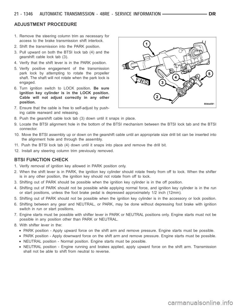
1. Remove the steering column trim as necessary for
access to the brake transmission shift interlock.
2. Shift the transmission into the PARK position.
3. Pull upward on both the BTSI lock tab (4) and the
gearshift cable lock tab (3).
4. Verify that the shift lever is in the PARK position.
5. Verify positive engagement of the transmission
park lock by attempting to rotate the propeller
shaft. The shaft will not rotate when the park lock is
engaged.
6. Turn ignition switch to LOCK position.Be sure
ignition key cylinder is in the LOCK position.
Cable will not adjust correctly in any other
position.
7. Ensure that the cable is free to self-adjust by push-
ing cable rearward and releasing.
8. Push the gearshift cable lock tab (3) down until it snaps in place.
9. Locate the BTSI alignment hole in the bottom of the BTSI mechanism betweentheBTSIlocktabandtheBTSI
connector.
10. Move the BTSI assembly up or down on the gearshift cable until an appropriate size drill bit can be inserted into
the alignment hole and through the assembly.
11. Push the BTSI lock tab (4) down until it snaps into place and remove the drill bit.
12. Install any steering column trim previously removed.
BTSI FUNCTION CHECK
1. Verify removal of ignition key allowed in PARK position only.
2. When the shift lever is in PARK, the ignition key cylinder should rotate freely from off to lock. When the shifter
is in any other position, the ignition key should not rotate from off to lock.
3. Shifting out of PARK should be possible when the ignition key cylinder isin the off position.
4. Shifting out of PARK should not be possible while applying normal force,and ignition key cylinder is in the run
or start positions, unless the foot brake pedal is depressed approximately1/2inch(12mm).
5. Shifting out of PARK should not be possible when the ignition key cylinder is in the accessory or lock position.
6. Shifting between any gear and NEUTRAL, or PARK, may be done without depressing foot brake with ignition
switch in run or start positions.
7. Engine starts must be possible with shifter lever in PARK or NEUTRAL positions only. Engine starts must not be
possible in any position other than PARK or NEUTRAL.
8. With shifter lever in the:
PARK position - Apply upward force on the shift arm and remove pressure. Enginestartsmustbepossible.
PARK position - Apply downward force on the shift arm and remove pressure. Engine starts must be possible.
NEUTRAL position - Normal position. Engine starts must be possible.
NEUTRAL position - Engine running and brakes applied, apply upward force on the shift arm. Transmission
shall not be able to shift from neutral to reverse.
Page 3875 of 5267
After the fluid has been checked, seat the dipstick fully to seal out water and dirt.
The transmission has a dipstick to check oil level. It is located on the right side of the engine. Be sure to wipe all
dirt from dipstick handle before removing.
Fluid level is checked with the engine running at curb idle speed, the transmissioninNEUTRALandthetransmis-
sion fluid at normal operating temperature.The engine should be running at idle speed for at least one minute,
with the vehicle on level ground.
The transmission fluid level can be checked two ways.
PROCEDURE ONE
1. Transmission fluid must be at normal operating
temperature for accurate fluid level check. Drive
vehicle if necessary to bring fluid temperature up to
normal hot operating temperature of 82°C (180°F).
2. Position vehicle on level surface.
3. Start and run engine at curb idle speed.
4. Apply parking brakes.
5. Shift transmission momentarily into all gear ranges.
Then shift transmission back to NEUTRAL.
6. Clean top of filler tube and dipstick to keep dirt from entering tube.
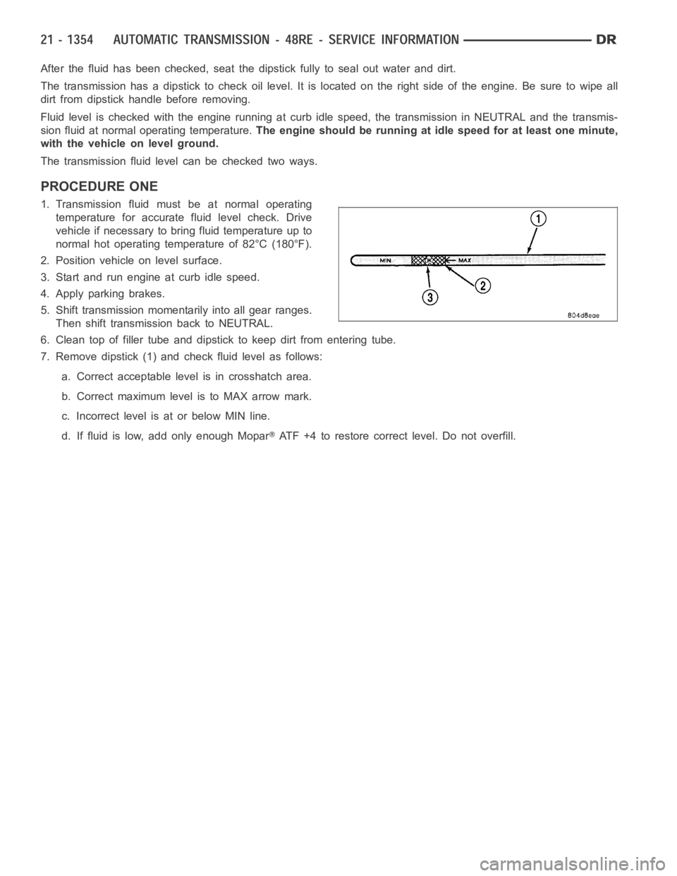
7. Remove dipstick (1) and check fluid level as follows:
a. Correct acceptable level is in crosshatch area.
b. Correct maximum level is to MAX arrow mark.
c. Incorrect level is at or below MIN line.
d. If fluid is low, add only enough Mopar
ATF +4 to restore correct level. Do not overfill.
Page 3878 of 5267
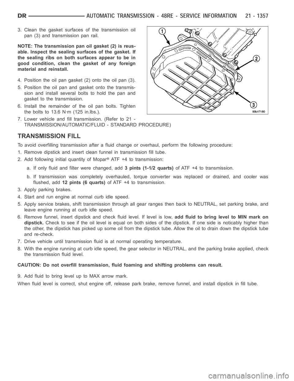
3. Clean the gasket surfaces of the transmission oil
pan (3) and transmission pan rail.
NOTE: The transmission pan oil gasket (2) is reus-
able. Inspect the sealing surfaces of the gasket. If
the sealing ribs on both surfaces appear to be in
good condition, clean the gasket of any foreign
material and reinstall.
4. Position the oil pan gasket (2) onto the oil pan (3).
5. Position the oil pan and gasket onto the transmis-
sion and install several bolts to hold the pan and
gasket to the transmission.
6. Install the remainder of the oil pan bolts. Tighten
the bolts to 13.6 Nꞏm (125 in.lbs.).
7. Lower vehicle and fill transmission. (Refer to 21 -
TRANSMISSION/AUTOMATIC/FLUID - STANDARD PROCEDURE)
TRANSMISSION FILL
To avoid overfilling transmission after a fluid change or overhaul, perform the following procedure:
1. Remove dipstick and insert clean funnel in transmission fill tube.
2. Add following initial quantity of Mopar
ATF+4totransmission:
a. If only fluid and filter were changed, add3 pints (1-1/2 quarts)of ATF +4 to transmission.
b. If transmission was completely overhauled, torque converter was replaced or drained, and cooler was
flushed, add12 pints (6 quarts)of ATF +4 to transmission.
3. Apply parking brakes.
4. Start and run engine at normal curb idle speed.
5. Apply service brakes, shift transmission through all gear ranges then back to NEUTRAL, set parking brake, and
leave engine running at curb idle speed.
6. Remove funnel, insert dipstick andcheck fluid level. If level is low,add fluid to bring level to MIN mark on
dipstick.Check to see if the oil level is equal on both sides of the dipstick. If one side is noticably higher than
the other, the dipstick has picked up some oil from the dipstick tube. Allowthe oil to drain down the dipstick tube
and re-check.
7. Drive vehicle until transmission fluid is at normal operating temperature.
8. With the engine running at curb idle speed, the gear selector in NEUTRAL,and the parking brake applied, check
the transmission fluid level.
CAUTION: Do not overfill transmission, fluid foaming and shifting problems can result.
9. Add fluid to bring level up to MAX arrow mark.
When fluid level is correct, shut engine off, release park brake, remove funnel, and install dipstick in fill tube.
Page 3887 of 5267
CABLE-GEARSHIFT
DIAGNOSIS AND TESTING - GEARSHIFT CABLE
1. Engine starts must be possible with shift lever in PARK or NEUTRAL positions only. Engine starts must not be
possible in any other gear position.
2. With the shift lever in the:
a. PARK position - Apply upward force on the shift arm and remove pressure. Engine starts must be possible.
b. PARK position - Apply downward force on the shift arm and remove pressure. Engine starts must be pos-
sible.
c. NEUTRAL position - Normal position. Engine starts must be possible.
d. NEUTRAL position - Engine running and brakes applied, apply upward forceontheshiftarm.Transmission
shall not be able to shift from neutral to reverse.
REMOVAL
1. Shift transmission into PARK.
2. Raise vehicle.
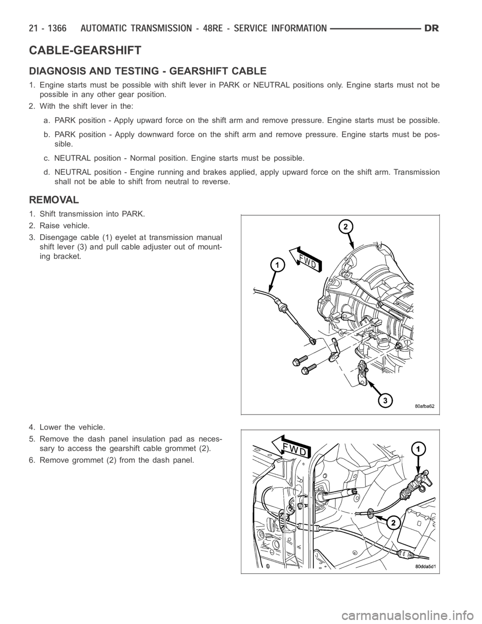
3. Disengage cable (1) eyelet at transmission manual
shift lever (3) and pull cable adjuster out of mount-
ing bracket.
4. Lower the vehicle.
5. Remove the dash panel insulation pad as neces-
sary to access the gearshift cable grommet (2).
6. Remove grommet (2) from the dash panel.
Page 4322 of 5267
Radial-ply tires have the same load-carrying capacity as other types of tires of the same size. They also use the
same recommended inflation pressures.
The use of oversized tires, either in the front or rear of the vehicle, can cause vehicle drive train failure. This could
also cause inaccurate wheel speed signals when the vehicle is equipped with Anti-Lock Brakes.
The use of tires from different manufactures on the same vehicle is NOT recommended. The proper tire pressure
should be maintained on all four tires.
TIRE PRESSURE FOR HIGH SPEEDS
For proper tire pressure specification refer to the Owners Manual.
REPLACEMENT TIRES
The original equipment tires provide a proper balance of many characteristics such as:
Ride
Noise
Handling
Durability
Tread life
Traction
Rolling resistance
Speed capability
It is recommended that tires equivalent to the original equipment tires beused when replacement is needed.
Failure to use equivalent replacement tires may adversely affect the safety and handling of the vehicle.
The use of oversize tires may cause interference with vehicle components.Under extremes of suspension and
steering travel, interference with vehicle components may cause tire damage.
WARNING: Failure to equip the vehicle with tires having adequate speed capability can result in sudden tire
failure.
TIRE INFLATION PRESSURES
WARNING: Over or under inflated tires can affect
vehicle handling and tread wear. This may cause
the tire to fail suddenly, resulting in loss of vehicle
control.
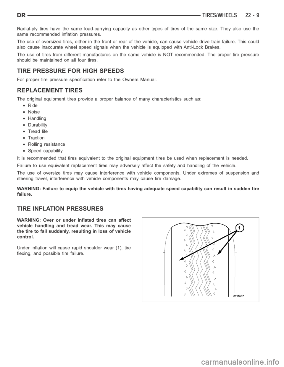
Under inflation will cause rapid shoulder wear (1), tire
flexing, and possible tire failure.
Page 4333 of 5267

STUDS
REMOVAL
1. Raise and support the vehicle.
2. Remove the wheel and tire assembly.
3. Remove the brake caliper, caliper adapter and
rotor, (Refer to 5 - BRAKES/HYDRAULIC/ME-
CHANICAL/ROTORS - REMOVAL).
4. Remove the wheel speed sensor from the hub.
5. Press the stud from the hub using remover
C-4150A (1).
6. Remove the stud (2) from the hub (1) through the
backing plate access hole (3).
INSTALLATION
1. Install the new stud (2) into the hub flange (1).
2. Install three proper sized washers onto the stud,
then install lug nut with the flat side of the nut
against the washers.
3. Tighten the lug nut until the stud is pulled into the
hub flange. Verify that the stud is properly seated
into the flange.
4. Remove the lug nut and washers.
5. Install the brake rotor, caliper adapter, and caliper,
(Refer to 5 - BRAKES/HYDRAULIC/MECHANICAL/
ROTORS - INSTALLATION).
6. Install the wheel speed sensor.
7. Install the wheel and tire assembly, use new lug nut on the stud or studs that were replaced.