2006 DODGE RAM SRT-10 brakes
[x] Cancel search: brakesPage 3295 of 5267
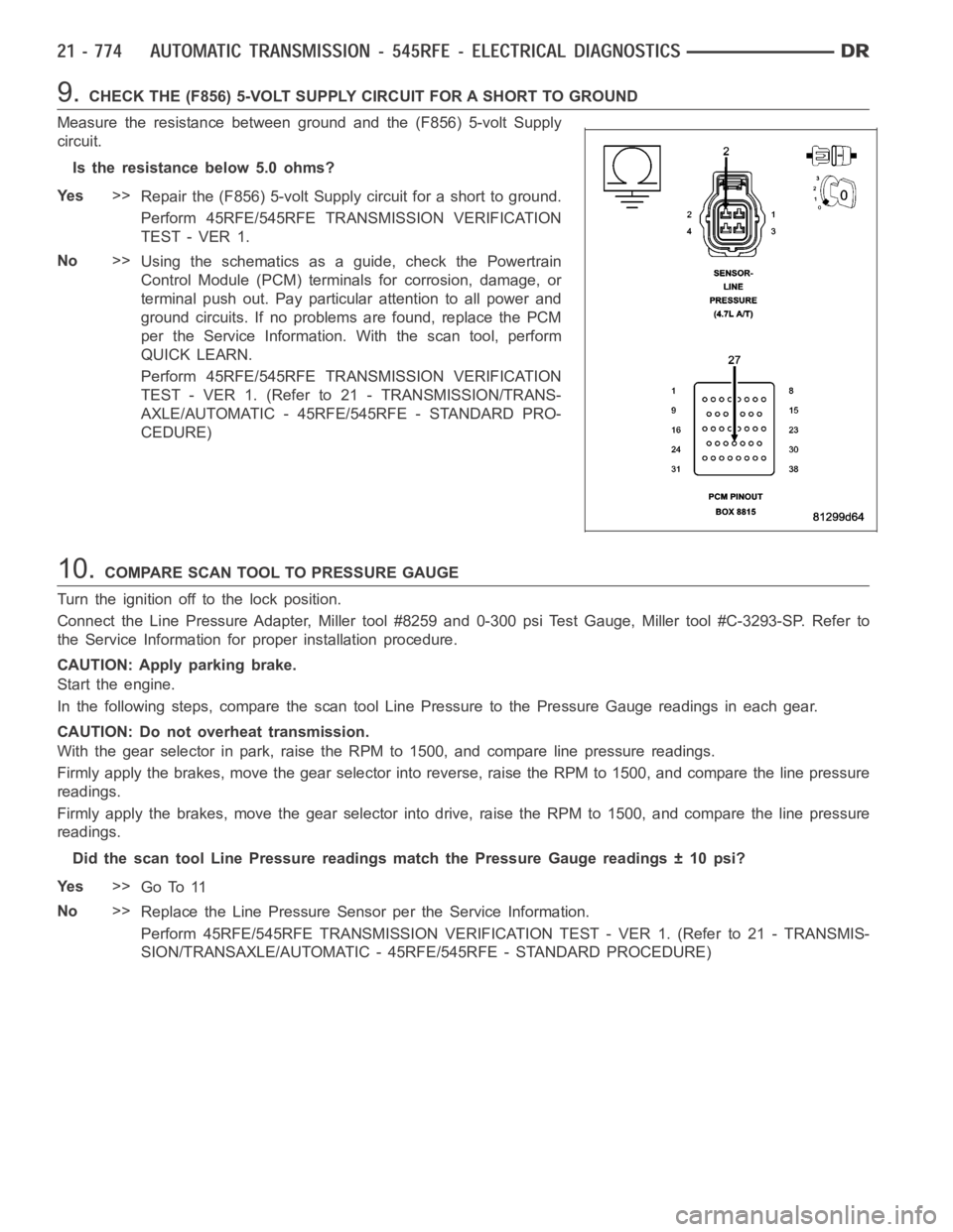
9.CHECK THE (F856) 5-VOLT SUPPLY CIRCUIT FOR A SHORT TO GROUND
Measure the resistance between ground and the (F856) 5-volt Supply
circuit.
Is the resistance below 5.0 ohms?
Ye s>>
Repair the (F856) 5-volt Supply circuit for a short to ground.
Perform 45RFE/545RFE TRANSMISSION VERIFICATION
TEST - VER 1.
No>>
Using the schematics as a guide, check the Powertrain
Control Module (PCM) terminals for corrosion, damage, or
terminal push out. Pay particular attention to all power and
ground circuits. If no problems are found, replace the PCM
per the Service Information.With the scan tool, perform
QUICK LEARN.
Perform 45RFE/545RFE TRANSMISSION VERIFICATION
TEST - VER 1. (Refer to 21 - TRANSMISSION/TRANS-
AXLE/AUTOMATIC - 45RFE/545RFE - STANDARD PRO-
CEDURE)
10.COMPARE SCAN TOOL TO PRESSURE GAUGE
Turn the ignition off to the lock position.
Connect the Line Pressure Adapter, Miller tool #8259 and 0-300 psi Test Gauge, Miller tool #C-3293-SP. Refer to
the Service Information for proper installation procedure.
CAUTION: Apply parking brake.
Start the engine.
In the following steps, compare thescan tool Line Pressure to the PressureGauge readings in each gear.
CAUTION: Do not overheat transmission.
With the gear selector in park, raise the RPM to 1500, and compare line pressure readings.
Firmly apply the brakes, move the gear selector into reverse, raise the RPMto 1500, and compare the line pressure
readings.
Firmly apply the brakes, move the gear selector into drive, raise the RPM to1500, and compare the line pressure
readings.
Did the scan tool Line Pressure readings match the Pressure Gauge readings±10psi?
Ye s>>
Go To 11
No>>
Replace the Line Pressure Sensor per the Service Information.
Perform 45RFE/545RFE TRANSMISSION VERIFICATION TEST - VER 1. (Refer to 21- TRANSMIS-
SION/TRANSAXLE/AUTOMATIC - 45RFE/545RFE - STANDARD PROCEDURE)
Page 3429 of 5267
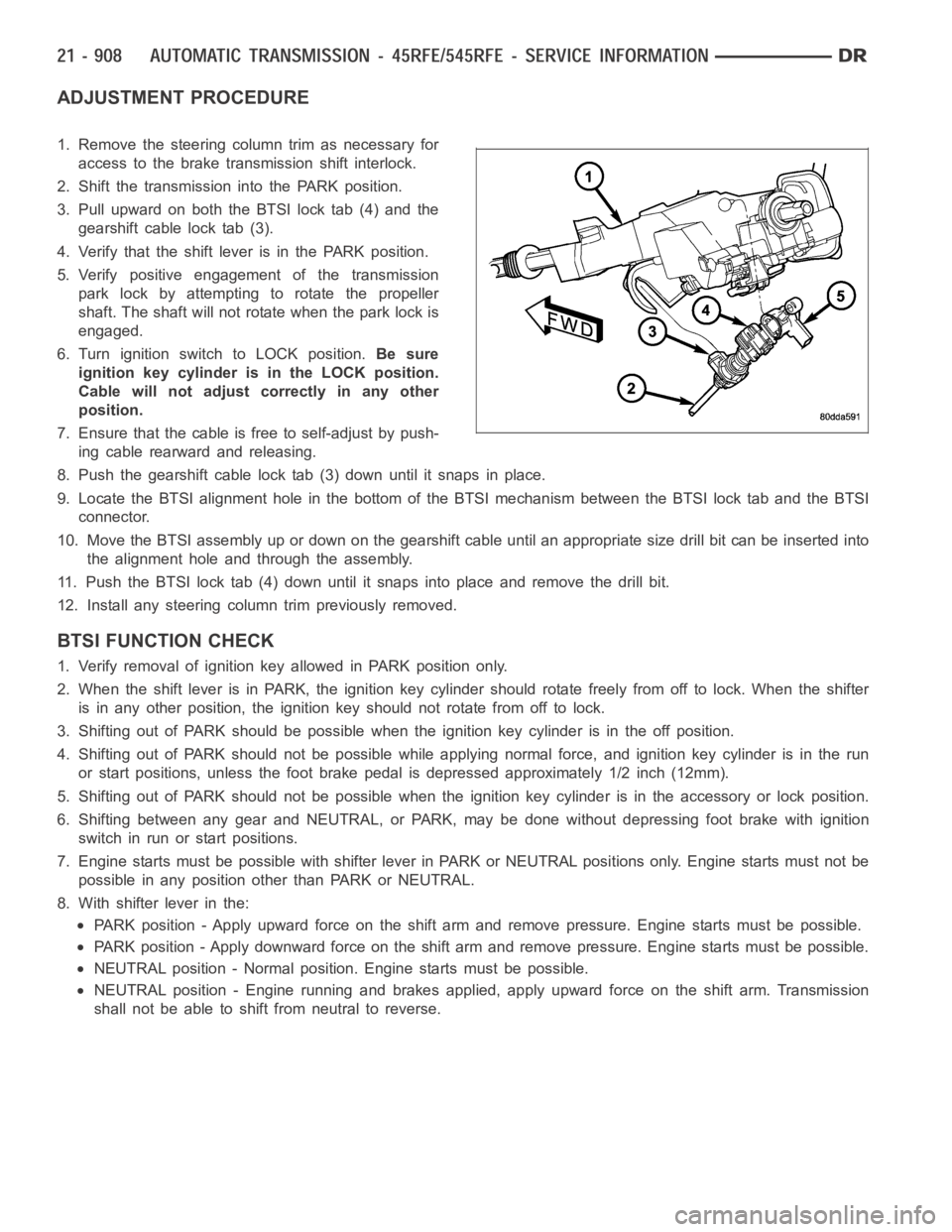
ADJUSTMENT PROCEDURE
1. Remove the steering column trim as necessary for
access to the brake transmission shift interlock.
2. Shift the transmission into the PARK position.
3. Pull upward on both the BTSI lock tab (4) and the
gearshift cable lock tab (3).
4. Verify that the shift lever is in the PARK position.
5. Verify positive engagement of the transmission
park lock by attempting to rotate the propeller
shaft. The shaft will not rotate when the park lock is
engaged.
6. Turn ignition switch to LOCK position.Be sure
ignition key cylinder is in the LOCK position.
Cable will not adjust correctly in any other
position.
7. Ensure that the cable is free to self-adjust by push-
ing cable rearward and releasing.
8. Push the gearshift cable lock tab (3) down until it snaps in place.
9. Locate the BTSI alignment hole in the bottom of the BTSI mechanism betweentheBTSIlocktabandtheBTSI
connector.
10. Move the BTSI assembly up or down on the gearshift cable until an appropriate size drill bit can be inserted into
the alignment hole and through the assembly.
11. Push the BTSI lock tab (4) down until it snaps into place and remove the drill bit.
12. Install any steering column trim previously removed.
BTSI FUNCTION CHECK
1. Verify removal of ignition key allowed in PARK position only.
2. When the shift lever is in PARK, the ignition key cylinder should rotate freely from off to lock. When the shifter
is in any other position, the ignition key should not rotate from off to lock.
3. Shifting out of PARK should be possible when the ignition key cylinder isin the off position.
4. Shifting out of PARK should not be possible while applying normal force,and ignition key cylinder is in the run
or start positions, unless the foot brake pedal is depressed approximately1/2inch(12mm).
5. Shifting out of PARK should not be possible when the ignition key cylinder is in the accessory or lock position.
6. Shifting between any gear and NEUTRAL, or PARK, may be done without depressing foot brake with ignition
switch in run or start positions.
7. Engine starts must be possible with shifter lever in PARK or NEUTRAL positions only. Engine starts must not be
possible in any position other than PARK or NEUTRAL.
8. With shifter lever in the:
PARK position - Apply upward force on the shift arm and remove pressure. Enginestartsmustbepossible.
PARK position - Apply downward force on the shift arm and remove pressure. Engine starts must be possible.
NEUTRAL position - Normal position. Engine starts must be possible.
NEUTRAL position - Engine running and brakes applied, apply upward force on the shift arm. Transmission
shall not be able to shift from neutral to reverse.
Page 3434 of 5267
CABLE-GEARSHIFT
DIAGNOSIS AND TESTING - GEARSHIFT CABLE
1. Engine starts must be possible with shift lever in PARK or NEUTRAL positions only. Engine starts must not be
possible in any other gear position.
2. With the shift lever in the:
a. PARK position - Apply upward force on the shift arm and remove pressure. Engine starts must be possible.
b. PARK position - Apply downward force on the shift arm and remove pressure. Engine starts must be pos-
sible.
c. NEUTRAL position - Normal position. Engine starts must be possible.
d. NEUTRAL position - Engine running and brakes applied, apply upward forceontheshiftarm.Transmission
shall not be able to shift from neutral to reverse.
REMOVAL
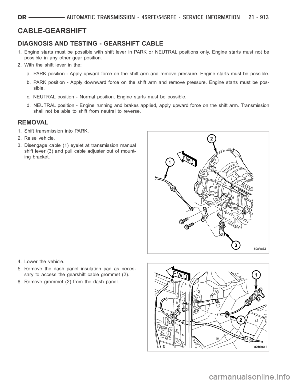
1. Shift transmission into PARK.
2. Raise vehicle.
3. Disengage cable (1) eyelet at transmission manual
shift lever (3) and pull cable adjuster out of mount-
ing bracket.
4. Lower the vehicle.
5. Remove the dash panel insulation pad as neces-
sary to access the gearshift cable grommet (2).
6. Remove grommet (2) from the dash panel.
Page 3512 of 5267

3.COMPARE THE TRANSMISSION TEMPERATURE TO ENGINE COOLANT TEMPERATURE
NOTE: To test the transmission temperature sensor, the engine and transmission temperature must be at or
below 29.4° C (85° F).
With the scan tool, read the Transmission and Engine temperatures.
Is the transmission temperature within 5° C (9° F) of the engine coolant temperature?
Ye s>>
Go To 4
No>>
Go To 5
4.CHECK IF THE TRANSMISSION TEMPERATURE INCREASES 15 DEGREES OVER 10 MINUTEPERIOD
NOTE: To test the transmission temperature sensor, the engine and transmission temperature must be at or
below 29.4° C (85° F).
CAUTION: Apply the parking brake.
Start the engine, firmly apply the brakes and allow the engine to idle in Drive.
With the scan tool, monitor the Transmission Temperature.
NOTE: If the transmission temperature sensor is working properly, the transmission temperature should rise
at least 8° C (15° F) within a ten minute period.
Did the transmission temperature increase at a steady rate and rise at least 8° C (15° F) over a 10
minute period?
Ye s>>
Go To 6
No>>
Go To 5
5.CHECK THE TRANSMISSION TEMPERATURE SENSOR
TYPICAL VALUES FOR TRANSMISSION TEMPERATURE SENSOR
TEMPERATURE MIN TO MAX OHM RANGE
-40° C (-40° F) 1094 to 1176 ohms
0.0° C (32° F) 1587 to 1672 ohms
25° C (77° F) 1960 to 2040 ohms
70° C (158° F) 2709 to 2860 ohms
0° C (212° F) 3284 to 3500 ohms
120° C (120° F) 3684 to 3950 ohms
150° C (302° F) 4110 to 4450 ohms
Page 3563 of 5267
Theory of Operation
The Torque Converter Clutch (TCC) Solenoid is used to engage the TCC which improves fuel economy. The Over-
drive Solenoid is used to engage the gear change from third to Overdrive.
When Monitored:
Continuously with the ignition on and the engine running.
Set Condition:
This DTC will set if the expected engine RPM drop does not occur within 4 seconds of the gear change being
requested by the PCM three consecutive failed tests.
Possible Causes
FLUID LEVEL AND CONDITION - EXCESSIVE DEBRIS OR BURNT
3-4 SHIFT SOLENOID
INTERNAL TRANSMISSION FAILURE
Always perform the Pre-Diagnostic Troubleshooting procedure before proceeding. (Refer to 21 - TRANSMIS-
SION/TRANSAXLE/AUTOMATIC - 48RE - STANDARD PROCEDURE)
Diagnostic Test
1.CHECK IF THERE ANY TRANSMISSION CONTROL DTCS PRESENT
Ignition on, engine not running.
With the scan tool, read Engine DTCs.
Are there any TIPM TCM Power Control Circuit DTCs also present?
Ye s>>
Refer to the Transmission or Engine category and perform the appropriate symptom(s).
No>>
Go To 2
2.CHECK IF THE DTC IS CURRENT
With the scan tool, read Engine DTCs.
Record the Freeze Frame data for the reported DTC.
With the scan tool, erase DTCs.
Turn the ignition off to the lock position.
Using the Freeze Frame data recorded earlier, try to duplicate the conditions in which the DTC originally set.
NOTE: It may be necessary to road test the vehicle to duplicate the originalset conditions.
With the scan tool, read Engine DTCs.
Did the DTC reset?
Ye s>>
Go To 3
No>>
Go To 6
3.CHECK THE GOVERNOR AND OVERDRIVE PRESSURE
Turn the ignition off to the lock position.
Connect a 0 - 2068 KPa (0 - 300 PSI) pressure gauge to the Overdrive Clutch test port.
Connect another 0 - 2068 KPa (0 - 300 PSI) pressure gauge to the Governor Pressure test port. (Refer to 21 -
TRANSMISSION/TRANSAXLE/AUTOMATIC - 48RE - DIAGNOSIS AND TESTING)
Start the engine and allow the transmission temperature to rise to normal operating temperature.
CAUTION: Apply the parking brake.
Firmly apply the brakesand place the gear selector in Drive.
While observing the pressure gauges, with the scan tool, select 4th gear from the Gov and 3-4 Shift Valve Test.
Page 3564 of 5267
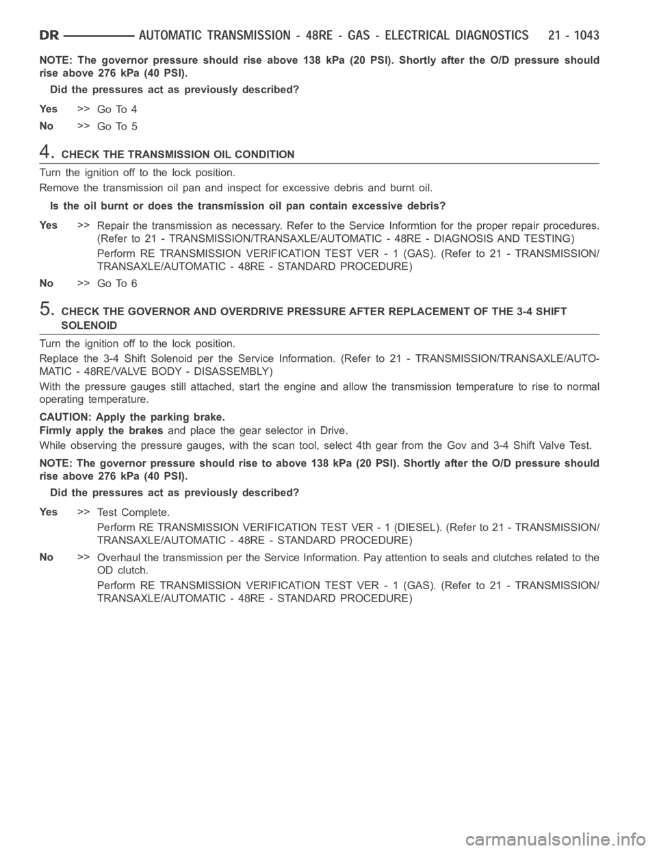
NOTE: The governor pressure should rise above 138 kPa (20 PSI). Shortly after the O/D pressure should
rise above 276 kPa (40 PSI).
Did the pressures act as previously described?
Ye s>>
Go To 4
No>>
Go To 5
4.CHECK THE TRANSMISSION OIL CONDITION
Turn the ignition off to the lock position.
Remove the transmission oil pan and inspect for excessive debris and burntoil.
Is the oil burnt or does the transmission oil pan contain excessive debris?
Ye s>>
Repair the transmission as necessary. Refer to the Service Informtion forthe proper repair procedures.
(Refer to 21 - TRANSMISSION/TRANSAXLE/AUTOMATIC - 48RE - DIAGNOSIS AND TESTING)
Perform RE TRANSMISSION VERIFICATION TEST VER - 1 (GAS). (Refer to 21 - TRANSMISSION/
TRANSAXLE/AUTOMATIC - 48RE - STANDARD PROCEDURE)
No>>
Go To 6
5.CHECK THE GOVERNOR AND OVERDRIVE PRESSURE AFTER REPLACEMENT OF THE 3-4 SHIFT
SOLENOID
Turn the ignition off to the lock position.
Replace the 3-4 Shift Solenoid per the Service Information. (Refer to 21 - TRANSMISSION/TRANSAXLE/AUTO-
MATIC - 48RE/VALVE BODY - DISASSEMBLY)
With the pressure gauges still attached, start the engine and allow the transmission temperature to rise to normal
operating temperature.
CAUTION: Apply the parking brake.
Firmly apply the brakesand place the gear selector in Drive.
While observing the pressure gauges, with the scan tool, select 4th gear from the Gov and 3-4 Shift Valve Test.
NOTE: The governor pressure should rise to above 138 kPa (20 PSI). Shortly after the O/D pressure should
rise above 276 kPa (40 PSI).
Did the pressures act as previously described?
Ye s>>
Te s t C o m p l e t e .
Perform RE TRANSMISSION VERIFICATION TEST VER - 1 (DIESEL). (Refer to 21 - TRANSMISSION/
TRANSAXLE/AUTOMATIC - 48RE - STANDARD PROCEDURE)
No>>
Overhaul the transmission per the Service Information. Pay attention to seals and clutches related to the
OD clutch.
Perform RE TRANSMISSION VERIFICATION TEST VER - 1 (GAS). (Refer to 21 - TRANSMISSION/
TRANSAXLE/AUTOMATIC - 48RE - STANDARD PROCEDURE)
Page 3590 of 5267
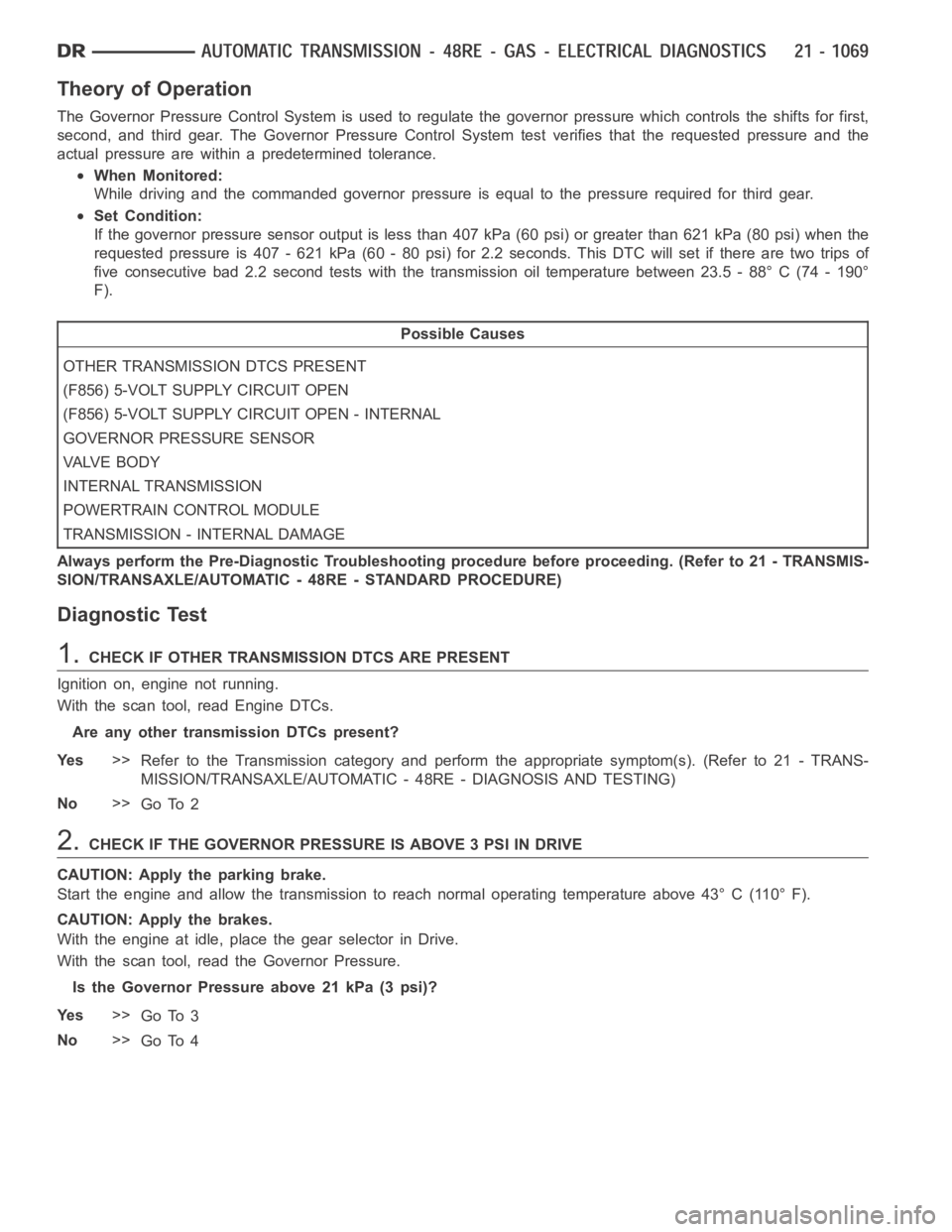
Theory of Operation
The Governor Pressure Control System is used to regulate the governor pressure which controls the shifts for first,
second, and third gear. The Governor Pressure Control System test verifies that the requested pressure and the
actual pressure are within a predetermined tolerance.
When Monitored:
While driving and the commanded governor pressure is equal to the pressurerequired for third gear.
Set Condition:
If the governor pressure sensor output is less than 407 kPa (60 psi) or greater than 621 kPa (80 psi) when the
requested pressure is 407 - 621 kPa (60 - 80 psi) for 2.2 seconds. This DTC will set if there are two trips of
five consecutive bad 2.2 second tests with the transmission oil temperature between 23.5 - 88° C (74 - 190°
F).
Possible Causes
OTHER TRANSMISSION DTCS PRESENT
(F856) 5-VOLT SUPPLY CIRCUIT OPEN
(F856) 5-VOLT SUPPLY CIRCUIT OPEN - INTERNAL
GOVERNOR PRESSURE SENSOR
VA LV E B O D Y
INTERNAL TRANSMISSION
POWERTRAIN CONTROL MODULE
TRANSMISSION - INTERNAL DAMAGE
Always perform the Pre-Diagnostic Troubleshooting procedure before proceeding. (Refer to 21 - TRANSMIS-
SION/TRANSAXLE/AUTOMATIC - 48RE - STANDARD PROCEDURE)
Diagnostic Test
1.CHECK IF OTHER TRANSMISSION DTCS ARE PRESENT
Ignition on, engine not running.
With the scan tool, read Engine DTCs.
Are any other transmission DTCs present?
Ye s>>
Refer to the Transmission category and perform the appropriate symptom(s). (Refer to 21 - TRANS-
MISSION/TRANSAXLE/AUTOMATIC - 48RE - DIAGNOSIS AND TESTING)
No>>
Go To 2
2.CHECK IF THE GOVERNOR PRESSURE IS ABOVE 3 PSI IN DRIVE
CAUTION: Apply the parking brake.
Start the engine and allow the transmission to reach normal operating temperature above 43° C (110° F).
CAUTION: Apply the brakes.
With the engine at idle, place the gear selector in Drive.
With the scan tool, read the Governor Pressure.
Is the Governor Pressure above 21 kPa (3 psi)?
Ye s>>
Go To 3
No>>
Go To 4
Page 3591 of 5267
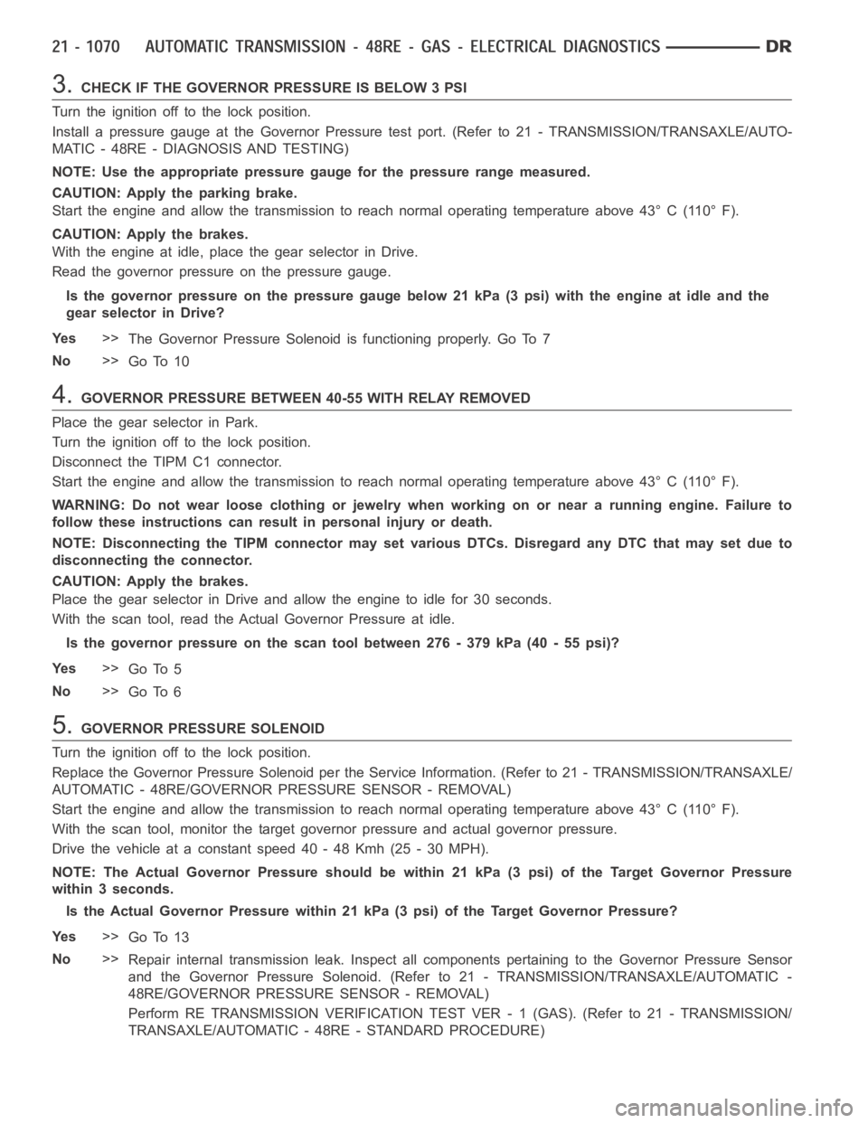
3.CHECK IF THE GOVERNOR PRESSURE IS BELOW 3 PSI
Turn the ignition off to the lock position.
Install a pressure gauge at the Governor Pressure test port. (Refer to 21 - TRANSMISSION/TRANSAXLE/AUTO-
MATIC - 48RE - DIAGNOSIS AND TESTING)
NOTE: Use the appropriate pressure gauge for the pressure range measured.
CAUTION: Apply the parking brake.
Start the engine and allow the transmission to reach normal operating temperature above 43° C (110° F).
CAUTION: Apply the brakes.
With the engine at idle, place the gear selector in Drive.
Read the governor pressure on the pressure gauge.
Is the governor pressure on the pressure gauge below 21 kPa (3 psi) with the engine at idle and the
gear selector in Drive?
Ye s>>
The Governor Pressure Solenoid is functioning properly. Go To 7
No>>
Go To 10
4.GOVERNOR PRESSURE BETWEEN 40-55 WITH RELAY REMOVED
Place the gear selector in Park.
Turn the ignition off to the lock position.
Disconnect the TIPM C1 connector.
Start the engine and allow the transmission to reach normal operating temperature above 43° C (110° F).
WARNING: Do not wear loose clothing or jewelry when working on or near a running engine. Failure to
follow these instructions can result in personal injury or death.
NOTE: Disconnecting the TIPM connector may set various DTCs. Disregard anyDTCthatmaysetdueto
disconnecting the connector.
CAUTION: Apply the brakes.
Place the gear selector in Drive and allow the engine to idle for 30 seconds.
With the scan tool, read the Actual Governor Pressure at idle.
Is the governor pressure on the scan tool between 276 - 379 kPa (40 - 55 psi)?
Ye s>>
Go To 5
No>>
Go To 6
5.GOVERNOR PRESSURE SOLENOID
Turn the ignition off to the lock position.
Replace the Governor Pressure Solenoid per the Service Information. (Refer to 21 - TRANSMISSION/TRANSAXLE/
AUTOMATIC - 48RE/GOVERNOR PRESSURE SENSOR - REMOVAL)
Start the engine and allow the transmission to reach normal operating temperature above 43° C (110° F).
With the scan tool, monitor the target governor pressure and actual governor pressure.
Drivethevehicleataconstantspeed40-48Kmh(25-30MPH).
NOTE: The Actual Governor Pressure should be within 21 kPa (3 psi) of the Target Governor Pressure
within 3 seconds.
Is the Actual Governor Pressure within 21 kPa (3 psi) of the Target GovernorPressure?
Ye s>>
Go To 13
No>>
Repair internal transmission leak. Inspect all components pertaining tothe Governor Pressure Sensor
and the Governor Pressure Solenoid. (Refer to 21 - TRANSMISSION/TRANSAXLE/AUTOMATIC -
48RE/GOVERNOR PRESSURE SENSOR - REMOVAL)
Perform RE TRANSMISSION VERIFICATION TEST VER - 1 (GAS). (Refer to 21 - TRANSMISSION/
TRANSAXLE/AUTOMATIC - 48RE - STANDARD PROCEDURE)