Page 573 of 5267
6.(K37) SIGNAL CIRCUIT OPEN
Measure the resistance between the signal (K37) circuit in the Map sen-
sor harness connector with the (K37) signal circuit in the ECM harness
connector.
Is the resistance less than 10 Ohms?
Ye s>>
Go To 7
No>>
Repair or replace the engine harness.
Perform POWERTRAIN VERIFICATION TEST VER - 1
(DIESEL). (Refer to 8 - ELECTRICAL/ELECTRONIC CON-
TROL MODULES/ENGINE CONTROL MODULE - DIAG-
NOSIS AND TESTING)
7.(F855) 5-VOLT SUPPLY CIRCUIT OPEN
Measure the resistance between the (F855) 5-volt supply circuit in the
Map sensor harness connector with the (F855) 5-volt supply circuit in
the ECM harness connector.
Is the resistance less than 10 Ohms?
Ye s>>
Go To 8
No>>
Repair or replace the engine harness.
Perform POWERTRAIN VERIFICATION TEST VER - 1
(DIESEL). (Refer to 8 - ELECTRICAL/ELECTRONIC CON-
TROL MODULES/ENGINE CONTROL MODULE - DIAG-
NOSIS AND TESTING)
Page 574 of 5267

8.MAP SENSOR SIGNAL (K37) CIRCUIT SHORTED TO GROUND
Measure the resistance between the MAP Sensor Signal (K37) circuit
and the Battery negative terminal.
Is the resistance above 100k ohms?
Ye s>>
Go To 9
No>>
Repair the MAP Sensor (K37) Signal circuit for a short to
ground.
Perform POWERTRAIN VERIFICATION TEST VER - 1
(DIESEL). (Refer to 8 - ELECTRICAL/ELECTRONIC CON-
TROL MODULES/ENGINE CONTROL MODULE - DIAG-
NOSIS AND TESTING)
9.(F855) 5-VOLT SUPPLY CIRCUIT SHORTED TO (K916) RETURN CIRCUIT OR GROUND
Measure the resistance between the (F855) 5-volt supply circuit in the
sensor harness connector and battery negative.
Is the resistance above 100k ohms?
Ye s>>
Go To 10
No>>
Te s t C o m p l e t e .
10.ECM
Reconnect the ECM harness 60 pin connector.
While monitoring the scan tool, jumperthe (F855) 5-volt supply circuit to
the (K37) signal circuit in the map sensor harness connector.
Did the P0238-MAP SENSOR VOLTAGE TOO HIGH, DTC set?
Ye s>>
Te s t C o m p l e t e .
No>>
Replace and program the ECM in accordance with the Ser-
vice Information.
Perform POWERTRAIN VERIFICATION TEST VER - 1
(DIESEL). (Refer to 8 - ELECTRICAL/ELECTRONIC CON-
TROL MODULES/ENGINE CONTROL MODULE - DIAG-
NOSIS AND TESTING)
Page 576 of 5267

When Monitored:
With the ignition on and battery voltage greater than 10.4 volts.
Set Condition:
The circuit voltage to the ECM is above a calibrated threshold for a certainperiod of time.
Possible Causes
OTHER DTC’S
(K37) SIGNAL CIRCUIT SHORTED TO BATTERY
(F855) 5-VOLT SUPPLY CIRCUIT SHORTED TO BATTERY
MAP SENSOR
(K37) SIGNAL CIRCUIT SHORT TO SUPPLY
(F855) 5-VOLT SUPPLY CIRCUIT SHORT TO BATTERY
INTERMITTENT
ECM
Always perform the Pre-Diagnostic Troubleshooting procedure before proceeding. (Refer to 9 - ENGINE -
DIAGNOSIS AND TESTING)
Diagnostic Test
1.OTHER DTC’S
Turn the ignition on.
With the scan tool, read the Engine DTC’s.
Is there a 5-volt Supply DTC set?
Ye s>>
Refer to symptom list for problems related to the 5-volt Supply DTC.
Perform POWERTRAIN VERIFICATION TEST VER - 1 (DIESEL). (Refer to 8 - ELECTRICAL/ELEC-
TRONIC CONTROL MODULES/ENGINE CONTROL MODULE - DIAGNOSIS AND TESTING)
No>>
Go To 2
2.HIGH VOLTAGE
Turn the ignition off.
Disconnect the Map sensor harness connector.
Check connectors - Clean/repair as necessary.
Turn the ignition on.
Measure the voltage between the (F855) 5-volt supply circuit and
(K916) sensor return circuit of the Map sensor harness connector.
Is the voltage between 4.5 and 5.5 volts?
Ye s>>
Go To 3
No>>
Go To 4
Page 577 of 5267

3.MAP SENSOR
While monitoring scan tool, use a jumper wire to connect the (K916)
return circuit with the (K37) signal circuit at the sensor connector.
Did the P0237-MAP SENSOR VOLTAGE TOO LOW, DTC set?
Ye s>>
Go To 4
No>>
Replace the MAP sensor.
Perform POWERTRAIN VERIFICATION TEST VER - 1
(DIESEL). (Refer to 8 - ELECTRICAL/ELECTRONIC CON-
TROL MODULES/ENGINE CONTROL MODULE - DIAG-
NOSIS AND TESTING)
4.(K37) SIGNAL CIRCUIT SHORTED TO BATTERY
Disconnect the ECM harness connectors.
Check connectors - Clean/repair as necessary.
Measure the voltage between the (K37) signal circuit at the MAP sensor
harness connector and Battery Negative.
Is the voltage greater than 1 volt?
Ye s>>
Repair (K37) signal circuit shorted to Battery or replace har-
ness.
Perform POWERTRAIN VERIFICATION TEST VER - 1
(DIESEL). (Refer to 8 - ELECTRICAL/ELECTRONIC CON-
TROL MODULES/ENGINE CONTROL MODULE - DIAG-
NOSIS AND TESTING)
No>>
Go To 5
5.(F855) 5-VOLT SUPPLY CIRCUIT SHORTED TO BATTERY
Measure the voltage between the (F855) 5-volt supply circuit at the
MAP sensor harness connector and Battery negative.
Is the voltage greater than 1 volt?
Ye s>>
Repair (F855) 5-volt supply circuit shorted to Battery or
replace harness.
Perform POWERTRAIN VERIFICATION TEST VER - 1
(DIESEL). (Refer to 8 - ELECTRICAL/ELECTRONIC CON-
TROL MODULES/ENGINE CONTROL MODULE - DIAG-
NOSIS AND TESTING)
No>>
Go To 6
Page 578 of 5267
6.(K37) SIGNAL CIRCUIT SHORT TO 5–VOLT SUPPLY
Turn the ignition off.
Disconnect the ECM harness connectors.
Measure the resistance between the (K37) signal circuit of the sensor
harness connector and the (F855) 5-volt supply circuit of the sensor
harness connector.
Is the resistance less than 10 Ohms?
No>>
Go To 7
Ye s>>
Repair or replace the engine harness.
Perform POWERTRAIN VERIFICATION TEST VER - 1
(DIESEL). (Refer to 8 - ELECTRICAL/ELECTRONIC CON-
TROL MODULES/ENGINE CONTROL MODULE - DIAG-
NOSIS AND TESTING)
7.(F855) SENSOR RETURN CIRCUIT OPEN
Measure the resistance between the (K916) sensor return circuit in the
Map sensor harness connector with the (K916) sensor return circuit in
the ECM harness connector.
Is the resistance less than 10 Ohms?
Ye s>>
Go To 8
No>>
Repair or replace the engine harness.
Perform POWERTRAIN VERIFICATION TEST VER - 1
(DIESEL). (Refer to 8 - ELECTRICAL/ELECTRONIC CON-
TROL MODULES/ENGINE CONTROL MODULE - DIAG-
NOSIS AND TESTING)
Page 579 of 5267
8.INTERMITTENT CONDITION
Reconnect the ECM harness connector.
Turn the ignition on.
While monitoring scan tool, connect a jumper wire between the (K37)
signal circuit of the sensor harness connector and the (K916) return cir-
cuit of the sensor harness connector.
Does the scan tool show P0237-Map Sensor Voltage Too Low
DTC?
Ye s>>
Refer to the INTERMITTENT CONDITION Symptom (Diag-
nostic Procedure).
(Refer to 9 - ENGINE - DIAGNOSIS AND TESTING)
No>>
Replace and program the ECM in accordance with the Ser-
vice Information.
Perform POWERTRAIN VERIFICATION TEST VER - 1
(DIESEL). (Refer to 8 - ELECTRICAL/ELECTRONIC CON-
TROL MODULES/ENGINE CONTROL MODULE - DIAG-
NOSIS AND TESTING)
Page 581 of 5267

When Monitored:
When the ignition is on.
Set Condition:
The ECM detects an open or short circuit in the Wastegate solenoid circuit.
Possible Causes
DAMAGED WIRING HARNESS OR CONNECTORS
WASTEGATE SOLENOID
(F504) FUSED IGNITION SWITCH OUTPUT OPEN
(K139) WASTEGATE SOLENOID DRIVER CIRCUIT OPEN
(K139) WASTEGATE SOLENOID CIRCUIT SHORTED TO GROUND
(K139) WASTEGATE SOLENOID DRIVER SHORTED TO VOLTAGE
(K139) WASTEGATE SOLENOID DRIVER CIRCUIT SHORTED TO ANOTHER CIRCUIT
ECM
INTERMITTENT CONDITION
Always perform the Pre-Diagnostic Troubleshooting procedure before proceeding. (Refer to 9 - ENGINE -
DIAGNOSIS AND TESTING)
Diagnostic Test
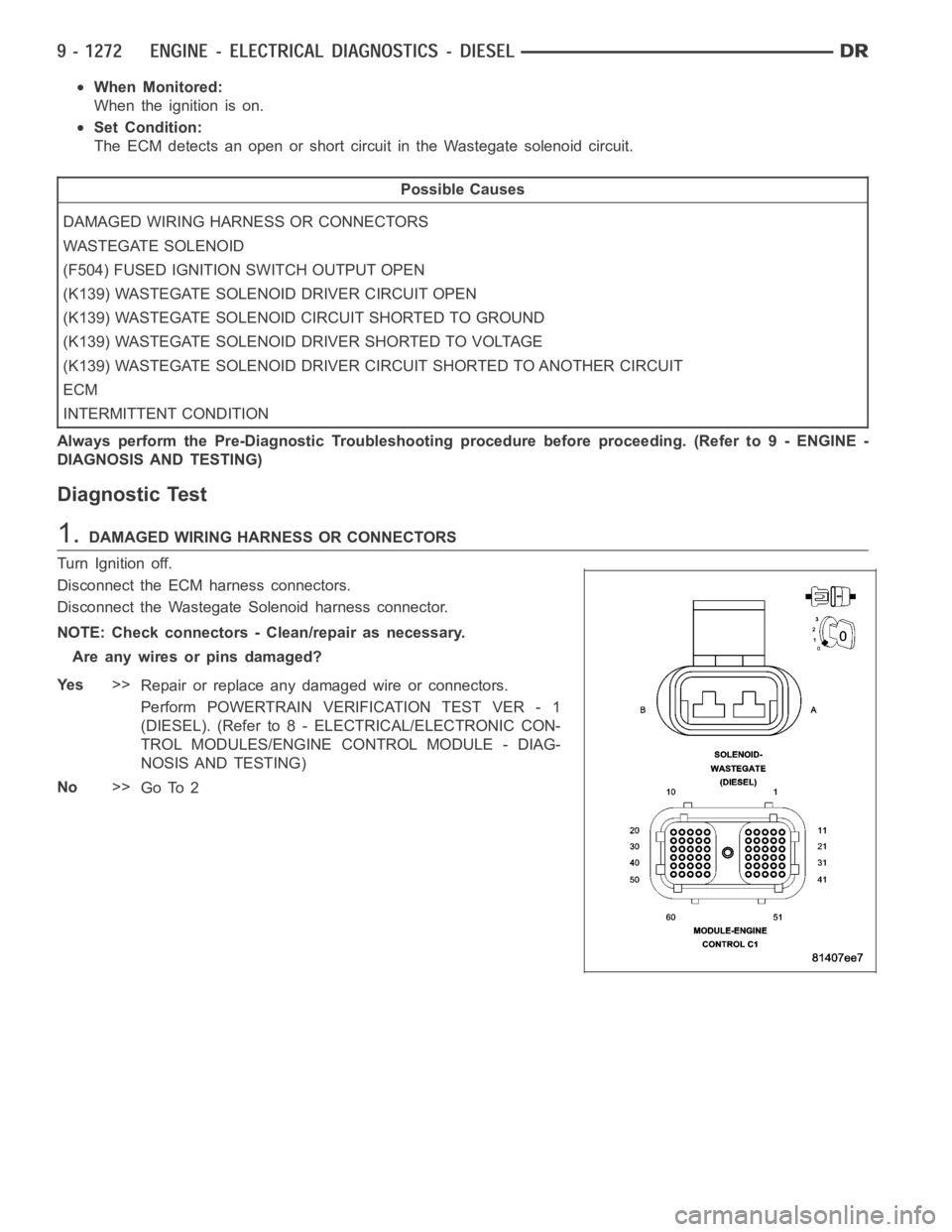
1.DAMAGED WIRING HARNESS OR CONNECTORS
Turn Ignition off.
Disconnect the ECM harness connectors.
Disconnect the Wastegate Solenoid harness connector.
NOTE: Check connectors - Clean/repair as necessary.
Areanywiresorpinsdamaged?
Ye s>>
Repair or replace any damaged wire or connectors.
Perform POWERTRAIN VERIFICATION TEST VER - 1
(DIESEL). (Refer to 8 - ELECTRICAL/ELECTRONIC CON-
TROL MODULES/ENGINE CONTROL MODULE - DIAG-
NOSIS AND TESTING)
No>>
Go To 2
Page 582 of 5267

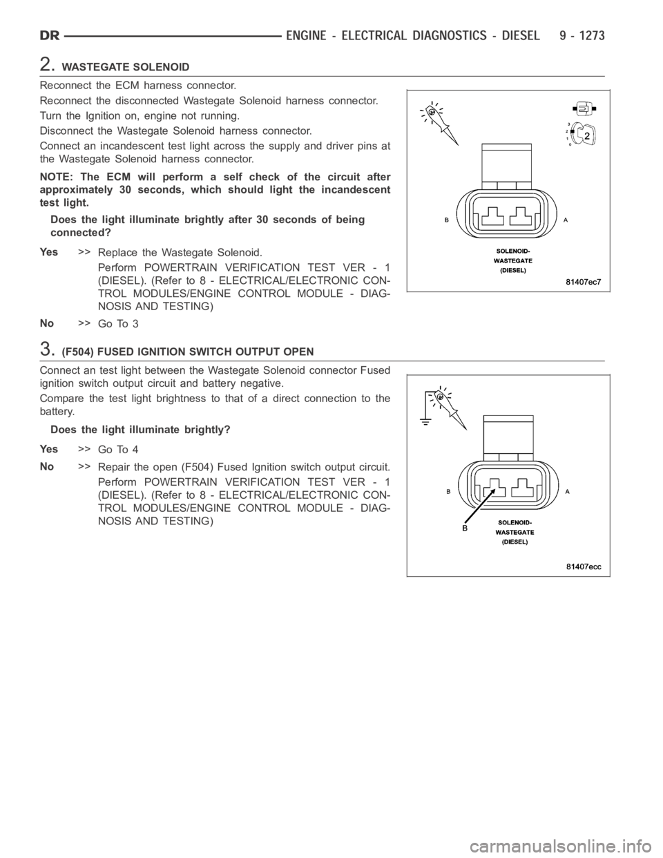
2.WASTEGATE SOLENOID
Reconnect the ECM harness connector.
Reconnect the disconnected Wastegate Solenoid harness connector.
Turn the Ignition on, engine not running.
Disconnect the Wastegate Solenoid harness connector.
Connect an incandescent test light across the supply and driver pins at
the Wastegate Solenoid harness connector.
NOTE: The ECM will perform a self check of the circuit after
approximately 30 seconds, which should light the incandescent
test light.
Does the light illuminate brightly after 30 seconds of being
connected?
Ye s>>
Replace the Wastegate Solenoid.
Perform POWERTRAIN VERIFICATION TEST VER - 1
(DIESEL). (Refer to 8 - ELECTRICAL/ELECTRONIC CON-
TROL MODULES/ENGINE CONTROL MODULE - DIAG-
NOSIS AND TESTING)
No>>
Go To 3
3.(F504) FUSED IGNITION SWITCH OUTPUT OPEN
Connect an test light between the Wastegate Solenoid connector Fused
ignition switch output circuit and battery negative.
Compare the test light brightness to that of a direct connection to the
battery.
Does the light illuminate brightly?
Ye s>>
Go To 4
No>>
Repair the open (F504) Fused Ignition switch output circuit.
Perform POWERTRAIN VERIFICATION TEST VER - 1
(DIESEL). (Refer to 8 - ELECTRICAL/ELECTRONIC CON-
TROL MODULES/ENGINE CONTROL MODULE - DIAG-
NOSIS AND TESTING)