Page 2845 of 5267

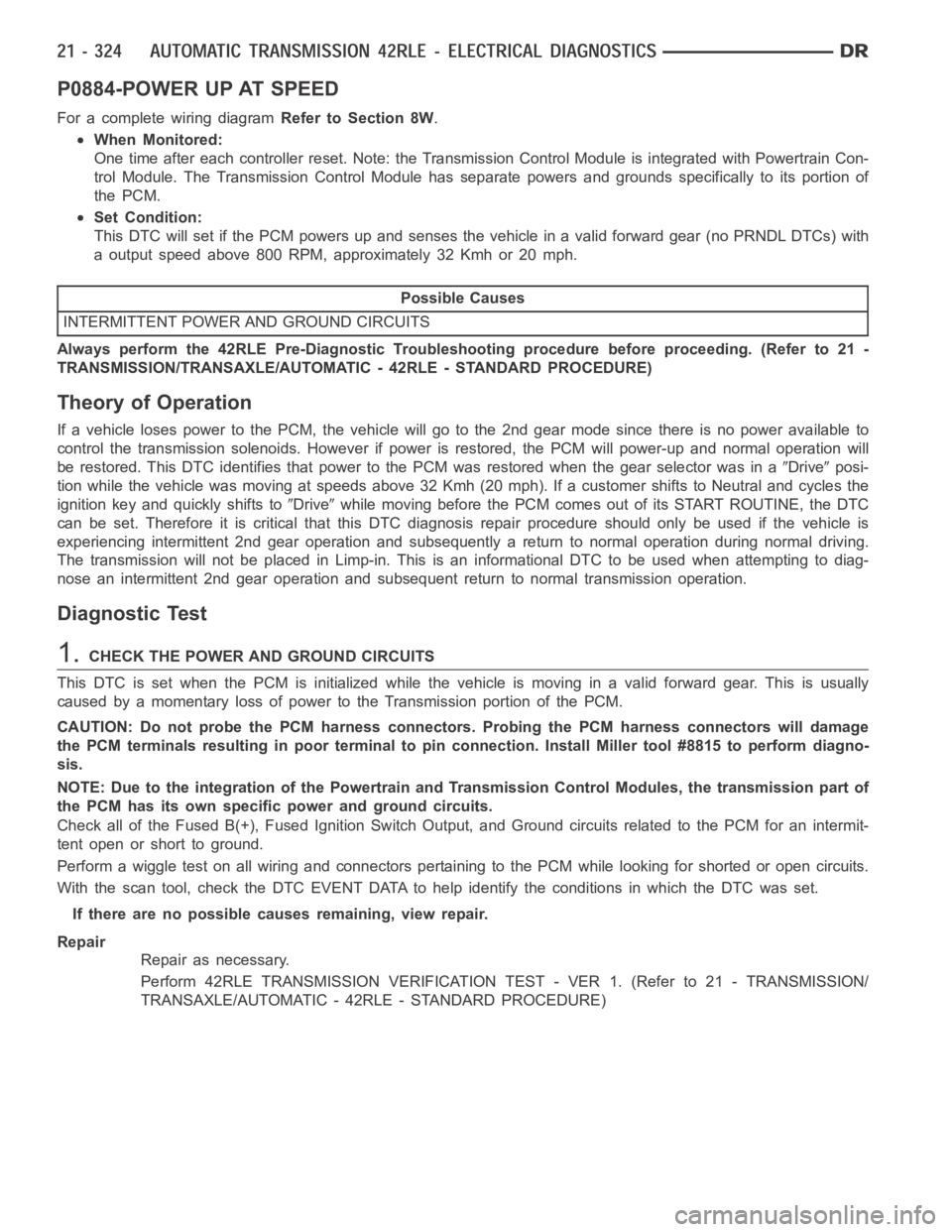
P0884-POWER UP AT SPEED
For a complete wiring diagramRefer to Section 8W.
When Monitored:
One time after each controller reset. Note: the Transmission Control Module is integrated with Powertrain Con-
trol Module. The Transmission Control Module has separate powers and grounds specifically to its portion of
the PCM.
Set Condition:
This DTC will set if the PCM powers up and senses the vehicle in a valid forward gear (no PRNDL DTCs) with
a output speed above 800 RPM, approximately 32 Kmh or 20 mph.
Possible Causes
INTERMITTENT POWER AND GROUND CIRCUITS
Always perform the 42RLE Pre-Diagnostic Troubleshooting procedure before proceeding. (Refer to 21 -
TRANSMISSION/TRANSAXLE/AUTOMATIC - 42RLE - STANDARD PROCEDURE)
Theory of Operation
If a vehicle loses power to the PCM, the vehicle will go to the 2nd gear mode since there is no power available to
control the transmission solenoids. However if power is restored, the PCMwill power-up and normal operation will
be restored. This DTC identifies that power to the PCM was restored when thegear selector was in a
Driveposi-
tion while the vehicle was moving at speeds above 32 Kmh (20 mph). If a customer shifts to Neutral and cycles the
ignition key and quickly shifts to
Drivewhile moving before the PCM comes out of its START ROUTINE, the DTC
can be set. Therefore it is critical that this DTC diagnosis repair procedure should only be used if the vehicle is
experiencing intermittent 2nd gear operation and subsequently a return to normal operation during normal driving.
The transmission will not be placed in Limp-in. This is an informational DTC to be used when attempting to diag-
nose an intermittent 2nd gear operation and subsequent return to normal transmission operation.
Diagnostic Test
1.CHECK THE POWER AND GROUND CIRCUITS
This DTC is set when the PCM is initialized while the vehicle is moving in a valid forward gear. This is usually
caused by a momentary loss of power to the Transmission portion of the PCM.
CAUTION: Do not probe the PCM harness connectors. Probing the PCM harness connectors will damage
the PCM terminals resulting in poor terminal to pin connection. Install Miller tool #8815 to perform diagno-
sis.
NOTE: Due to the integration of the Powertrain and Transmission Control Modules, the transmission part of
the PCM has its own specific power and ground circuits.
Check all of the Fused B(+), Fused Ignition Switch Output, and Ground circuits related to the PCM for an intermit-
tent open or short to ground.
Perform a wiggle test on all wiring and connectors pertaining to the PCM while looking for shorted or open circuits.
With the scan tool, check the DTC EVENT DATA to help identify the conditionsin which the DTC was set.
If there are no possible causes remaining, view repair.
Repair
Repair as necessary.
Perform 42RLE TRANSMISSION VERIFICATION TEST - VER 1. (Refer to 21 - TRANSMISSION/
TRANSAXLE/AUTOMATIC - 42RLE - STANDARD PROCEDURE)
Page 2846 of 5267
P0890-SWITCHED BATTERY
For a complete wiring diagramRefer to Section 8W.
Page 2850 of 5267

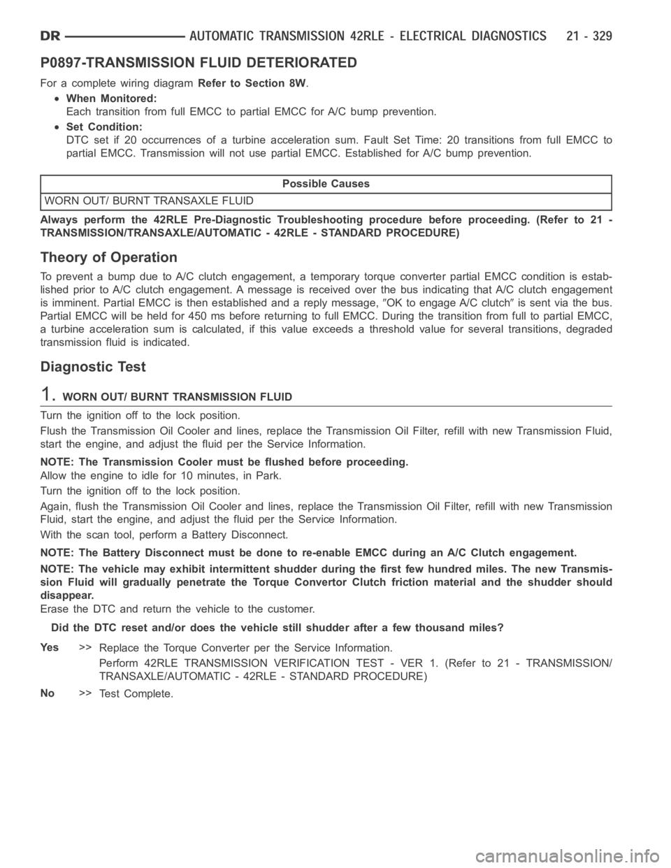
P0897-TRANSMISSION FLUID DETERIORATED
For a complete wiring diagramRefer to Section 8W.
When Monitored:
Each transition from full EMCC to partial EMCC for A/C bump prevention.
Set Condition:
DTC set if 20 occurrences of a turbine acceleration sum. Fault Set Time: 20 transitions from full EMCC to
partial EMCC. Transmission will not use partial EMCC. Established for A/Cbump prevention.
Possible Causes
WORN OUT/ BURNT TRANSAXLE FLUID
Always perform the 42RLE Pre-Diagnostic Troubleshooting procedure before proceeding. (Refer to 21 -
TRANSMISSION/TRANSAXLE/AUTOMATIC - 42RLE - STANDARD PROCEDURE)
Theory of Operation
To prevent a bump due to A/C clutch engagement, a temporary torque converter partial EMCC condition is estab-
lished prior to A/C clutch engagement. A message is received over the bus indicating that A/C clutch engagement
is imminent. Partial EMCC is then established and a reply message,
OK to engage A/C clutchis sent via the bus.
Partial EMCC will be held for 450 ms before returning to full EMCC. During the transition from full to partial EMCC,
a turbine acceleration sum is calculated, if this value exceeds a threshold value for several transitions, degraded
transmission fluid is indicated.
Diagnostic Test
1.WORN OUT/ BURNT TRANSMISSION FLUID
Turn the ignition off to the lock position.
Flush the Transmission Oil Cooler and lines, replace the Transmission OilFilter, refill with new Transmission Fluid,
start the engine, and adjust the fluid per the Service Information.
NOTE: The Transmission Cooler must be flushed before proceeding.
Allow the engine to idle for 10 minutes, in Park.
Turn the ignition off to the lock position.
Again, flush the Transmission Oil Cooler and lines, replace the Transmission Oil Filter, refill with new Transmission
Fluid, start the engine, and adjust the fluid per the Service Information.
With the scan tool, perform a Battery Disconnect.
NOTE: The Battery Disconnect must be done to re-enable EMCC during an A/C Clutch engagement.
NOTE: The vehicle may exhibit intermittent shudder during the first few hundred miles. The new Transmis-
sion Fluid will gradually penetrate the Torque Convertor Clutch frictionmaterial and the shudder should
disappear.
Erase the DTC and return the vehicle to the customer.
Did the DTC reset and/or does the vehicle still shudder after a few thousandmiles?
Ye s>>
Replace the Torque Converter per the Service Information.
Perform 42RLE TRANSMISSION VERIFICATION TEST - VER 1. (Refer to 21 - TRANSMISSION/
TRANSAXLE/AUTOMATIC - 42RLE - STANDARD PROCEDURE)
No>>
Te s t C o m p l e t e .
Page 2851 of 5267
P0932-LINE PRESSURE SENSOR CIRCUIT
For a complete wiring diagramRefer to Section 8W
Page 2854 of 5267
P0934-LINE PRESSURE SENSOR CIRCUIT LOW
For a complete wiring diagramRefer to Section 8W.
Page 2859 of 5267
P0935-LINE PRESSURE SENSOR CIRCUIT HIGH
For a complete wiring diagramRefer to Section 8W
Page 2864 of 5267

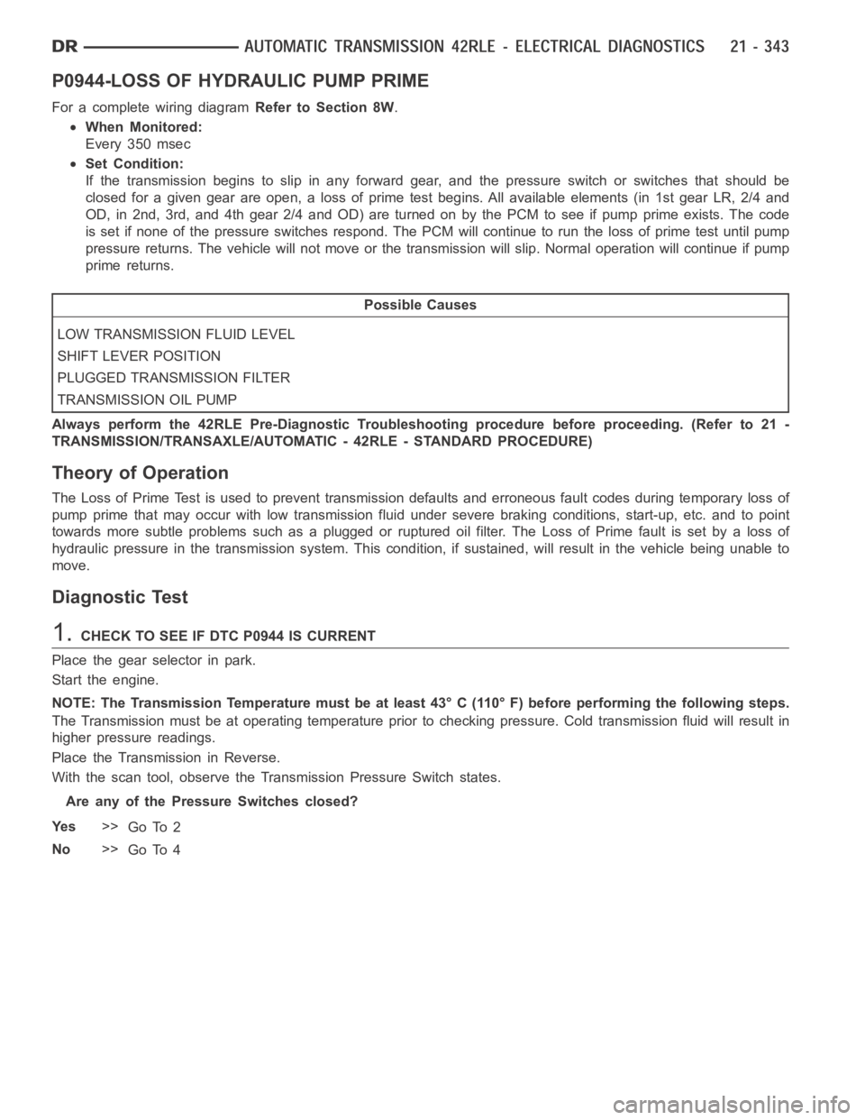
P0944-LOSS OF HYDRAULIC PUMP PRIME
For a complete wiring diagramRefer to Section 8W.
When Monitored:
Every 350 msec
Set Condition:
If the transmission begins to slip in any forward gear, and the pressure switch or switches that should be
closed for a given gear are open, a loss of prime test begins. All available elements (in 1st gear LR, 2/4 and
OD, in 2nd, 3rd, and 4th gear 2/4 and OD) are turned on by the PCM to see if pump prime exists. The code
is set if none of the pressure switches respond. The PCM will continue to runthe loss of prime test until pump
pressure returns. The vehicle will not move or the transmission will slip.Normal operation will continue if pump
prime returns.
Possible Causes
LOW TRANSMISSION FLUID LEVEL
SHIFT LEVER POSITION
PLUGGED TRANSMISSION FILTER
TRANSMISSION OIL PUMP
Always perform the 42RLE Pre-Diagnostic Troubleshooting procedure before proceeding. (Refer to 21 -
TRANSMISSION/TRANSAXLE/AUTOMATIC - 42RLE - STANDARD PROCEDURE)
Theory of Operation
The Loss of Prime Test is used to prevent transmission defaults and erroneous fault codes during temporary loss of
pump prime that may occur with low transmission fluid under severe brakingconditions, start-up, etc. and to point
towards more subtle problems such as a plugged or ruptured oil filter. The Loss of Prime fault is set by a loss of
hydraulic pressure in the transmission system. This condition, if sustained, will result in the vehicle being unable to
move.
Diagnostic Test
1.CHECK TO SEE IF DTC P0944 IS CURRENT
Place the gear selector in park.
Start the engine.
NOTE: The Transmission Temperature must be at least 43° C (110° F) before performing the following steps.
The Transmission must be at operating temperature prior to checking pressure. Cold transmission fluid will result in
higher pressure readings.
Place the Transmission in Reverse.
With the scan tool, observe the Transmission Pressure Switch states.
Are any of the Pressure Switches closed?
Ye s>>
Go To 2
No>>
Go To 4
Page 2866 of 5267

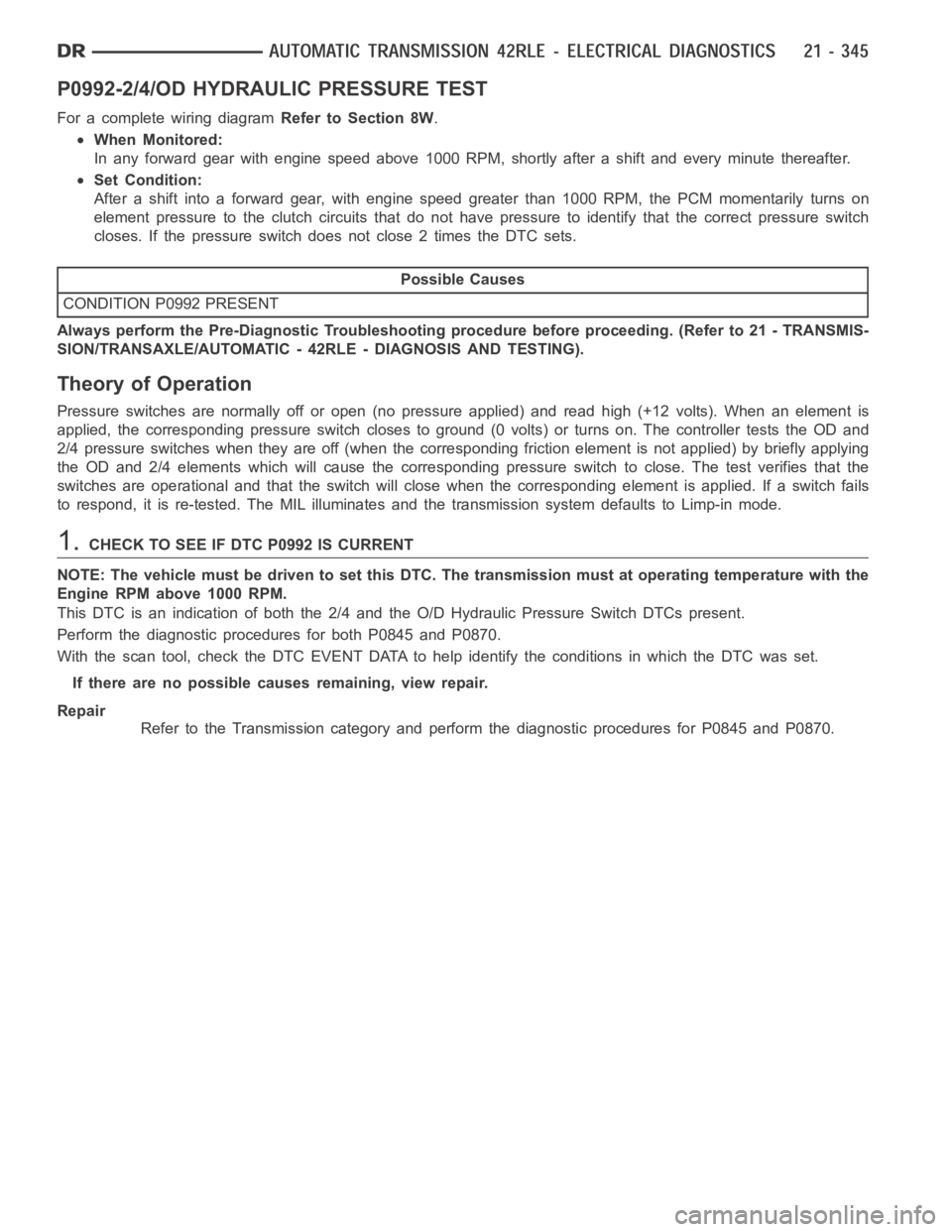
P0992-2/4/OD HYDRAULIC PRESSURE TEST
For a complete wiring diagramRefer to Section 8W.
When Monitored:
In any forward gear with engine speed above 1000 RPM, shortly after a shift and every minute thereafter.
Set Condition:
After a shift into a forward gear, with engine speed greater than 1000 RPM, the PCM momentarily turns on
element pressure to the clutch circuits that do not have pressure to identify that the correct pressure switch
closes. If the pressure switch does not close 2 times the DTC sets.
Possible Causes
CONDITION P0992 PRESENT
Always perform the Pre-Diagnostic Troubleshooting procedure before proceeding. (Refer to 21 - TRANSMIS-
SION/TRANSAXLE/AUTOMATIC - 42RLE - DIAGNOSIS AND TESTING).
Theory of Operation
Pressure switches are normally off or open (no pressure applied) and read high (+12 volts). When an element is
applied, the corresponding pressure switch closes to ground (0 volts) or turns on. The controller tests the OD and
2/4 pressure switches when they are off (when the corresponding friction element is not applied) by briefly applying
the OD and 2/4 elements which will cause the corresponding pressure switchto close. The test verifies that the
switches are operational and that the switch will close when the corresponding element is applied. If a switch fails
to respond, it is re-tested. The MIL illuminates and the transmission system defaults to Limp-in mode.
1.CHECK TO SEE IF DTC P0992 IS CURRENT
NOTE: The vehicle must be driven to set this DTC. The transmission must at operating temperature with the
Engine RPM above 1000 RPM.
This DTC is an indication of both the 2/4 and the O/D Hydraulic Pressure Switch DTCs present.
Perform the diagnostic procedures for both P0845 and P0870.
With the scan tool, check the DTC EVENT DATA to help identify the conditionsin which the DTC was set.
If there are no possible causes remaining, view repair.
Repair
Refer to the Transmission category and perform the diagnostic proceduresfor P0845 and P0870.