Page 2902 of 5267
U0002 CAN C BUS OFF PERFORMANCE
For a complete wiring diagramRefer to Section 8W.
Page 2904 of 5267
U0121 LOST COMMUNICATION WITH ABS
For a complete wiring diagramRefer to Section 8W.
Page 2906 of 5267
U0141 LOST COMMUNICATION WITH FCM
For a complete wiring diagramRefer to Section 8W.
Page 2908 of 5267

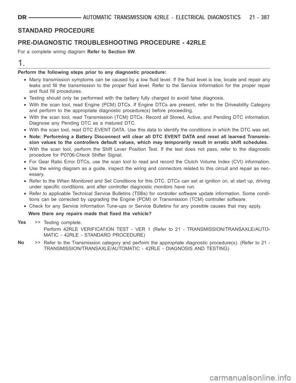
STANDARD PROCEDURE
PRE-DIAGNOSTIC TROUBLESHOOTING PROCEDURE - 42RLE
For a complete wiring diagramRefer to Section 8W.
1.
Perform the following steps prior to any diagnostic procedure:
Many transmission symptoms can be caused by a low fluid level. If the fluid level is low, locate and repair any
leaks and fill the transmission to the proper fluid level. Refer to the Service Information for the proper repair
and fluid fill procedures.
Testing should only be performed with the battery fully charged to avoid false diagnosis.
With the scan tool, read Engine (PCM) DTCs. If Engine DTCs are present, refer to the Driveability Category
and perform to the appropriate diagnostic procedure(s) before proceeding.
With the scan tool, read Transmission (TCM) DTCs. Record all Stored, Active, and Pending DTC information.
Diagnose any Pending DTC as a matured DTC.
With the scan tool, read DTC EVENT DATA.Use this data to identify the conditions in which the DTC was set.
Note: Performing a Battery Disconnect will clear all DTC EVENT DATA and reset all learned Transmis-
sion values to the controllers default values, which may temporarily result in erratic shift schedules.
With the scan tool, perform the Shift Lever Position Test. If the test does not pass, refer to the diagnostic
procedure for P0706-Check Shifter Signal.
For Gear Ratio Error DTCs, use the scan tool to read and record the Clutch Volume Index (CVI) information.
Use the wiring diagram as a guide, inspect the wiring and connectors related to this circuit and repair as nec-
essary.
Refer to the When Monitored and Set Conditions for this DTC. DTCs can set at ignition on, at start up, driving
under specific conditions, and after controller diagnostic monitors haverun.
Refer to applicable Technical Service Bulletins (TSBs) for controller software update information. Some condi-
tions can be corrected by upgrading the Engine (PCM) or Transmission (TCM)controller software.
Check for any Service Information Tune-ups or Service Bulletins for any possible causes that may apply.
Were there any repairs made that fixed the vehicle?
Ye s>>
Testing complete.
Perform 42RLE VERIFICATION TEST - VER1(Referto21-TRANSMISSION/TRANSAXLE/AUTO-
MATIC - 42RLE - STANDARD PROCEDURE)
No>>
Refer to the Transmission category and perform the appropriate diagnostic procedure(s). (Refer to 21 -
TRANSMISSION/TRANSAXLE/AUTOMATIC - 42RLE - DIAGNOSIS AND TESTING)
Page 2910 of 5267

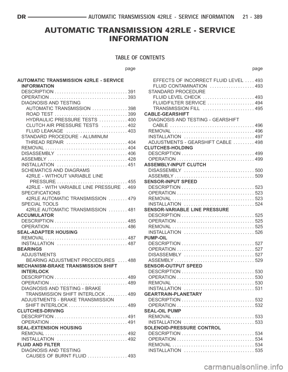
page page
AUTOMATIC TRANSMISSION 42RLE - SERVICE
INFORMATION
DESCRIPTION ............................... 391
OPERATION ................................. 393
DIAGNOSIS AND TESTING
AUTOMATIC TRANSMISSION ............... 398
ROAD TEST ............................... 399
HYDRAULIC PRESSURE TESTS............ 400
CLUTCH AIR PRESSURE TESTS........... 402
FLUID LEAKAGE.......................... 403
STANDARD PROCEDURE - ALUMINUM
THREAD REPAIR .......................... 404
REMOVAL ................................... 404
DISASSEMBLY .............................. 406
ASSEMBLY .................................. 428
INSTALLATION .............................. 451
SCHEMATICS AND DIAGRAMS
42RLE - WITHOUT VARIABLE LINE
PRESSURE............................... 455
42RLE - WITH VARIABLE LINE PRESSURE . . 469
SPECIFICATIONS
42RLE AUTOMATIC TRANSMISSION ........ 479
SPECIAL TOOLS
42RLE AUTOMATIC TRANSMISSION ........ 481
ACCUMULATOR
DESCRIPTION ............................... 485
OPERATION ................................. 486
SEAL-ADAPTER HOUSING
REMOVAL ................................... 487
INSTALLATION .............................. 487
BEARINGS
ADJUSTMENTS
BEARING ADJUSTMENT PROCEDURES.... 488
MECHANISM-BRAKE TRANSMISSION SHIFT
INTERLOCK
DESCRIPTION ............................... 489
OPERATION ................................. 489
DIAGNOSIS AND TESTING - BRAKE
TRANSMISSION SHIFT INTERLOCK ......... 489
ADJUSTMENTS - BRAKE TRANSMISSION
SHIFT INTERLOCK ......................... 489
CLUTCHES-DRIVING
DESCRIPTION ............................... 491
OPERATION ................................. 491
SEAL-EXTENSION HOUSING
REMOVAL ................................... 492
INSTALLATION .............................. 492
FLUID AND FILTER
DIAGNOSIS AND TESTING
CAUSES OF BURNT FLUID ................. 493EFFECTS OF INCORRECT FLUID LEVEL . . . . 493
FLUID CONTAMINATION ................... 493
STANDARD PROCEDURE
FLUID LEVEL CHECK...................... 493
FLUID/FILTER SERVICE .................... 494
TRANSMISSION FILL ...................... 495
CABLE-GEARSHIFT
DIAGNOSIS AND TESTING - GEARSHIFT
CABLE .................................... 496
REMOVAL ................................... 496
INSTALLATION .............................. 497
ADJUSTMENTS - GEARSHIFT CABLE ......... 498
CLUTCHES-HOLDING
DESCRIPTION ............................... 499
OPERATION ................................. 499
ASSEMBLY-INPUT CLUTCH
DISASSEMBLY .............................. 500
ASSEMBLY .................................. 509
SENSOR-INPUT SPEED
DESCRIPTION ............................... 523
OPERATION ................................. 523
REMOVAL ................................... 523
INSTALLATION .............................. 524
SENSOR-VARIABLE LINE PRESSURE
DESCRIPTION ............................... 525
OPERATION ................................. 525
REMOVAL ................................... 525
INSTALLATION .............................. 526
PUMP-OIL
DESCRIPTION ............................... 527
OPERATION ................................. 527
DISASSEMBLY .............................. 527
ASSEMBLY .................................. 529
SENSOR-OUTPUT SPEED
DESCRIPTION ............................... 530
OPERATION ................................. 530
REMOVAL ................................... 530
INSTALLATION .............................. 531
GEARTRAIN-PLANETARY
DESCRIPTION ............................... 532
OPERATION ................................. 532
SEAL-OIL PUMP
REMOVAL ................................... 533
INSTALLATION .............................. 533
SOLENOID-PRESSURE CONTROL
DESCRIPTION ............................... 534
OPERATION ................................. 534
REMOVAL ................................... 534
INSTALLATION .............................. 535
Page 2976 of 5267
SCHEMATICS AND DIAGRAMS
42RLE - WITHOUT VARIABLE LINE PRESSURE
Page 3079 of 5267
The valves contained within the valve body (1) include the following :
Regulator valve (8)
Solenoid switch valve (7)
Manual valve (5)
Converter clutch switch valve (6)
Converter clutch control valve (4)
Torque converter regulator valve (2)
Low/Reverse switch valve (3)
In addition, the valve body also contains the thermal valve, #2, 3, 4 & 5 check balls and the 2/4 accumulator assem-
bly.
OPERATION
NOTE: (Refer to 21 - TRANSMISSION/AUTOMATIC - 42RLE - SCHEMATICS AND DIAGRAMS) for a visual aid
in determining valve location, operation and design.
Valve Body - Exploded
1-VALVEBODY
2 - T / C R E G U L AT O R VA LV E
3-L/RSWITCHVALVE
4 - CONVERTER CLUTCH CONTROL VALVE
5 - MANUAL VALVE
6 - CONVERTER CLUTCH SWITCH VALVE
7 - SOLENOID SWITCH VALVE
8 - REGULATOR VALVE
Page 3103 of 5267

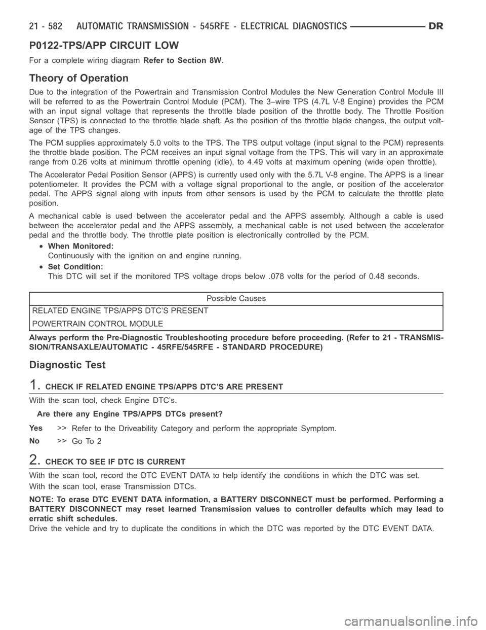
P0122-TPS/APP CIRCUIT LOW
For a complete wiring diagramRefer to Section 8W.
Theory of Operation
Due to the integration of the Powertrain and Transmission Control Modulesthe New Generation Control Module III
will be referred to as the Powertrain Control Module (PCM). The 3–wire TPS (4.7L V-8 Engine) provides the PCM
with an input signal voltage that represents the throttle blade position of the throttle body. The Throttle Position
Sensor (TPS) is connected to the throttle blade shaft. As the position of the throttle blade changes, the output volt-
age of the TPS changes.
The PCM supplies approximately 5.0 volts to the TPS. The TPS output voltage(input signal to the PCM) represents
the throttle blade position. The PCM receives an input signal voltage fromthe TPS. This will vary in an approximate
range from 0.26 volts at minimum throttle opening (idle), to 4.49 volts at maximum opening (wide open throttle).
The Accelerator Pedal Position Sensor (APPS) is currently used only with the 5.7L V-8 engine. The APPS is a linear
potentiometer. It provides the PCM with a voltage signal proportional to the angle, or position of the accelerator
pedal. The APPS signal along with inputs from other sensors is used by the PCM to calculate the throttle plate
position.
A mechanical cable is used between the accelerator pedal and the APPS assembly. Although a cable is used
between the accelerator pedal and the APPS assembly, a mechanical cable isnot used between the accelerator
pedal and the throttle body. The throttle plate position is electronically controlled by the PCM.
When Monitored:
Continuously with the ignition on and engine running.
Set Condition:
This DTC will set if the monitored TPS voltage drops below .078 volts for theperiod of 0.48 seconds.
Possible Causes
RELATED ENGINE TPS/APPS DTC’S PRESENT
POWERTRAIN CONTROL MODULE
Always perform the Pre-Diagnostic Troubleshooting procedure before proceeding. (Refer to 21 - TRANSMIS-
SION/TRANSAXLE/AUTOMATIC - 45RFE/545RFE - STANDARD PROCEDURE)
Diagnostic Test
1.CHECK IF RELATED ENGINE TPS/APPS DTC’S ARE PRESENT
With the scan tool, check Engine DTC’s.
Are there any Engine TPS/APPS DTCs present?
Ye s>>
Refer to the Driveability Category and perform the appropriate Symptom.
No>>
Go To 2
2.CHECK TO SEE IF DTC IS CURRENT
With the scan tool, record the DTC EVENT DATA to help identify the conditionsinwhichtheDTCwasset.
With the scan tool, erase Transmission DTCs.
NOTE: To erase DTC EVENT DATA information, a BATTERY DISCONNECT must be performed. Performing a
BATTERY DISCONNECT may reset learned Transmission values to controller defaults which may lead to
erratic shift schedules.
Drive the vehicle and try to duplicate the conditions in which the DTC was reported by the DTC EVENT DATA.