Page 2777 of 5267

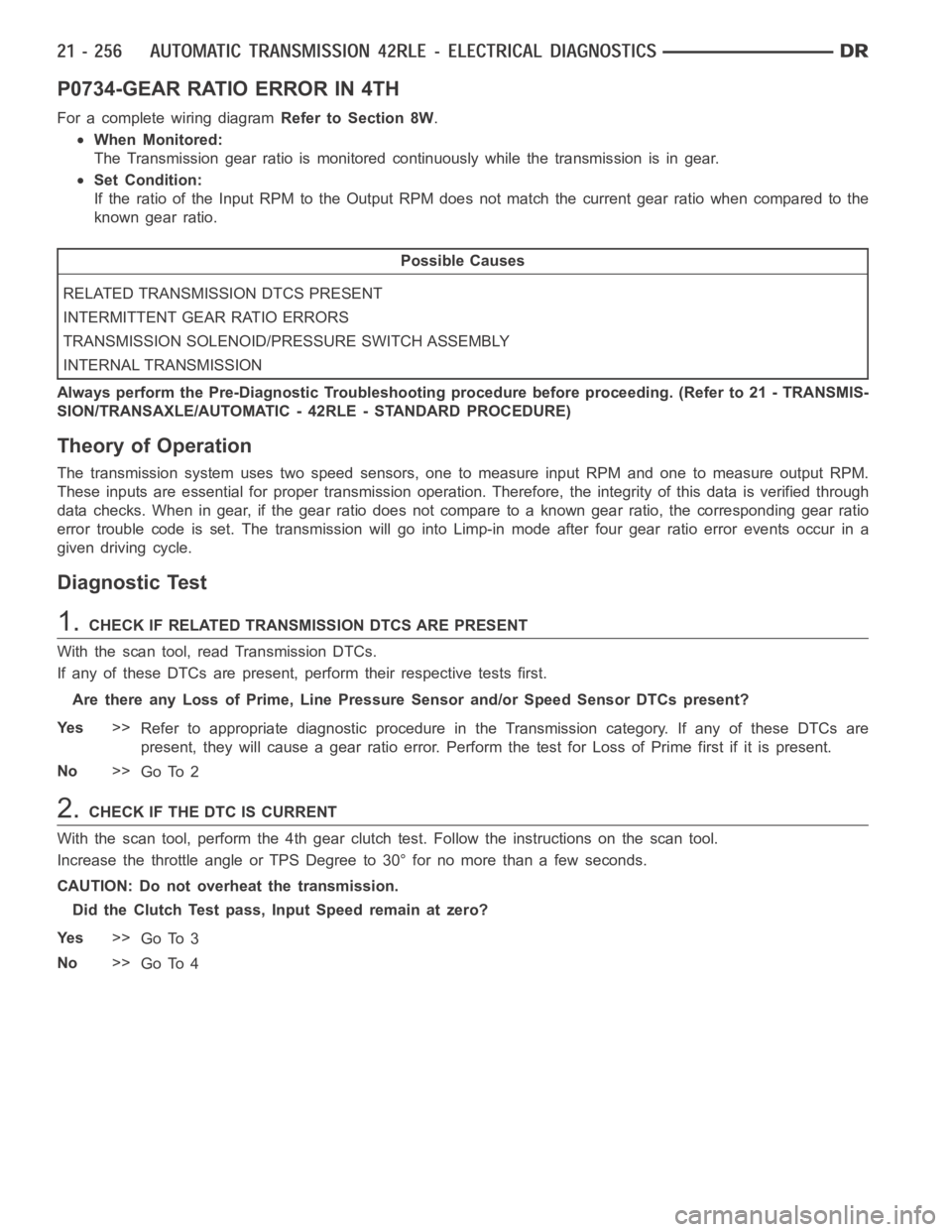
P0734-GEAR RATIO ERROR IN 4TH
For a complete wiring diagramRefer to Section 8W.
When Monitored:
The Transmission gear ratio is monitored continuously while the transmission is in gear.
Set Condition:
If the ratio of the Input RPM to the Output RPM does not match the current gearratio when compared to the
known gear ratio.
Possible Causes
RELATED TRANSMISSION DTCS PRESENT
INTERMITTENT GEAR RATIO ERRORS
TRANSMISSION SOLENOID/PRESSURE SWITCH ASSEMBLY
INTERNAL TRANSMISSION
Always perform the Pre-Diagnostic Troubleshooting procedure before proceeding. (Refer to 21 - TRANSMIS-
SION/TRANSAXLE/AUTOMATIC - 42RLE - STANDARD PROCEDURE)
Theory of Operation
The transmission system uses two speed sensors, one to measure input RPM and one to measure output RPM.
These inputs are essential for proper transmission operation. Therefore, the integrity of this data is verified through
data checks. When in gear, if the gear ratio does not compare to a known gear ratio, the corresponding gear ratio
error trouble code is set. The transmission will go into Limp-in mode afterfour gear ratio error events occur in a
given driving cycle.
Diagnostic Test
1.CHECK IF RELATED TRANSMISSION DTCS ARE PRESENT
With the scan tool, read Transmission DTCs.
If any of these DTCs are present, perform their respective tests first.
Are there any Loss of Prime, Line Pressure Sensor and/or Speed Sensor DTCs present?
Ye s>>
Refer to appropriate diagnostic procedure in the Transmission category.If any of these DTCs are
present, they will cause a gear ratio error. Perform the test for Loss of Primefirstifitispresent.
No>>
Go To 2
2.CHECK IF THE DTC IS CURRENT
With the scan tool, perform the 4th gear clutch test. Follow the instructions on the scan tool.
Increase the throttle angle or TPS Degree to 30° for no more than a few seconds.
CAUTION: Do not overheat the transmission.
Did the Clutch Test pass, Input Speed remain at zero?
Ye s>>
Go To 3
No>>
Go To 4
Page 2779 of 5267

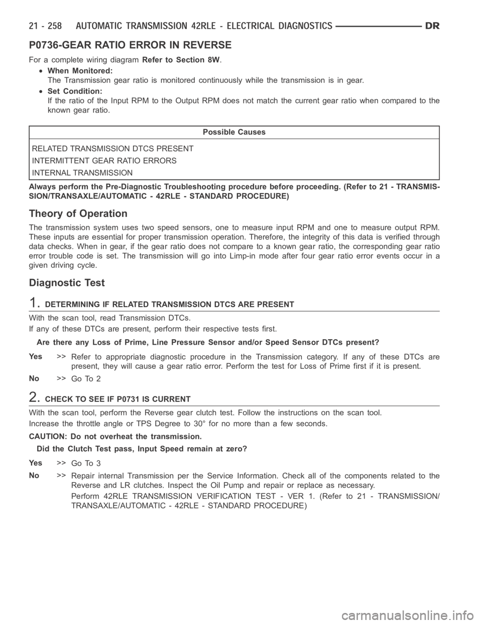
P0736-GEAR RATIO ERROR IN REVERSE
For a complete wiring diagramRefer to Section 8W.
When Monitored:
The Transmission gear ratio is monitored continuously while the transmission is in gear.
Set Condition:
If the ratio of the Input RPM to the Output RPM does not match the current gearratio when compared to the
known gear ratio.
Possible Causes
RELATED TRANSMISSION DTCS PRESENT
INTERMITTENT GEAR RATIO ERRORS
INTERNAL TRANSMISSION
Always perform the Pre-Diagnostic Troubleshooting procedure before proceeding. (Refer to 21 - TRANSMIS-
SION/TRANSAXLE/AUTOMATIC - 42RLE - STANDARD PROCEDURE)
Theory of Operation
The transmission system uses two speed sensors, one to measure input RPM and one to measure output RPM.
These inputs are essential for proper transmission operation. Therefore, the integrity of this data is verified through
data checks. When in gear, if the gear ratio does not compare to a known gear ratio, the corresponding gear ratio
error trouble code is set. The transmission will go into Limp-in mode afterfour gear ratio error events occur in a
given driving cycle.
Diagnostic Test
1.DETERMINING IF RELATED TRANSMISSION DTCS ARE PRESENT
With the scan tool, read Transmission DTCs.
If any of these DTCs are present, perform their respective tests first.
Are there any Loss of Prime, Line Pressure Sensor and/or Speed Sensor DTCs present?
Ye s>>
Refer to appropriate diagnostic procedure in the Transmission category.If any of these DTCs are
present, they will cause a gear ratio error. Perform the test for Loss of Primefirstifitispresent.
No>>
Go To 2
2.CHECK TO SEE IF P0731 IS CURRENT
With the scan tool, perform the Reverse gear clutch test. Follow the instructions on the scan tool.
Increase the throttle angle or TPS Degree to 30° for no more than a few seconds.
CAUTION: Do not overheat the transmission.
Did the Clutch Test pass, Input Speed remain at zero?
Ye s>>
Go To 3
No>>
Repair internal Transmission per the Service Information. Check all of the components related to the
Reverse and LR clutches. Inspect the Oil Pump and repair or replace as necessary.
Perform 42RLE TRANSMISSION VERIFICATION TEST - VER 1. (Refer to 21 - TRANSMISSION/
TRANSAXLE/AUTOMATIC - 42RLE - STANDARD PROCEDURE)
Page 2781 of 5267

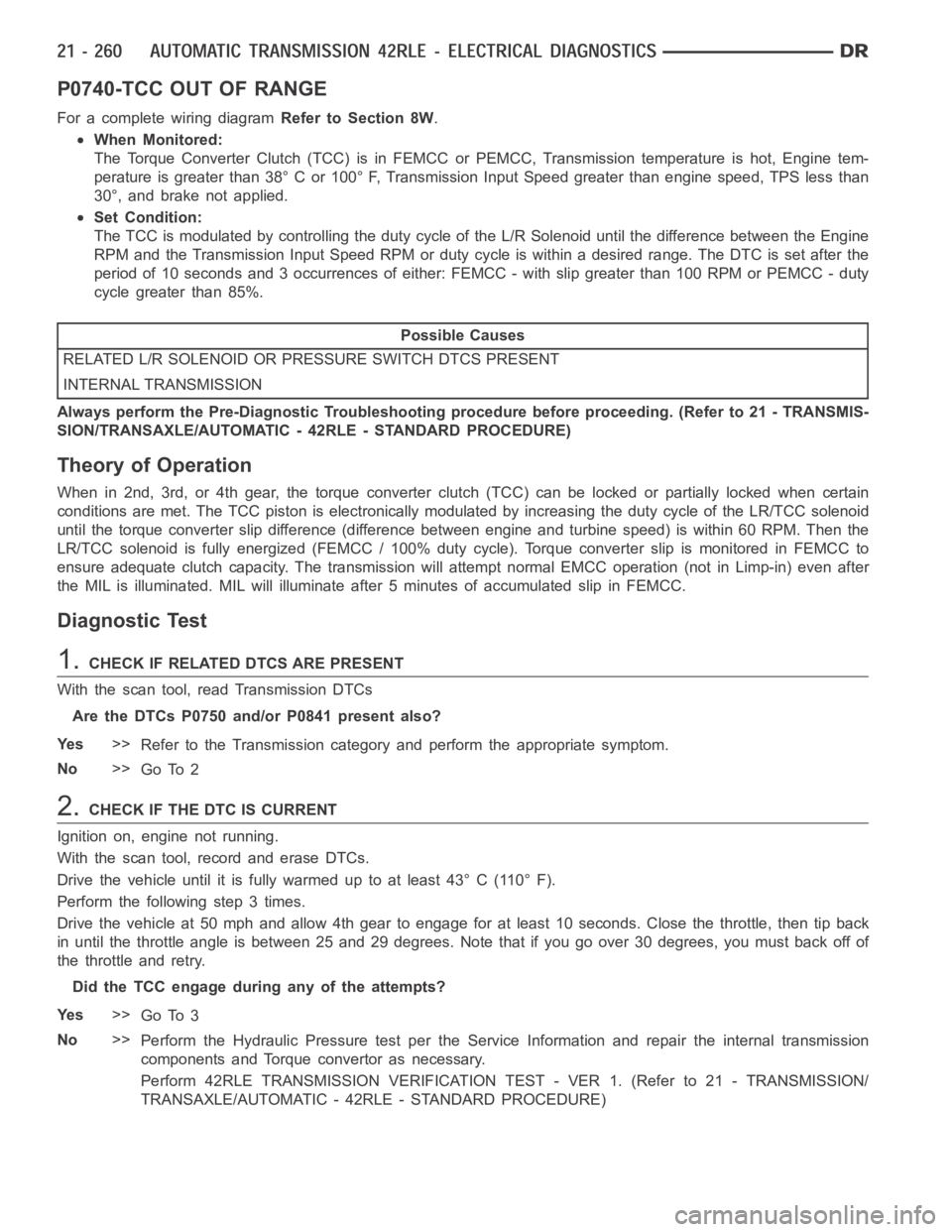
P0740-TCC OUT OF RANGE
For a complete wiring diagramRefer to Section 8W.
When Monitored:
The Torque Converter Clutch (TCC) is in FEMCC or PEMCC, Transmission temperature is hot, Engine tem-
perature is greater than 38° C or 100° F, Transmission Input Speed greater than engine speed, TPS less than
30°, and brake not applied.
Set Condition:
The TCC is modulated by controlling the duty cycle of the L/R Solenoid untilthe difference between the Engine
RPM and the Transmission Input Speed RPM or duty cycle is within a desired range. The DTC is set after the
period of 10 seconds and 3 occurrences of either: FEMCC - with slip greater than 100 RPM or PEMCC - duty
cycle greater than 85%.
Possible Causes
RELATED L/R SOLENOID OR PRESSURE SWITCH DTCS PRESENT
INTERNAL TRANSMISSION
Always perform the Pre-Diagnostic Troubleshooting procedure before proceeding. (Refer to 21 - TRANSMIS-
SION/TRANSAXLE/AUTOMATIC - 42RLE - STANDARD PROCEDURE)
Theory of Operation
When in 2nd, 3rd, or 4th gear, the torque converter clutch (TCC) can be locked or partially locked when certain
conditions are met. The TCC piston is electronically modulated by increasing the duty cycle of the LR/TCC solenoid
until the torque converter slip difference (difference between engine and turbine speed) is within 60 RPM. Then the
LR/TCC solenoid is fully energized (FEMCC / 100% duty cycle). Torque converter slip is monitored in FEMCC to
ensure adequate clutch capacity. The transmission will attempt normal EMCC operation (not in Limp-in) even after
the MIL is illuminated. MIL will illuminate after 5 minutes of accumulatedslip in FEMCC.
Diagnostic Test
1.CHECK IF RELATED DTCS ARE PRESENT
With the scan tool, read Transmission DTCs
Are the DTCs P0750 and/or P0841 present also?
Ye s>>
Refer to the Transmission category and perform the appropriate symptom.
No>>
Go To 2
2.CHECK IF THE DTC IS CURRENT
Ignition on, engine not running.
With the scan tool, record and erase DTCs.
Drive the vehicle until it is fully warmed up to at least 43° C (110° F).
Perform the following step 3 times.
Drive the vehicle at 50 mph and allow 4th gear to engage for at least 10 seconds. Close the throttle, then tip back
in until the throttle angle is between 25 and 29 degrees. Note that if you go over 30 degrees, you must back off of
the throttle and retry.
Did the TCC engage during any of the attempts?
Ye s>>
Go To 3
No>>
Perform the Hydraulic Pressure test per the Service Information and repair the internal transmission
components and Torque convertor as necessary.
Perform 42RLE TRANSMISSION VERIFICATION TEST - VER 1. (Refer to 21 - TRANSMISSION/
TRANSAXLE/AUTOMATIC - 42RLE - STANDARD PROCEDURE)
Page 2783 of 5267
P0750-LR SOLENOID CIRCUIT
For a complete wiring diagramRefer to Section 8W.
Page 2787 of 5267
P0755-2/4 SOLENOID CIRCUIT
For a complete wiring diagramRefer to Section 8W.
Page 2791 of 5267
P0760-OD SOLENOID CIRCUIT
For a complete wiring diagramRefer to Section 8W.
Page 2795 of 5267
P0765-UD SOLENOID CIRCUIT
For a complete wiring diagramRefer to Section 8W.
Page 2800 of 5267
P0841-LR PRESSURE SWITCH RATIONALITY
For a complete wiring diagramRefer to Section 8W.