Page 1462 of 5267
*BRAKE SWITCH SENSE STATUS DOES NOT CHANGE ON THE SCAN TOOL
For a complete wiring diagramRefer to Section 8W.
Page 1466 of 5267
*CANNOT SHIFT INTO REVERSE
For a complete wiring diagramRefer to Section 8W.
Page 1468 of 5267
*CHECKING A/C SYSTEM OPERATION WITH NO DTCS
For a complete wiring diagramRefer to Section 8W.
Page 1472 of 5267
*CHECKING CHARGING SYSTEM OPERATION WITH NO DTCS
For a complete wiring diagramRefer to Section 8W.
Page 1476 of 5267
*CHECKING RADIATOR FAN OPERATION
For a complete wiring diagramRefer to Section 8W.
Page 1478 of 5267
*CHECKING THE PCM POWER AND GROUNDS
For a complete wiring diagramRefer to Section 8W.
Page 1481 of 5267

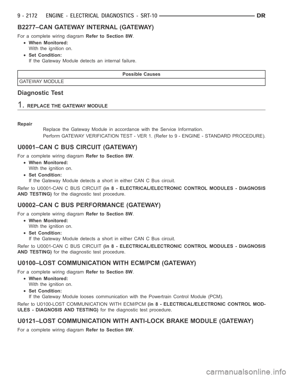
B2277–CAN GATEWAY INTERNAL (GATEWAY)
For a complete wiring diagramRefer to Section 8W.
When Monitored:
With the ignition on.
Set Condition:
If the Gateway Module detects an internal failure.
Possible Causes
GATEWAY MODULE
Diagnostic Test
1.REPLACE THE GATEWAY MODULE
Repair
Replace the Gateway Module in accordance with the Service Information.
Perform GATEWAY VERIFICATION TEST - VER 1. (Refer to 9 - ENGINE - STANDARD PROCEDURE).
U0001–CAN C BUS CIRCUIT (GATEWAY)
For a complete wiring diagramRefer to Section 8W.
When Monitored:
With the ignition on.
Set Condition:
If the Gateway Module detects a short in either CAN C Bus circuit.
Refer to U0001-CAN C BUS CIRCUIT(in 8 - ELECTRICAL/ELECTRONIC CONTROL MODULES - DIAGNOSIS
AND TESTING)for the diagnostic test procedure.
U0002–CAN C BUS PERFORMANCE (GATEWAY)
For a complete wiring diagramRefer to Section 8W.
When Monitored:
With the ignition on.
Set Condition:
If the Gateway Module detects a short in either CAN C Bus circuit.
Refer to U0001-CAN C BUS CIRCUIT(in 8 - ELECTRICAL/ELECTRONIC CONTROL MODULES - DIAGNOSIS
AND TESTING)for the diagnostic test procedure.
U0100–LOST COMMUNICATION WITH ECM/PCM (GATEWAY)
For a complete wiring diagramRefer to Section 8W.
When Monitored:
With the ignition on.
Set Condition:
If the Gateway Module looses communication with the Powertrain Control Module (PCM).
Refer to U0100-LOST COMMUNICATION WITH ECM/PCM(in 8 - ELECTRICAL/ELECTRONIC CONTROL MOD-
ULES - DIAGNOSIS AND TESTING)for the diagnostic test procedure.
U0121–LOST COMMUNICATION WITH ANTI-LOCK BRAKE MODULE (GATEWAY)
For a complete wiring diagramRefer to Section 8W.
Page 1482 of 5267

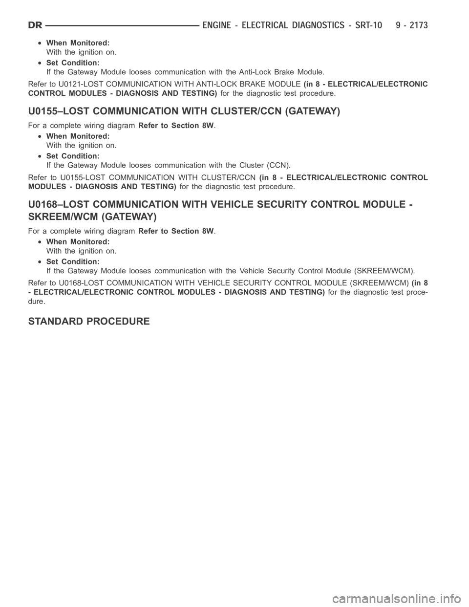
When Monitored:
With the ignition on.
Set Condition:
If the Gateway Module looses communication with the Anti-Lock Brake Module.
Refer to U0121-LOST COMMUNICATION WITH ANTI-LOCK BRAKE MODULE(in 8 - ELECTRICAL/ELECTRONIC
CONTROL MODULES - DIAGNOSIS AND TESTING)for the diagnostic test procedure.
U0155–LOST COMMUNICATION WITH CLUSTER/CCN (GATEWAY)
For a complete wiring diagramRefer to Section 8W.
When Monitored:
With the ignition on.
Set Condition:
If the Gateway Module looses communication with the Cluster (CCN).
Refer to U0155-LOST COMMUNICATION WITH CLUSTER/CCN(in 8 - ELECTRICAL/ELECTRONIC CONTROL
MODULES - DIAGNOSIS AND TESTING)for the diagnostic test procedure.
U0168–LOST COMMUNICATION WITHVEHICLE SECURITY CONTROL MODULE -
SKREEM/WCM (GATEWAY)
For a complete wiring diagramRefer to Section 8W.
When Monitored:
With the ignition on.
Set Condition:
If the Gateway Module looses communication with the Vehicle Security Control Module (SKREEM/WCM).
Refer to U0168-LOST COMMUNICATION WITH VEHICLE SECURITY CONTROL MODULE (SKREEM/WCM)(in 8
- ELECTRICAL/ELECTRONIC CONTROL MODULES - DIAGNOSIS AND TESTING)for the diagnostic test proce-
dure.
STANDARD PROCEDURE