Page 1380 of 5267
P127E-FUEL PUMP CONTROL CIRCUIT 2 OPEN (TIPM)
For a complete wiring diagramRefer to Section 8W.
Page 1384 of 5267
P0127F-FUEL PUMP CONTROL CIRCUIT 2 OVERCURRENT (TIPM)
For a complete wiring diagramRefer to Section 8W.
Page 1387 of 5267

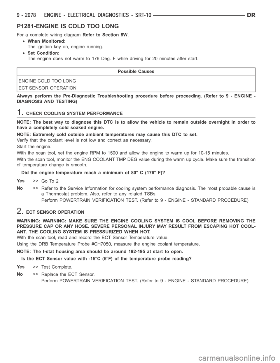
P1281-ENGINE IS COLD TOO LONG
For a complete wiring diagramRefer to Section 8W.
When Monitored:
The ignition key on, engine running.
Set Condition:
The engine does not warm to 176 Deg. F while driving for 20 minutes after start.
Possible Causes
ENGINE COLD TOO LONG
ECT SENSOR OPERATION
Always perform the Pre-Diagnostic Troubleshooting procedure before proceeding. (Refer to 9 - ENGINE -
DIAGNOSIS AND TESTING)
1.CHECK COOLING SYSTEM PERFORMANCE
NOTE: The best way to diagnose this DTC is to allow the vehicle to remain outside overnight in order to
have a completely cold soaked engine.
NOTE: Extremely cold outside ambient temperatures may cause this DTC to set.
Verify that the coolant level is not low and correct as necessary.
Start the engine.
With the scan tool, set the engine RPM to 1500 and allow the engine to warm up for 10-15 minutes.
With the scan tool, monitor the ENG COOLANT TMP DEG value during the warm up cycle. Make sure the transition
of temperature change is smooth.
Did the engine temperature reach a minimum of 80° C (176° F)?
Ye s>>
Go To 2
No>>
Refer to the Service Information for cooling system performance diagnosis. The most probable cause is
a Thermostat problem. Also, refer to any related TSBs.
Perform POWERTRAIN VERIFICATION TEST. (Refer to 9 - ENGINE - STANDARD PROCEDURE)
2.ECT SENSOR OPERATION
WARNING: WARNING: MAKE SURE THE ENGINE COOLING SYSTEM IS COOL BEFORE REMOVING THE
PRESSURE CAP OR ANY HOSE. SEVERE PERSONAL INJURY MAY RESULT FROM ESCAPING HOT COOL-
ANT. THE COOLING SYSTEM IS PRESSURIZED WHEN HOT.
With the scan tool, read and record the ECT Sensor Temperature value.
Using the DRB Temperature Probe #CH7050, measure the engine coolant temperature.
NOTE: The t-stat housing area should be around 192-195 at start to open.
Is the ECT Sensor value with -15°C (5°F) of the temperature probe reading?
Ye s>>
Te s t C o m p l e t e .
No>>
Replace the ECT Sensor.
Perform POWERTRAIN VERIFICATION TEST. (Refer to 9 - ENGINE - STANDARD PROCEDURE)
Page 1388 of 5267
P1282-FUEL PUMP/SYSTEM RELAY CONTROL CIRCUIT
For a complete wiring diagramRefer to Section 8W.
Page 1391 of 5267
P1294-TARGET IDLE NOT REACHED
For a complete wiring diagramRefer to Section 8W.
Page 1394 of 5267
P1296-NO 5-VOLTS TO MAP SENSOR
For a complete wiring diagramRefer to Section 8W.
Page 1398 of 5267
P1297-NO CHANGE IN MAP FROM START TO RUN
For a complete wiring diagramRefer to Section 8W.
Page 1403 of 5267
P1388-AUTO SHUTDOWN RELAY CONTROL CIRCUIT
For a complete wiring diagramRefer to Section 8W.