Page 555 of 5267

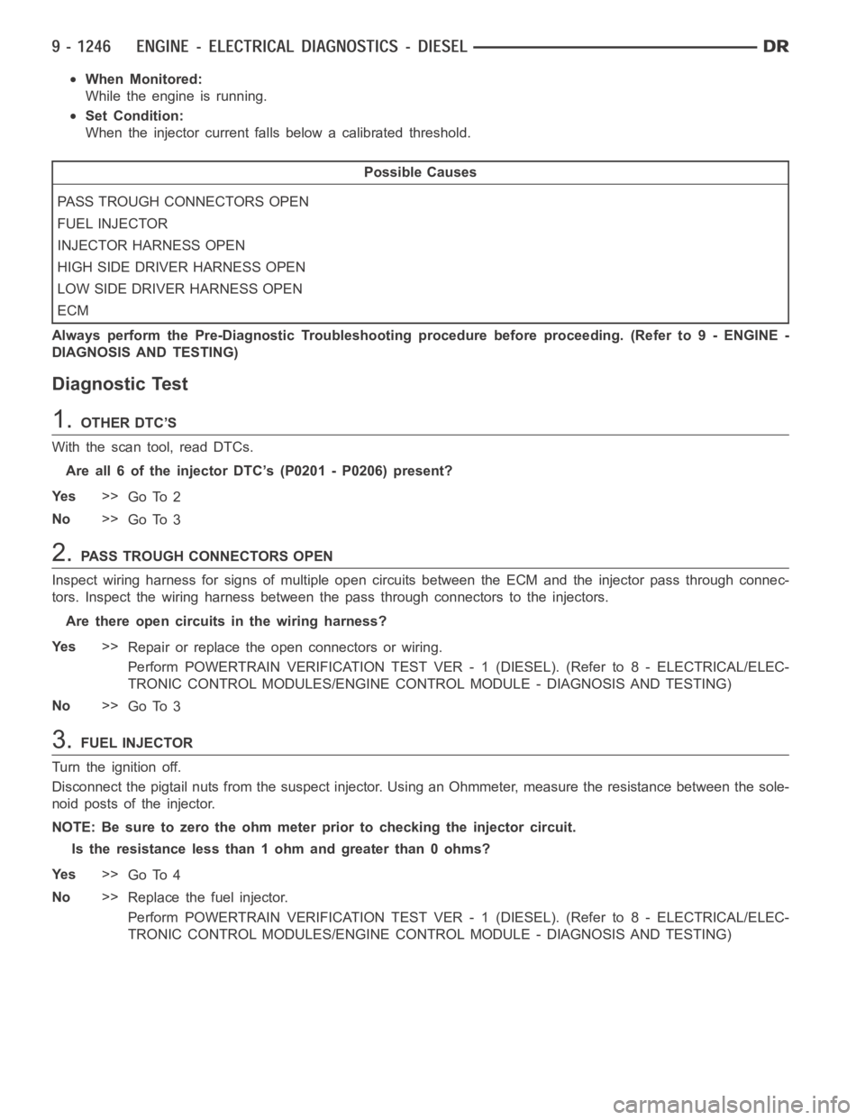
When Monitored:
While the engine is running.
Set Condition:
When the injector current falls below a calibrated threshold.
Possible Causes
PASS TROUGH CONNECTORS OPEN
FUEL INJECTOR
INJECTOR HARNESS OPEN
HIGH SIDE DRIVER HARNESS OPEN
LOW SIDE DRIVER HARNESS OPEN
ECM
Always perform the Pre-Diagnostic Troubleshooting procedure before proceeding. (Refer to 9 - ENGINE -
DIAGNOSIS AND TESTING)
Diagnostic Test
1.OTHER DTC’S
With the scan tool, read DTCs.
Are all 6 of the injector DTC’s (P0201 - P0206) present?
Ye s>>
Go To 2
No>>
Go To 3
2.PASS TROUGH CONNECTORS OPEN
Inspect wiring harness for signs of multiple open circuits between the ECMand the injector pass through connec-
tors. Inspect the wiring harness between the pass through connectors to theinjectors.
Are there open circuits in the wiring harness?
Ye s>>
Repair or replace the open connectors or wiring.
Perform POWERTRAIN VERIFICATION TEST VER - 1 (DIESEL). (Refer to 8 - ELECTRICAL/ELEC-
TRONIC CONTROL MODULES/ENGINE CONTROL MODULE - DIAGNOSIS AND TESTING)
No>>
Go To 3
3.FUEL INJECTOR
Turn the ignition off.
Disconnect the pigtail nuts from the suspect injector. Using an Ohmmeter,measure the resistance between the sole-
noid posts of the injector.
NOTE: Be sure to zero the ohm meter prior to checking the injector circuit.
Is the resistance less than 1 ohm and greater than 0 ohms?
Ye s>>
Go To 4
No>>
Replace the fuel injector.
Perform POWERTRAIN VERIFICATION TEST VER - 1 (DIESEL). (Refer to 8 - ELECTRICAL/ELEC-
TRONIC CONTROL MODULES/ENGINE CONTROL MODULE - DIAGNOSIS AND TESTING)
Page 559 of 5267

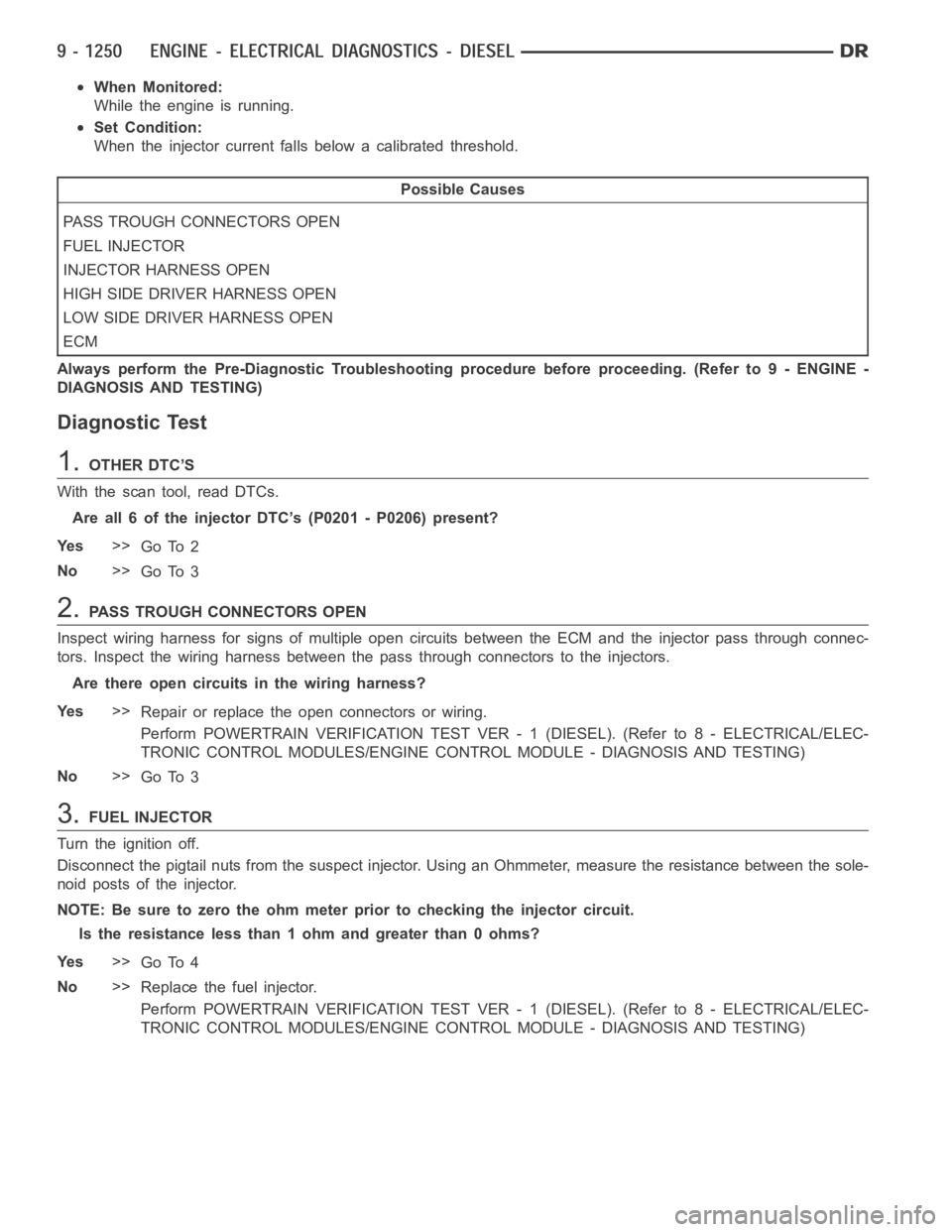
When Monitored:
While the engine is running.
Set Condition:
When the injector current falls below a calibrated threshold.
Possible Causes
PASS TROUGH CONNECTORS OPEN
FUEL INJECTOR
INJECTOR HARNESS OPEN
HIGH SIDE DRIVER HARNESS OPEN
LOW SIDE DRIVER HARNESS OPEN
ECM
Always perform the Pre-Diagnostic Troubleshooting procedure before proceeding. (Refer to 9 - ENGINE -
DIAGNOSIS AND TESTING)
Diagnostic Test
1.OTHER DTC’S
With the scan tool, read DTCs.
Are all 6 of the injector DTC’s (P0201 - P0206) present?
Ye s>>
Go To 2
No>>
Go To 3
2.PASS TROUGH CONNECTORS OPEN
Inspect wiring harness for signs of multiple open circuits between the ECMand the injector pass through connec-
tors. Inspect the wiring harness between the pass through connectors to theinjectors.
Are there open circuits in the wiring harness?
Ye s>>
Repair or replace the open connectors or wiring.
Perform POWERTRAIN VERIFICATION TEST VER - 1 (DIESEL). (Refer to 8 - ELECTRICAL/ELEC-
TRONIC CONTROL MODULES/ENGINE CONTROL MODULE - DIAGNOSIS AND TESTING)
No>>
Go To 3
3.FUEL INJECTOR
Turn the ignition off.
Disconnect the pigtail nuts from the suspect injector. Using an Ohmmeter,measure the resistance between the sole-
noid posts of the injector.
NOTE: Be sure to zero the ohm meter prior to checking the injector circuit.
Is the resistance less than 1 ohm and greater than 0 ohms?
Ye s>>
Go To 4
No>>
Replace the fuel injector.
Perform POWERTRAIN VERIFICATION TEST VER - 1 (DIESEL). (Refer to 8 - ELECTRICAL/ELEC-
TRONIC CONTROL MODULES/ENGINE CONTROL MODULE - DIAGNOSIS AND TESTING)
Page 565 of 5267

When Monitored:
While the engine is running.
Set Condition:
The ECM detects engine speed is above a calibrated threshold.
Possible Causes
OTHER DTC’S
MECHANICAL OVERSPEED OF ENGINE
INTERMITTENT CONDITION
Always perform the Pre-Diagnostic Troubleshooting procedure before proceeding. (Refer to 9 - ENGINE -
DIAGNOSIS AND TESTING)
Diagnostic Test
1.OTHER DTC’S
Turn the ignition on.
With the scan tool, read and record the freeze frame data.
With the scan tool, read the Engine DTC’s.
Is there other Crankshaft position sensor DTC’s set?
Ye s>>
Refer to symptom list for problems related to the other Crankshaft positionsensorDTC’s.
No>>
Go To 2
2.MECHANICAL OVERSPEED OF ENGINE
Visually inspect the engine for signs of mechanical overspeed. Such as, bent push rod, broken rocker arms, bent
valves, etc.
Did you notice any overspeed damage?
Ye s>>
Repair or replace any damaged components.
Perform POWERTRAIN VERIFICATION TEST VER - 1 (DIESEL). (Refer to 8 - ELECTRICAL/ELEC-
TRONIC CONTROL MODULES/ENGINE CONTROL MODULE - DIAGNOSIS AND TESTING)
No>>
Te s t C o m p l e t e .
Page 569 of 5267

When Monitored:
Ignition on.
Set Condition:
The intake air pressure is above a calibrated value past a calibrated amountoftime.
Possible Causes
OTHER CODES
MAP SENSOR
INTERMITTENT CONDITION
Always perform the Pre-Diagnostic Troubleshooting procedure before proceeding. (Refer to 9 - ENGINE -
DIAGNOSIS AND TESTING)
Diagnostic Test
1.OTHER DTC’S
Turn the ignition on.
With the scan tool, read the Engine DTC’s.
Are there any other MAP Sensor related DTC’s.
Ye s>>
Repair other MAP Sensor DTC’s.
Perform POWERTRAIN VERIFICATION TEST VER - 1 (DIESEL). (Refer to 8 - ELECTRICAL/ELEC-
TRONIC CONTROL MODULES/ENGINE CONTROL MODULE - DIAGNOSIS AND TESTING)
No>>
Go To 2
2.MAP SENSOR
Start the engine.
With the scan tool, read the MAP Sensor voltage.
Is the pressure reading of the MAP sensor less than 17.6 psia?
Ye s>>
Go To 3
No>>
Replace the MAP Sensor.
Perform POWERTRAIN VERIFICATION TEST VER - 1 (DIESEL). (Refer to 8 - ELECTRICAL/ELEC-
TRONIC CONTROL MODULES/ENGINE CONTROL MODULE - DIAGNOSIS AND TESTING)
3.MAP SENSOR
Operate the engine under normal driving conditions (no load) for at least 30 seconds.
Monitor the MAP sensor reading with the scan tool.
Did the pressure reading from the MAP sensor go above 29.6 psia for more than2.5 seconds?
Ye s>>
Replace the Map sensor.
Perform POWERTRAIN VERIFICATION TEST VER - 1 (DIESEL). (Refer to 8 - ELECTRICAL/ELEC-
TRONIC CONTROL MODULES/ENGINE CONTROL MODULE - DIAGNOSIS AND TESTING)
No>>
Refer to the INTERMITTENT CONDITION Symptom (Diagnostic Procedure). (Refer to 9 - ENGINE -
DIAGNOSIS AND TESTING)
Page 571 of 5267

When Monitored:
With the ignition on and battery voltage greater than 10.4 volts.
Set Condition:
The circuit voltage to the ECM falls below a calibrated threshold for a certain period of time.
Possible Causes
OTHER DTC’S
(K37) SIGNAL CIRCUIT SHORTED TO (K916) SENSOR RETURN CIRCUIT
(F855) 5-VOLT SUPPLY CIRCUIT SHORTED TO (K916) SENSOR RETURN CIRCUIT
MAP SENSOR
(K37) SIGNAL CIRCUIT OPEN
(F855) 5-VOLT SUPPLY CIRCUIT OPEN
MAP SENSOR (K37) SIGNAL CIRCUIT SHORT TO GROUND
ECM
Always perform the Pre-Diagnostic Troubleshooting procedure before proceeding. (Refer to 9 - ENGINE -
DIAGNOSIS AND TESTING)
Diagnostic Test
1.OTHER DTC’S
Turn the ignition on.
With the scan tool, read the Engine DTC’s.
Is there a 5-volt Supply DTC set?
Ye s>>
Refer to symptom list for problems related to the 5-volt Supply DTC.
Perform POWERTRAIN VERIFICATION TEST VER - 1 (DIESEL). (Refer to 8 - ELECTRICAL/ELEC-
TRONIC CONTROL MODULES/ENGINE CONTROL MODULE - DIAGNOSIS AND TESTING)
No>>
Go To 2
2.HIGH VOLTAGE
Turn the ignition off.
Disconnect the Map sensor harness connector.
Check connectors - Clean/repair as necessary.
Turn the ignition on.
Measure the voltage between the (F855) 5-volt supply circuit and sen-
sor (K916) return circuit of the Map sensor harness connector.
Is the voltage between 4.5 and 5.5 volts?
Ye s>>
Go To 3
No>>
Go To 4
Page 572 of 5267

3.MAP SENSOR
While monitoring the scan tool, jumperthe (F855) 5-volt supply circuit to
the (K37) signal circuit in the Map sensor harness connector.
Did the P0238-MAP SENSOR VOLTAGE TOO HIGH, DTC set?
Ye s>>
Replace the MAP sensor.
Perform POWERTRAIN VERIFICATION TEST VER - 1
(DIESEL). (Refer to 8 - ELECTRICAL/ELECTRONIC CON-
TROL MODULES/ENGINE CONTROL MODULE - DIAG-
NOSIS AND TESTING)
No>>
Go To 4
4.(K37) SIGNAL CIRCUIT SHORTED TO (K916) SENSOR RETURN CIRCUIT
Turn the ignition off.
Disconnect the ECM harness 60 pin connector.
NOTE: Check connectors - Clean/repair as necessary.
Measure the resistance between the (K37) signal circuit and (K916)
sensor return circuit in the MAP sensor harness connector.
Is the resistance greater than 100 K Ohms?
No>>
Repair (K37) signal circuit shorted to (K916) sensor return
circuit or replace harness.
Perform POWERTRAIN VERIFICATION TEST VER - 1
(DIESEL). (Refer to 8 - ELECTRICAL/ELECTRONIC CON-
TROL MODULES/ENGINE CONTROL MODULE - DIAG-
NOSIS AND TESTING)
Ye s>>
Go To 5
5.(F855) 5-VOLT SUPPLY CIRCUIT SHORTED TO (K916) SENSOR RETURN CIRCUIT
Measure the resistance between the (F855) 5-volt supply circuit and
(K916) sensor return circuit in the MAP sensor harness connector.
Is the resistance greater than 100 K Ohms?
No>>
Repair (F855) 5-volt supply circuit shorted to (K916)) sensor
return circuit or replace harness.
Perform POWERTRAIN VERIFICATION TEST VER - 1
(DIESEL). (Refer to 8 - ELECTRICAL/ELECTRONIC CON-
TROL MODULES/ENGINE CONTROL MODULE - DIAG-
NOSIS AND TESTING)
Ye s>>
Go To 6
Page 576 of 5267

When Monitored:
With the ignition on and battery voltage greater than 10.4 volts.
Set Condition:
The circuit voltage to the ECM is above a calibrated threshold for a certainperiod of time.
Possible Causes
OTHER DTC’S
(K37) SIGNAL CIRCUIT SHORTED TO BATTERY
(F855) 5-VOLT SUPPLY CIRCUIT SHORTED TO BATTERY
MAP SENSOR
(K37) SIGNAL CIRCUIT SHORT TO SUPPLY
(F855) 5-VOLT SUPPLY CIRCUIT SHORT TO BATTERY
INTERMITTENT
ECM
Always perform the Pre-Diagnostic Troubleshooting procedure before proceeding. (Refer to 9 - ENGINE -
DIAGNOSIS AND TESTING)
Diagnostic Test
1.OTHER DTC’S
Turn the ignition on.
With the scan tool, read the Engine DTC’s.
Is there a 5-volt Supply DTC set?
Ye s>>
Refer to symptom list for problems related to the 5-volt Supply DTC.
Perform POWERTRAIN VERIFICATION TEST VER - 1 (DIESEL). (Refer to 8 - ELECTRICAL/ELEC-
TRONIC CONTROL MODULES/ENGINE CONTROL MODULE - DIAGNOSIS AND TESTING)
No>>
Go To 2
2.HIGH VOLTAGE
Turn the ignition off.
Disconnect the Map sensor harness connector.
Check connectors - Clean/repair as necessary.
Turn the ignition on.
Measure the voltage between the (F855) 5-volt supply circuit and
(K916) sensor return circuit of the Map sensor harness connector.
Is the voltage between 4.5 and 5.5 volts?
Ye s>>
Go To 3
No>>
Go To 4
Page 578 of 5267
6.(K37) SIGNAL CIRCUIT SHORT TO 5–VOLT SUPPLY
Turn the ignition off.
Disconnect the ECM harness connectors.
Measure the resistance between the (K37) signal circuit of the sensor
harness connector and the (F855) 5-volt supply circuit of the sensor
harness connector.
Is the resistance less than 10 Ohms?
No>>
Go To 7
Ye s>>
Repair or replace the engine harness.
Perform POWERTRAIN VERIFICATION TEST VER - 1
(DIESEL). (Refer to 8 - ELECTRICAL/ELECTRONIC CON-
TROL MODULES/ENGINE CONTROL MODULE - DIAG-
NOSIS AND TESTING)
7.(F855) SENSOR RETURN CIRCUIT OPEN
Measure the resistance between the (K916) sensor return circuit in the
Map sensor harness connector with the (K916) sensor return circuit in
the ECM harness connector.
Is the resistance less than 10 Ohms?
Ye s>>
Go To 8
No>>
Repair or replace the engine harness.
Perform POWERTRAIN VERIFICATION TEST VER - 1
(DIESEL). (Refer to 8 - ELECTRICAL/ELECTRONIC CON-
TROL MODULES/ENGINE CONTROL MODULE - DIAG-
NOSIS AND TESTING)