2006 DODGE RAM SRT-10 transmission oil
[x] Cancel search: transmission oilPage 4018 of 5267
INSTALLATION
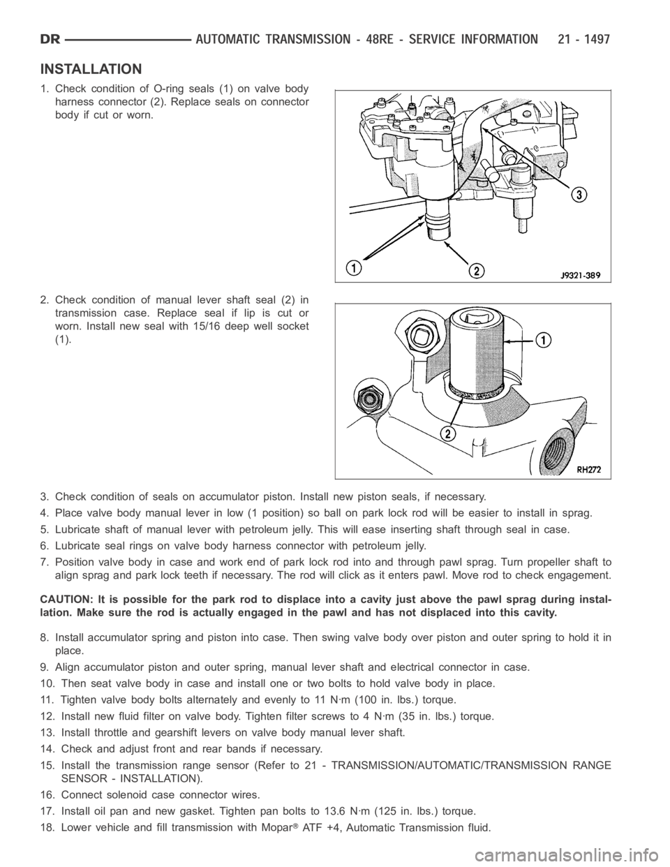
1. Check condition of O-ring seals (1) on valve body
harness connector (2). Replace seals on connector
body if cut or worn.
2. Check condition of manual lever shaft seal (2) in
transmission case. Replace seal if lip is cut or
worn. Install new seal with 15/16 deep well socket
(1).
3. Check condition of seals on accumulator piston. Install new piston seals, if necessary.
4. Place valve body manual lever in low (1 position) so ball on park lock rod will be easier to install in sprag.
5. Lubricate shaft of manual lever with petroleum jelly. This will ease inserting shaft through seal in case.
6. Lubricate seal rings on valve body harness connector with petroleum jelly.
7. Position valve body in case and work end of park lock rod into and through pawl sprag. Turn propeller shaft to
align sprag and park lock teeth if necessary. The rod will click as it enterspawl. Move rod to check engagement.
CAUTION: It is possible for the park rod to displace into a cavity just abovethe pawl sprag during instal-
lation. Make sure the rod is actually engaged in the pawl and has not displaced into this cavity.
8. Install accumulator spring and piston into case. Then swing valve body overpistonandouterspringtoholditin
place.
9. Align accumulator piston and outer spring, manual lever shaft and electrical connector in case.
10. Then seat valve body in case and install one or two bolts to hold valve bodyinplace.
11. Tighten valve body bolts alternately and evenly to 11 Nꞏm (100 in. lbs.)torque.
12. Install new fluid filter on valve body. Tighten filter screws to 4 Nꞏm (35 in. lbs.) torque.
13. Install throttle and gearshift levers on valve body manual lever shaft.
14. Check and adjust front and rear bands if necessary.
15. Install the transmission range sensor (Refer to 21 - TRANSMISSION/AUTOMATIC/TRANSMISSION RANGE
SENSOR - INSTALLATION).
16. Connect solenoid case connector wires.
17. Install oil pan and new gasket. Tighten pan bolts to 13.6 Nꞏm (125 in. lbs.) torque.
18. Lower vehicle and fill transmission with Mopar
ATF +4, Automatic Transmission fluid.
Page 4087 of 5267
Condition Possible Cause Correction
Lubricant leaking from output shaft
seal or vent.1) Transfer case overfilled. 1) Drain lubricant to the correct
level.
2) Vent closed or restricted. 2) Clear or replace vent as
necessary.
3) Output shaft seals damaged or
installed incorrectly.3) Replace seal as necessary.
Check to ensure that another
component, the propeller shaft slip
yoke for example, is not causing
damage to seal.
Abnormal tire wear. 1) Extended operation on hard, dry
surfaces in the 4H position.1) Operate vehicle in the 2H
position on hard, dry surfaces.
REMOVAL
1. Raise and support vehicle.
2. Remove skid plate, if equipped. (Refer to 13 - FRAMES & BUMPERS/FRAME/TRANSFER CASE SKID PLATE
- REMOVAL)
3. Position drain oil container under transfer case.
4. Remove transfer case drain plug and drain lubricant into container.
5. Disconnect vent hose and transfer case position sensor connector.
6. Disconnect shift rod from grommet in transfer case shift lever, or from floor shift arm whichever provides easy
access. Use channel lock style pliers to press rod out of lever grommet.
7. Support transmission with jack stand.
8. Mark front and rear propeller shafts for assembly reference.
9. Remove front and rear propeller shafts. (Refer to 3 - DIFFERENTIAL & DRIVELINE/PROPELLER SHAFT/PRO-
PELLER SHAFT - REMOVAL)
10. Support transfer case with suitable jack. Secure transfer case to jackwith safety chains.
11. Remove nuts attaching transfer case to transmission.
12. Move transfer case assembly rearward until free of transmission outputshaft.
13. Lower jack and move transfer case from under vehicle.
DISASSEMBLY
Position transfer case in a shallow drain pan. Remove drain plug and drain any remaining lubricant remaining in
case.
SHIFT LEVER AND FRONT OUTPUT SHAFT SEAL
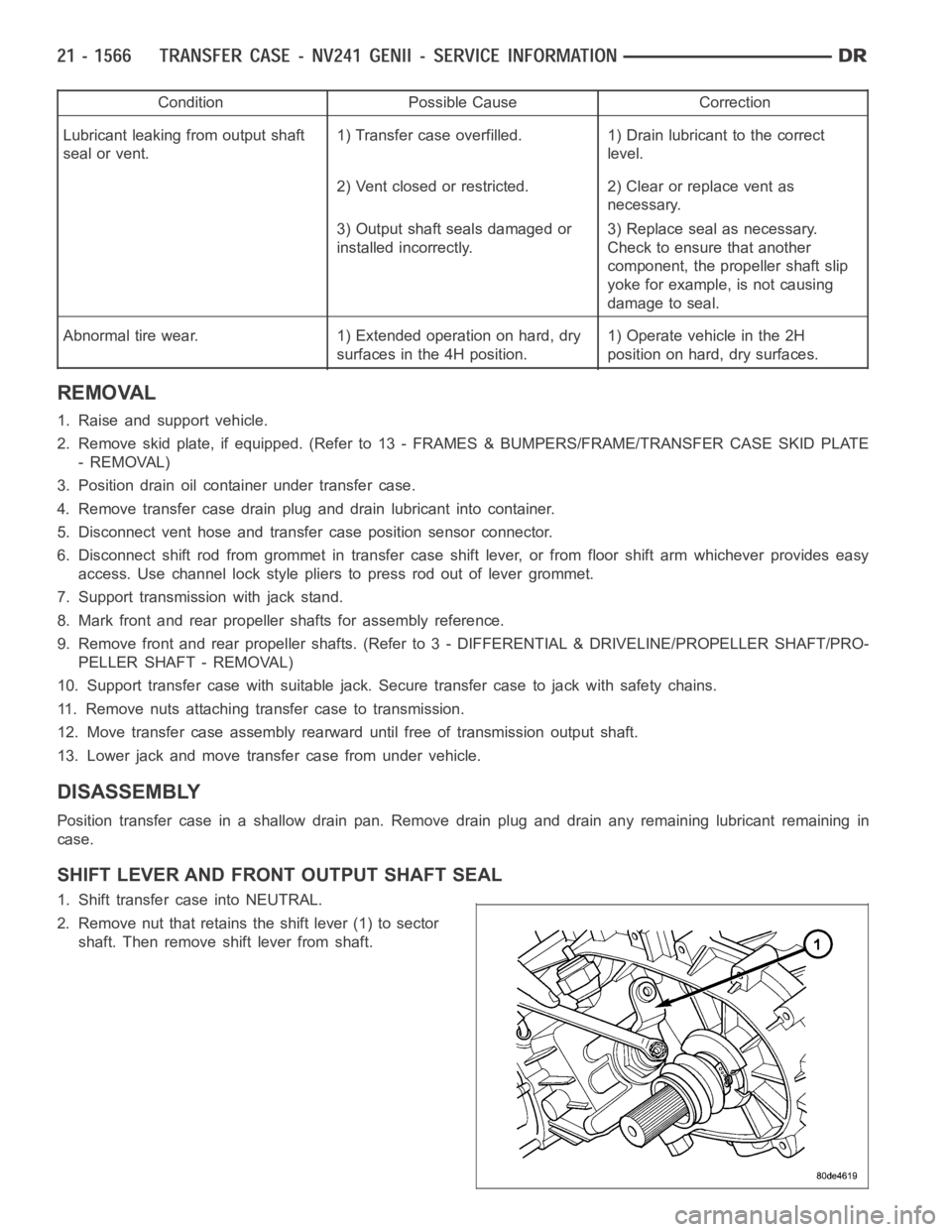
1. Shift transfer case into NEUTRAL.
2. Remove nut that retains the shift lever (1) to sector
shaft. Then remove shift lever from shaft.
Page 4115 of 5267
SEAL BOOT
1. Install the front output shaft seal slinger with Oil Slinger Installer 8840. Install the slinger onto the shaft until the
tool contacts the rear of the output shaft.
2. Install a new seal boot clamp onto the seal boot.
3. Install the seal boot and clamp onto the slinger hub and tighten the clampwith Crimp Tool C-4975-A.
REAR EXTENSION
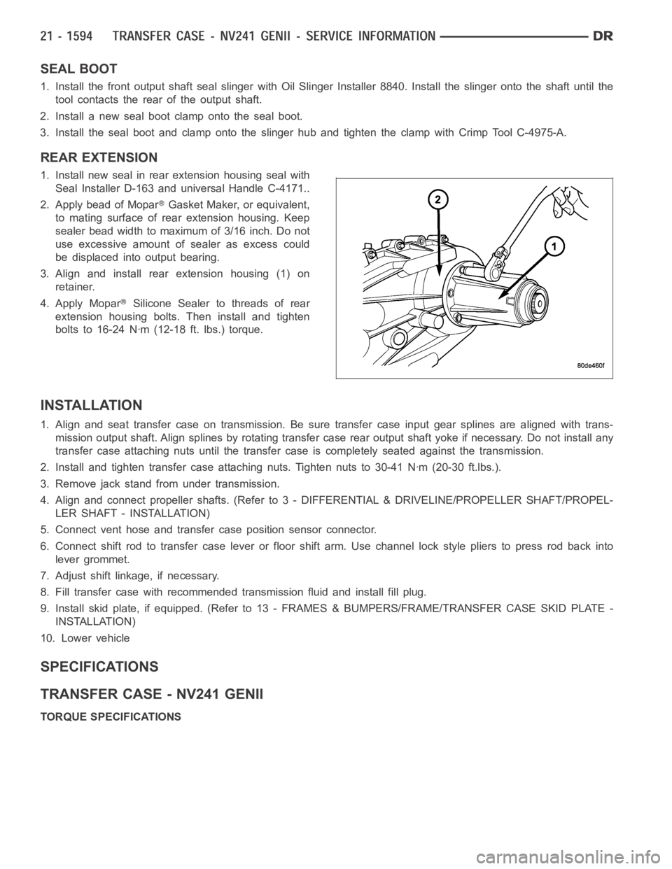
1. Install new seal in rear extension housing seal with
Seal Installer D-163 and universal Handle C-4171..
2. Apply bead of Mopar
Gasket Maker, or equivalent,
to mating surface of rear extension housing. Keep
sealer bead width to maximum of 3/16 inch. Do not
use excessive amount of sealer as excess could
be displaced into output bearing.
3. Align and install rear extension housing (1) on
retainer.
4. Apply Mopar
Silicone Sealer to threads of rear
extension housing bolts. Then install and tighten
bolts to 16-24 Nꞏm (12-18 ft. lbs.) torque.
INSTALLATION
1. Align and seat transfer case on transmission. Be sure transfer case input gear splines are aligned with trans-
mission output shaft. Align splines by rotating transfer case rear outputshaft yoke if necessary. Do not install any
transfer case attaching nuts until the transfer case is completely seatedagainst the transmission.
2. Install and tighten transfer case attaching nuts. Tighten nuts to 30-41Nꞏm (20-30 ft.lbs.).
3. Remove jack stand from under transmission.
4. Align and connect propeller shafts. (Refer to 3 - DIFFERENTIAL & DRIVELINE/PROPELLER SHAFT/PROPEL-
LER SHAFT - INSTALLATION)
5. Connect vent hose and transfer case position sensor connector.
6. Connect shift rod to transfer case lever or floor shift arm. Use channel lock style pliers to press rod back into
lever grommet.
7. Adjust shift linkage, if necessary.
8. Fill transfer case with recommended transmission fluid and install fillplug.
9. Install skid plate, if equipped. (Refer to 13 - FRAMES & BUMPERS/FRAME/TRANSFER CASE SKID PLATE -
INSTALLATION)
10. Lower vehicle
SPECIFICATIONS
TRANSFER CASE - NV241 GENII
TORQUE SPECIFICATIONS
Page 4129 of 5267
Condition Possible Cause Correction
Lubricant leaking from output shaft
seal or vent.1) Transfer case overfilled. 1) Drain lubricant to the correct
level.
2) Vent closed or restricted. 2) Clear or replace vent as
necessary.
3) Output shaft seals damaged or
installed incorrectly.3) Replace seal as necessary.
Check to ensure that another
component, the propeller shaft slip
yoke for example, is not causing
damage to seal.
Abnormal tire wear. 1) Extended operation on hard, dry
surfaces in the 4H position.1) Operate vehicle in the 2H
position on hard, dry surfaces.
REMOVAL
1. Raise and support vehicle.
2. Remove skid plate, if equipped. (Refer to 13 - FRAMES & BUMPERS/FRAME/TRANSFER CASE SKID PLATE
- REMOVAL)
3. Position drain oil container under transfer case.
4. Remove transfer case drain plug and drain lubricant into container.
5. Disconnect vent hose and transfer case position sensor connector.
6. Disconnect shift rod from grommet in transfer case shift lever, or from floor shift arm whichever provides easy
access. Use channel lock style pliers to press rod out of lever grommet.
7. Support transmission with jack stand.
8. Mark front and rear propeller shafts for assembly reference.
9. Remove front and rear propeller shafts. (Refer to 3 - DIFFERENTIAL & DRIVELINE/PROPELLER SHAFT/PRO-
PELLER SHAFT - REMOVAL)
10. Support transfer case with suitable jack. Secure transfer case to jackwith safety chains.
11. Remove nuts attaching transfer case to transmission.
12. Move transfer case assembly rearward until free of transmission outputshaft.
13. Lower jack and move transfer case from under vehicle.
DISASSEMBLY
Position transfer case in a shallow drain pan. Remove drain plug and drain any remaining lubricant remaining in
case.
Page 4205 of 5267
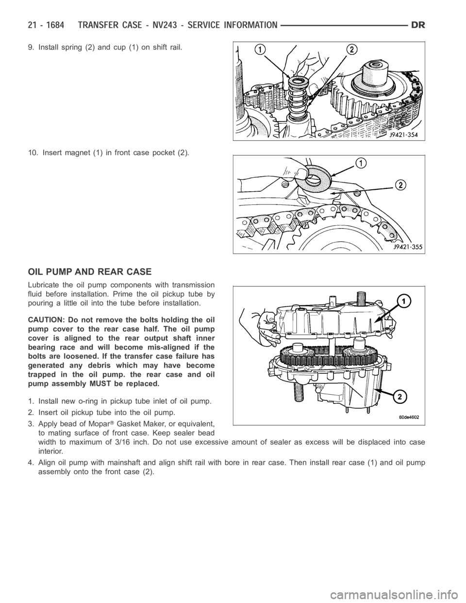
9. Install spring (2) and cup (1) on shift rail.
10. Insert magnet (1) in front case pocket (2).
OIL PUMP AND REAR CASE
Lubricate the oil pump components with transmission
fluid before installation. Prime the oil pickup tube by
pouring a little oil into the tube before installation.
CAUTION: Do not remove the bolts holding the oil
pump cover to the rear case half. The oil pump
cover is aligned to the rear output shaft inner
bearing race and will become mis-aligned if the
bolts are loosened. If the transfer case failure has
generated any debris which may have become
trapped in the oil pump. the rear case and oil
pump assembly MUST be replaced.
1. Install new o-ring in pickup tube inlet of oil pump.
2. Insert oil pickup tube into the oil pump.
3. Apply bead of Mopar
Gasket Maker, or equivalent,
to mating surface of front case. Keep sealer bead
width to maximum of 3/16 inch. Do not use excessive amount of sealer as excess will be displaced into case
interior.
4. Align oil pump with mainshaft and align shift rail with bore in rear case.Then install rear case (1) and oil pump
assembly onto the front case (2).
Page 4207 of 5267
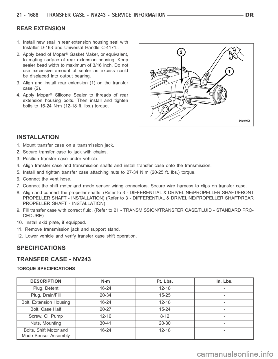
REAR EXTENSION
1. Install new seal in rear extension housing seal with
Installer D-163 and Universal Handle C-4171..
2. Apply bead of Mopar
Gasket Maker, or equivalent,
to mating surface of rear extension housing. Keep
sealer bead width to maximum of 3/16 inch. Do not
use excessive amount of sealer as excess could
be displaced into output bearing.
3. Align and install rear extension (1) on the transfer
case (2).
4. Apply Mopar
Silicone Sealer to threads of rear
extension housing bolts. Then install and tighten
bolts to 16-24 Nꞏm (12-18 ft. lbs.) torque.
INSTALLATION
1. Mount transfer case on a transmission jack.
2. Secure transfer case to jack with chains.
3. Position transfer case under vehicle.
4. Align transfer case and transmission shafts and install transfer case onto the transmission.
5. Install and tighten transfer case attaching nuts to 27-34 Nꞏm (20-25 ft.lbs.) torque.
6. Connect the vent hose.
7. Connect the shift motor and mode sensor wiring connectors. Secure wire harness to clips on transfer case.
8. Align and connect the propeller shafts. (Refer to 3 - DIFFERENTIAL & DRIVELINE/PROPELLER SHAFT/FRONT
PROPELLER SHAFT - INSTALLATION) (Refer to 3 - DIFFERENTIAL & DRIVELINE/PROPELLER SHAFT/REAR
PROPELLER SHAFT - INSTALLATION)
9. Fill transfer case with correct fluid. (Refer to 21 - TRANSMISSION/TRANSFER CASE/FLUID - STANDARD PRO-
CEDURE)
10. Install skid plate, if equipped.
11. Remove transmission jack and support stand.
12. Lower vehicle and verify transfer case shift operation.
SPECIFICATIONS
TRANSFER CASE - NV243
TORQUE SPECIFICATIONS
DESCRIPTION N-m Ft. Lbs. In. Lbs.
Plug, Detent 16-24 12-18 -
Plug, Drain/Fill 20-34 15-25 -
Bolt, Extension Housing 16-24 12-18 -
Bolt, Case Half 20-27 15-24 -
Screw, Oil Pump 12-16 8-12 -
Nuts, Mounting 30-41 20-30 -
Bolts, Shift Motor and
Mode Sensor Assembly16-24 12-18 -
Page 4249 of 5267
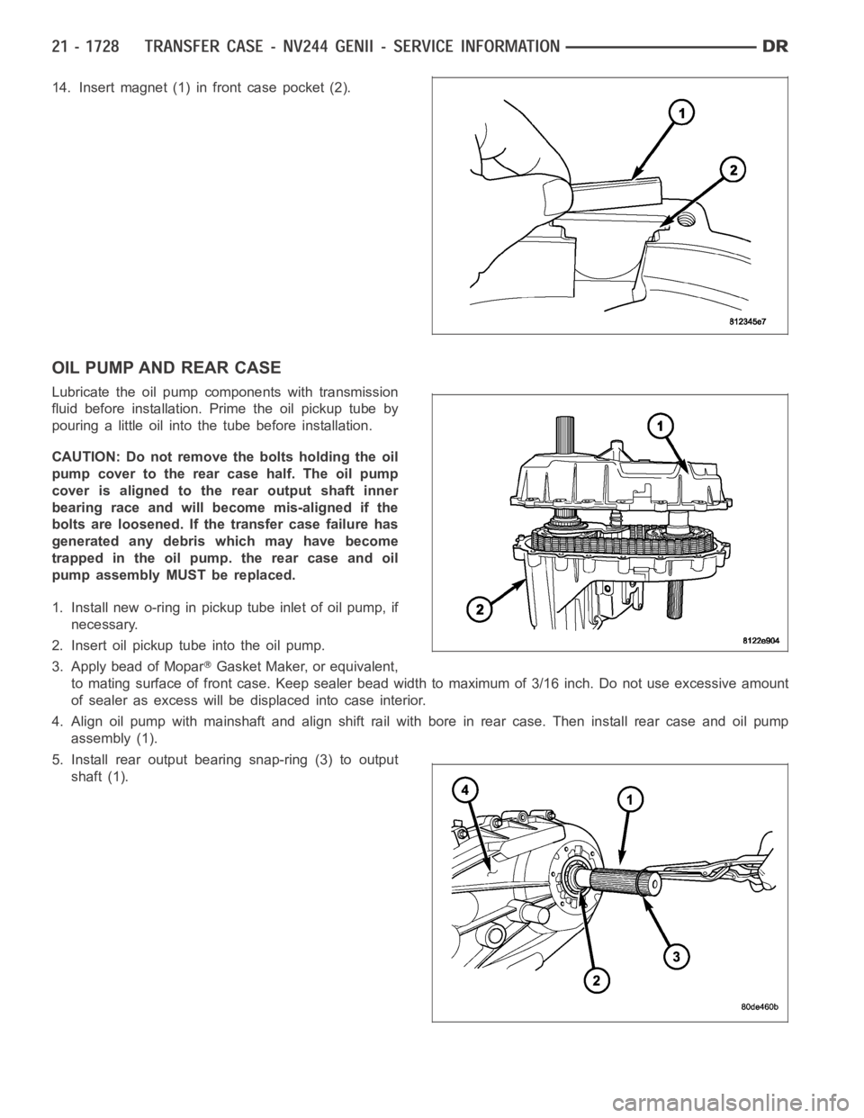
14. Insert magnet (1) in front case pocket (2).
OIL PUMP AND REAR CASE
Lubricate the oil pump components with transmission
fluid before installation. Prime the oil pickup tube by
pouring a little oil into the tube before installation.
CAUTION: Do not remove the bolts holding the oil
pump cover to the rear case half. The oil pump
cover is aligned to the rear output shaft inner
bearing race and will become mis-aligned if the
bolts are loosened. If the transfer case failure has
generated any debris which may have become
trapped in the oil pump. the rear case and oil
pump assembly MUST be replaced.
1. Install new o-ring in pickup tube inlet of oil pump, if
necessary.
2. Insert oil pickup tube into the oil pump.
3. Apply bead of Mopar
Gasket Maker, or equivalent,
to mating surface of front case. Keep sealer bead width to maximum of 3/16 inch. Do not use excessive amount
of sealer as excess will be displaced into case interior.
4. Align oil pump with mainshaft and align shift rail with bore in rear case.Then install rear case and oil pump
assembly (1).
5. Install rear output bearing snap-ring (3) to output
shaft (1).
Page 4251 of 5267

REAR EXTENSION
1. Install new seal in rear extension housing seal with
Seal Installer D-163 and Universal Handle C-4171.
Verify that the weep hole in the rubber is oriented
downward.
2. Apply bead of Mopar
Gasket Maker, or equivalent,
to mating surface of rear extension housing. Keep
sealer bead width to maximum of 3/16 inch. Do not
use excessive amount of sealer as excess could
be displaced into output bearing.
3. Align and install rear extension (1) on the transfer
case (2).
4. Apply Mopar
Silicone Sealer to threads of rear
extension housing bolts. Then install and tighten
bolts to 16-24 Nꞏm (12-18 ft. lbs.) torque.
INSTALLATION
1. Mount transfer case on a transmission jack.
2. Secure transfer case to jack with chains.
3. Position transfer case under vehicle.
4. Align transfer case and transmission shafts and install transfer case onto the transmission.
5. Install and tighten transfer case attaching nuts to 27-34 Nꞏm (20-25 ft.lbs.) torque.
6. Connect the vent hose.
7. Connect the shift motor and mode sensor wiring connectors. Secure wire harness to clips on transfer case.
8. Align and connect the propeller shafts. (Refer to 3 - DIFFERENTIAL & DRIVELINE/PROPELLER SHAFT/FRONT
PROPELLER SHAFT - INSTALLATION) (Refer to 3 - DIFFERENTIAL & DRIVELINE/PROPELLER SHAFT/REAR
PROPELLER SHAFT - INSTALLATION)
9. Fill transfer case with correct fluid. (Refer to 21 - TRANSMISSION/TRANSFER CASE/FLUID - STANDARD PRO-
CEDURE)
10. Install skid plate, if equipped.
11. Remove transmission jack and support stand.
12. Lower vehicle and verify transfer case shift operation.
SPECIFICATIONS
TRANSFER CASE - NV244 GENII
TORQUE SPECIFICATIONS
DESCRIPTION N-m Ft. Lbs. In. Lbs.
Plug, Detent 16-24 12-18 -
Plug, Drain/Fill 20-34 15-25 -
Bolt, Extension Housing 16-24 12-18 -
Bolt, Case Half 25-28 18-21 -
Screw, Oil Pump 14-19 10-14 -
Nuts, Mounting 30-41 20-30 -
Bolts, Shift Motor and
Mode Sensor Assembly16-24 12-18 -