2006 DODGE RAM SRT-10 transmission oil
[x] Cancel search: transmission oilPage 3819 of 5267
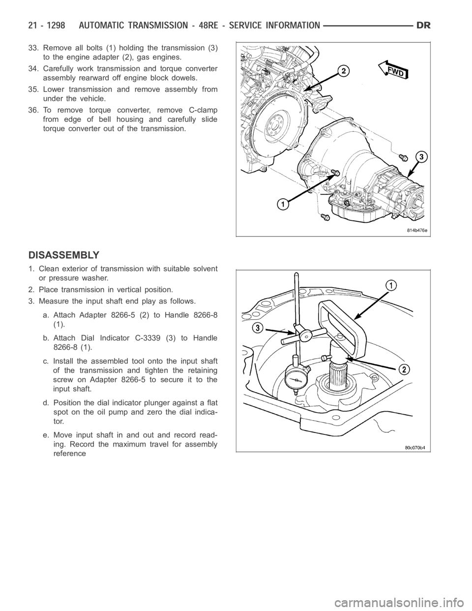
33. Remove all bolts (1) holding the transmission (3)
to the engine adapter (2), gas engines.
34. Carefully work transmission and torque converter
assembly rearward off engine block dowels.
35. Lower transmission and remove assembly from
under the vehicle.
36. To remove torque converter, remove C-clamp
from edge of bell housing and carefully slide
torque converter out of the transmission.
DISASSEMBLY
1. Clean exterior of transmission with suitable solvent
or pressure washer.
2. Place transmission in vertical position.
3. Measure the input shaft end play as follows.
a. Attach Adapter 8266-5 (2) to Handle 8266-8
(1).
b. Attach Dial Indicator C-3339 (3) to Handle
8266-8 (1).
c. Install the assembled tool onto the input shaft
of the transmission and tighten the retaining
screw on Adapter 8266-5 to secure it to the
input shaft.
d. Position the dial indicator plunger against a flat
spot on the oil pump and zero the dial indica-
tor.
e. Move input shaft in and out and record read-
ing. Record the maximum travel for assembly
reference
Page 3820 of 5267
4. Removetheoverdriveunitfromthemaintransmis-
sion case. If overdrive unit is not to be serviced,
install Alignment Shaft 6227-2 into the overdrive
unit to prevent misalignment of the overdrive
clutches during service ofmain transmission com-
ponents.
5. Remove throttle and shift levers from valve body
manual shaft and throttle lever shaft.
6. Remove transmission oil pan and gasket.
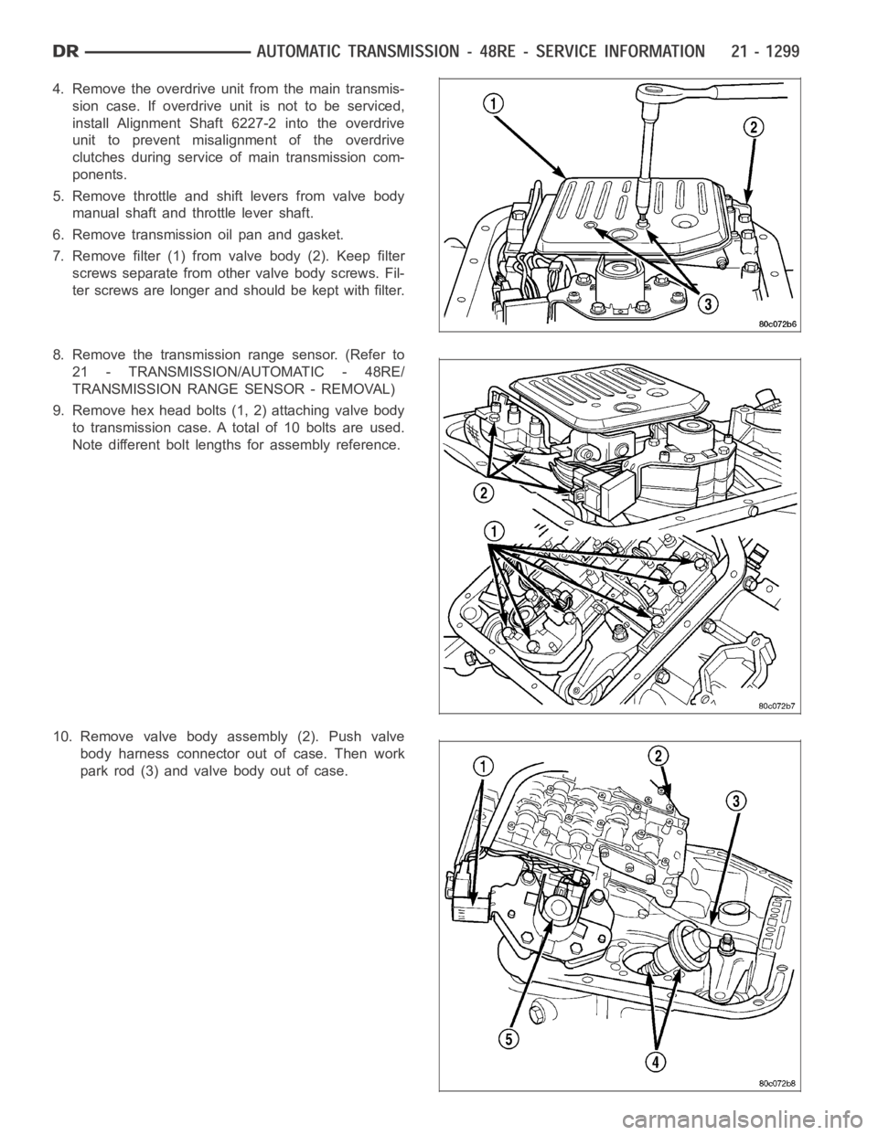
7. Remove filter (1) from valve body (2). Keep filter
screws separate from other valve body screws. Fil-
ter screws are longer and should be kept with filter.
8. Remove the transmission range sensor. (Refer to
21 - TRANSMISSION/AUTOMATIC - 48RE/
TRANSMISSION RANGE SENSOR - REMOVAL)
9. Remove hex head bolts (1, 2) attaching valve body
to transmission case. A total of 10 bolts are used.
Note different bolt lengths for assembly reference.
10. Remove valve body assembly (2). Push valve
body harness connector out of case. Then work
park rod (3) and valve body out of case.
Page 3827 of 5267
32. Remove rear band adjusting lever and reaction
pin.
33. Remove rear band.
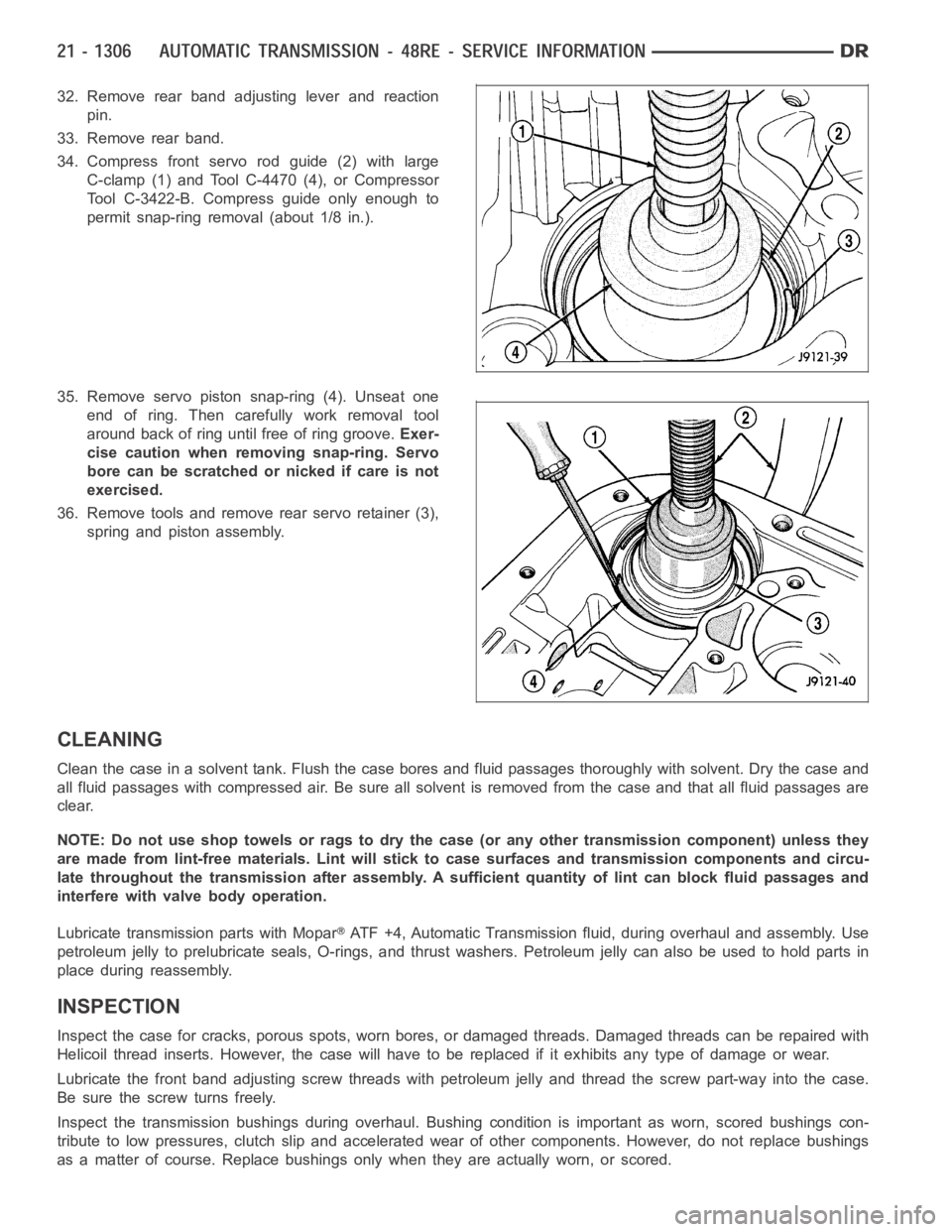
34. Compress front servo rod guide (2) with large
C-clamp (1) and Tool C-4470 (4), or Compressor
Tool C-3422-B. Compress guide only enough to
permit snap-ring removal (about 1/8 in.).
35. Remove servo piston snap-ring (4). Unseat one
end of ring. Then carefully work removal tool
around back of ring until free of ring groove.Exer-
cise caution when removing snap-ring. Servo
bore can be scratched or nicked if care is not
exercised.
36. Remove tools and remove rear servo retainer (3),
spring and piston assembly.
CLEANING
Clean the case in a solvent tank. Flush the case bores and fluid passages thoroughly with solvent. Dry the case and
all fluid passages with compressed air. Be sure all solvent is removed fromthe case and that all fluid passages are
clear.
NOTE: Do not use shop towels or rags to dry the case (or any other transmission component) unless they
aremadefromlint-freematerials.Lintwillsticktocasesurfacesandtransmission components and circu-
late throughout the transmission after assembly. A sufficient quantity of lint can block fluid passages and
interfere with valve body operation.
Lubricate transmission parts with Mopar
ATF +4, Automatic Transmission fluid, during overhaul and assembly. Use
petroleum jelly to prelubricate seals, O-rings, and thrust washers. Petroleumjellycanalsobeusedtoholdpartsin
place during reassembly.
INSPECTION
Inspect the case for cracks, porous spots, worn bores, or damaged threads.Damaged threads can be repaired with
Helicoil thread inserts. However, the case will have to be replaced if it exhibits any type of damage or wear.
Lubricate the front band adjusting screw threads with petroleum jelly andthread the screw part-way into the case.
Be sure the screw turns freely.
Inspect the transmission bushings during overhaul. Bushing condition isimportant as worn, scored bushings con-
tribute to low pressures, clutch slipand accelerated wear of other components. However, do not replace bushings
as a matter of course. Replace bushings only when they are actually worn, orscored.
Page 3828 of 5267
The use of crocus cloth is permissible where necessary, providing it is usedcarefully.Whenusedonshafts,or
valves, use extreme care to avoid rounding off sharp edges. Sharp edges arevital as they prevent foreign matter
from getting between the valve and valve bore.
Do not reuse oil seals, gaskets, seal rings, or O-rings during overhaul. Replace these parts as a matter of course.
Also do not reuse snap rings or E-clips that are bent or distorted. Replace these parts as well.
ASSEMBLY
Do not allow dirt, grease, or foreign material to enter the case or transmission components during assembly. Keep
the transmission case and components clean. Also make sure the tools and workbench area used for reassembly
operations are equally clean.
Shop towels used for wiping off tools and your hands must be made fromlint freematerials. Lint will stick to trans-
mission parts and could interfere with valve operation or even restrict fluid passages.
Lubricate transmission clutch and gear components with Mopar
ATF +4 during reassembly. Soak clutch discs in
transmission fluid before installation.
Use petroleum jelly on piston seals and o-rings to ease installation. Petroleumjellycanalsobeusedtolubricate
and hold thrust washers and plates in position during assembly.
Do not use chassis grease, bearing grease, white grease, or similar lubricants on any part.These types of
lubricants can eventually block or restrict fluid passages and valve operation. Use petroleum jelly only.
Do not force parts into place. The transmission components and sub-assemblies are easily installed by hand when
properly aligned. If a part seems difficult to install, it is either misaligned or incorrectly assembled. Verify that thrust
washers, thrust plates and seal rings are correctly positioned.
The planetary geartrain, front/rear clutch assemblies and oil pump are all much easier to install when the transmis-
sion case is upright. Either tilt the case upward with wood blocks, or cut a hole in the bench large enough for the
intermediate shaft and rear support. Then lower the shaft and support intothe hole and support the rear of the case
directly on the bench.
FRONT/REAR SERVO
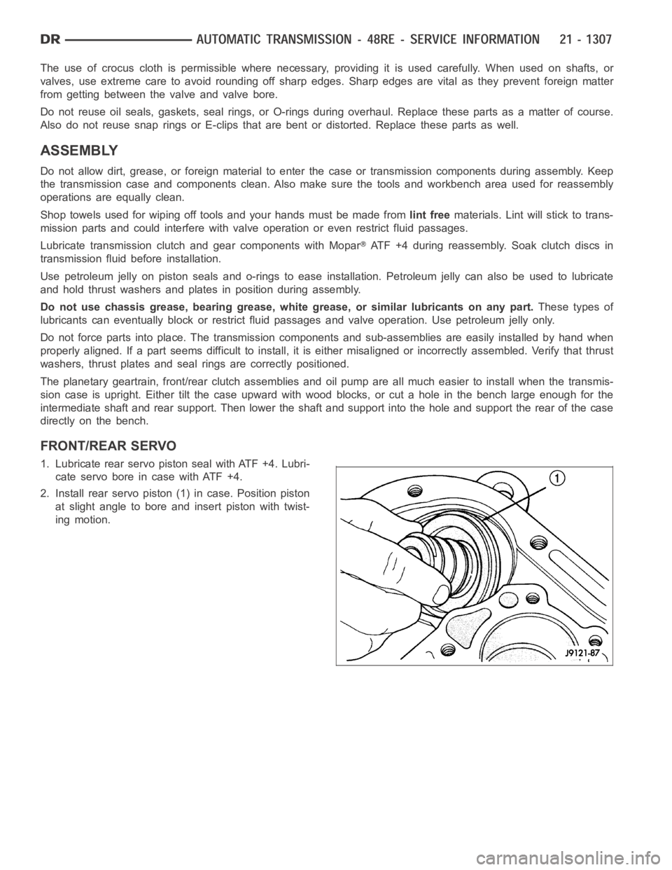
1. Lubricate rear servo piston seal with ATF +4. Lubri-
cateservoboreincasewithATF+4.
2. Install rear servo piston (1) in case. Position piston
at slight angle to bore and insert piston with twist-
ing motion.
Page 3833 of 5267
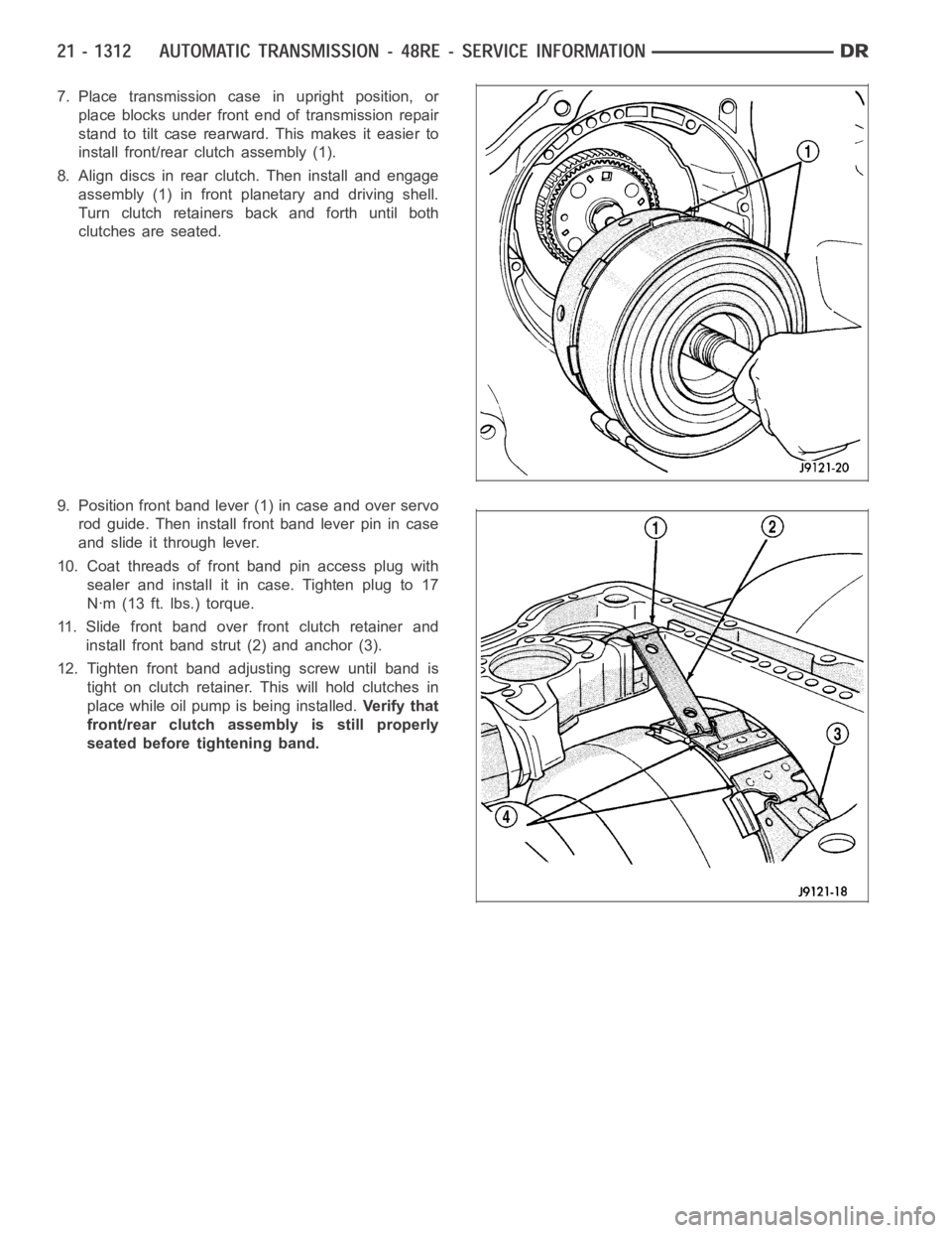
7. Place transmission case in upright position, or
place blocks under front end of transmission repair
stand to tilt case rearward. This makes it easier to
install front/rear clutch assembly (1).
8. Align discs in rear clutch. Then install and engage
assembly (1) in front planetary and driving shell.
Turn clutch retainers back and forth until both
clutches are seated.
9. Position front band lever (1) in case and over servo
rod guide. Then install front band lever pin in case
and slide it through lever.
10. Coat threads of front band pin access plug with
sealer and install it in case. Tighten plug to 17
Nꞏm (13 ft. lbs.) torque.
11. Slide front band over front clutch retainer and
install front band strut (2) and anchor (3).
12. Tighten front band adjusting screw until band is
tight on clutch retainer. This will hold clutches in
place while oil pump is being installed.Ve r i f y t h a t
front/rear clutch assembly is still properly
seated before tightening band.
Page 3835 of 5267
5. Check the torque converter hub seal ring on the
reaction shaft for damage. Also check that the seal
ring rotates freely in the reaction shaft groove.
Replace the seal if necessary.
6. Lubricate oil pump seals with petroleum Mopar
AT F + 4 .
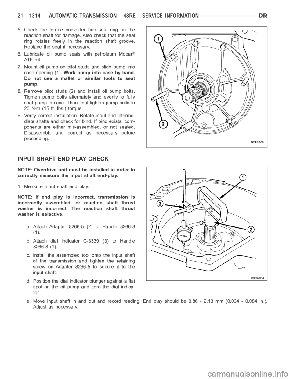
7. Mount oil pump on pilot studs and slide pump into
case opening (1).Work pump into case by hand.
Do not use a mallet or similar tools to seat
pump.
8. Remove pilot studs (2) and install oil pump bolts.
Tighten pump bolts alternately and evenly to fully
seat pump in case. Then final-tighten pump bolts to
20 Nꞏm (15 ft. lbs.) torque.
9. Verify correct installation. Rotate input and interme-
diate shafts and check for bind. If bind exists, com-
ponents are either mis-assembled, or not seated.
Disassemble and correct as necessary before
proceeding.
INPUT SHAFT END PLAY CHECK
NOTE: Overdrive unit must be installed in order to
correctly measure the input shaft end-play.
1. Measure input shaft end play.
NOTE: If end play is incorrect, transmission is
incorrectly assembled, or reaction shaft thrust
washer is incorrect. The reaction shaft thrust
washer is selective.
a. Attach Adapter 8266-5 (2) to Handle 8266-8
(1).
b. Attach dial indicator C-3339 (3) to Handle
8266-8 (1).
c. Install the assembled tool onto the input shaft
of the transmission and tighten the retaining
screw on Adapter 8266-5 to secure it to the
input shaft.
d. Position the dial indicator plunger against a flat
spot on the oil pump and zero the dial indica-
tor.
e. Move input shaft in and out and record reading. End play should be 0.86 - 2.13 mm (0.034 - 0.084 in.).
Adjust as necessary.
Page 3836 of 5267
ACCUMULATOR, VALVE BODY, OIL PAN, AND TORQUE CONVERTER
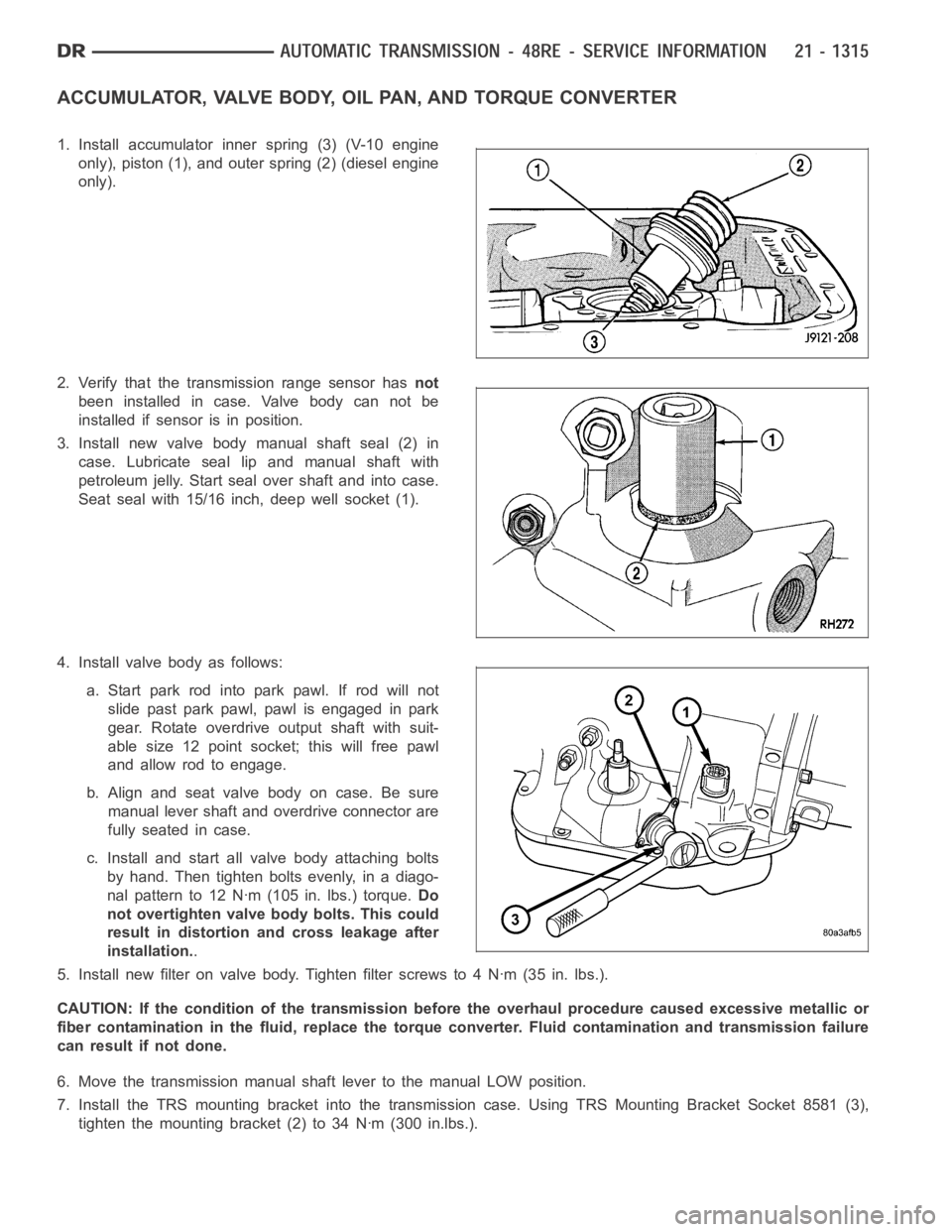
1. Install accumulator inner spring (3) (V-10 engine
only), piston (1), and outer spring (2) (diesel engine
only).
2. Verify that the transmission range sensor hasnot
been installed in case. Valve body can not be
installed if sensor is in position.
3. Install new valve body manual shaft seal (2) in
case. Lubricate seal lip and manual shaft with
petroleum jelly. Start seal over shaft and into case.
Seat seal with 15/16 inch, deep well socket (1).
4. Install valve body as follows:
a. Start park rod into park pawl. If rod will not
slide past park pawl, pawl is engaged in park
gear. Rotate overdrive output shaft with suit-
able size 12 point socket; this will free pawl
and allow rod to engage.
b.Alignandseatvalvebodyoncase.Besure
manual lever shaft and overdrive connector are
fully seated in case.
c. Install and start all valve body attaching bolts
by hand. Then tighten bolts evenly, in a diago-
nal pattern to 12 Nꞏm (105 in. lbs.) torque.Do
not overtighten valve body bolts. This could
result in distortion and cross leakage after
installation..
5. Install new filter on valve body. Tighten filter screws to 4 Nꞏm (35 in. lbs.).
CAUTION: If the condition of the transmission before the overhaul procedure caused excessive metallic or
fiber contamination in the fluid, replace the torque converter. Fluid contamination and transmission failure
can result if not done.
6. Move the transmission manual shaft lever to the manual LOW position.
7. Install the TRS mounting bracket into the transmission case. Using TRS Mounting Bracket Socket 8581 (3),
tighten the mounting bracket (2) to 34 Nꞏm (300 in.lbs.).
Page 3837 of 5267
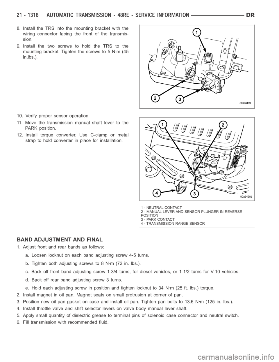
8. Install the TRS into the mounting bracket with the
wiring connector facing the front of the transmis-
sion.
9. Install the two screws to hold the TRS to the
mounting bracket. Tighten the screws to 5 Nꞏm (45
in.lbs.).
10. Verify proper sensor operation.
11. Move the transmission manual shaft lever to the
PARK position.
12. Install torque converter. Use C-clamp or metal
strap to hold converter in place for installation.
BAND ADJUSTMENT AND FINAL
1. Adjust front and rear bands as follows:
a. Loosen locknut on each band adjusting screw 4-5 turns.
b. Tighten both adjusting screws to 8 Nꞏm (72 in. lbs.).
c. Back off front band adjusting screw 1-3/4 turns, for diesel vehicles, or1-1/2 turns for V-10 vehicles.
d. Back off rear band adjusting screw 3 turns.
e. Hold each adjusting screw in position and tighten locknut to 34 Nꞏm (25 ft. lbs.) torque.
2. Install magnet in oil pan. Magnet seats on small protrusion at corner of pan.
3. Position new oil pan gasket on case and install oil pan. Tighten pan boltsto 13.6 Nꞏm (125 in. lbs.).
4. Install throttle valve and shift selector levers on valve body manual lever shaft.
5. Apply small quantity of dielectric grease to terminal pins of solenoid case connector and neutral switch.
6. Fill transmission with recommended fluid.
1 - NEUTRAL CONTACT
2 - MANUAL LEVER AND SENSOR PLUNGER IN REVERSE
POSITION
3 - PARK CONTACT
4 - TRANSMISSION RANGE SENSOR