Page 1917 of 5267
34. Remove lower fan shroud bracket (3) from
engine.
35. Remove upper fan shroud brackets from engine.
36. Disconnect engine block heater connector.
37. Disconnect A/C compressor and pressure sensor
electrical connectors.
38. Remove the passenger battery ground cable from
the engine block. Remove the driver side battery
ground cable from the engine block.
39. Remove power steering pump from engine by
removing 3 bolts.
40. Disconnect the ECM power connector.
41. Disconnect the ECM ground wire from the hydro-
form screw.
42. Disconnect the fuel supply and return hoses.
43. Remove the cylinder head cover (1). (Refer to 9 - ENGINE/CYLINDER HEAD/CYLINDER HEAD COVER(S) -
REMOVAL).
44. Disconnect the wire harnesses from the injectors (3).
45. Remove the cylinder head cover carrier gasket (2).
Page 1922 of 5267
19. Connect fuel supply and return hoses.
20. Connect ECM ground to hydroform screw. Con-
nect ECM power connector.
21. Install the power steering pump.
22. Install the damper and speed indicator ring.
Torque to 40 Nꞏm (30 ft. lb) plus 60 degrees.
23. Install lower fan shroud bracket (3). Torque to 24
Nꞏm (18 ft. lb).
24. Install upper fan shroud brackets, but do not
tighten fasteners at this time.
25. Connect the engine block heater connection.
26. Connect the A/C compressor and pressure sensor
connectors
27. Install the charge air cooler (2). Install and tighten
the charge air cooler mounting bolts (1) to 2 Nꞏm
(17 in. lbs).
28. Connect the charge air cooler tubes (4). Torque all
clampsto8Nꞏm(72in.lbs).
Page 1923 of 5267

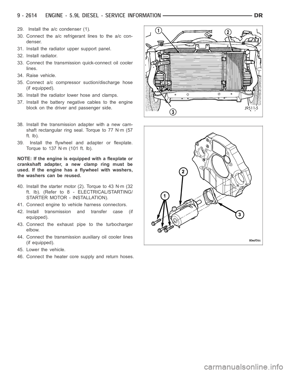
29. Install the a/c condenser (1).
30. Connect the a/c refrigerant lines to the a/c con-
denser.
31. Install the radiator upper support panel.
32. Install radiator.
33. Connect the transmission quick-connect oil cooler
lines.
34. Raise vehicle.
35. Connect a/c compressor suction/discharge hose
(if equipped).
36. Install the radiator lower hose and clamps.
37. Install the battery negative cables to the engine
block on the driver and passenger side.
38. Install the transmission adapter with a new cam-
shaft rectangular ring seal. Torque to 77 Nꞏm (57
ft. lb).
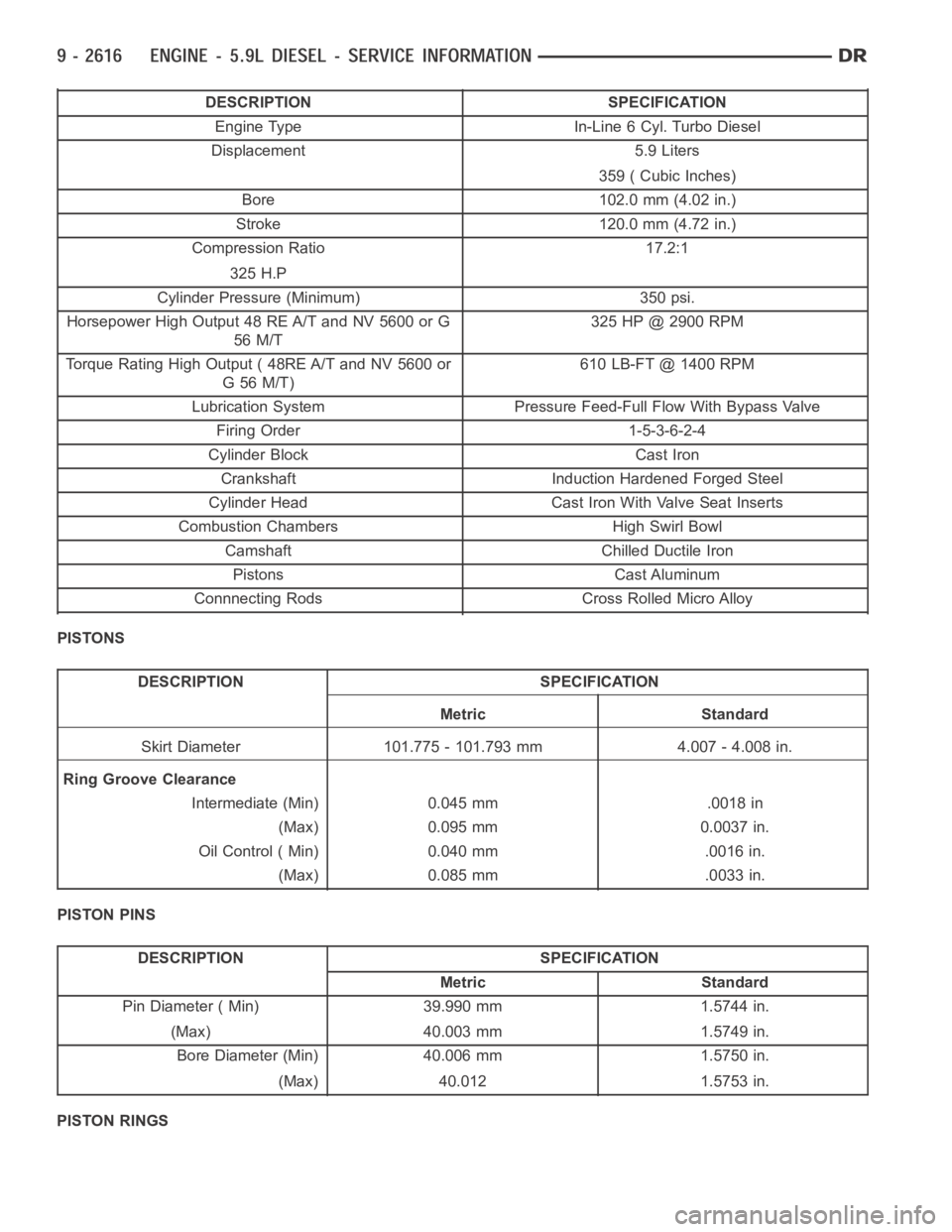
39. Install the flywheel and adapter or flexplate.
Torque to 137 Nꞏm (101 ft. lb).
NOTE: If the engine is equipped with a flexplate or
crankshaft adapter, a new clamp ring must be
used. If the engine has a flywheel with washers,
the washers can be reused.
40. Install the starter motor (2). Torque to 43 Nꞏm (32
ft. lb). (Refer to 8 - ELECTRICAL/STARTING/
STARTER MOTOR - INSTALLATION).
41. Connect engine to vehicle harness connectors.
42. Install transmission and transfer case (if
equipped).
43. Connect the exhaust pipe to the turbocharger
elbow.
44. Connect the transmission auxiliary oil cooler lines
(if equipped).
45. Lower the vehicle.
46. Connect the heater core supply and return hoses.
Page 1925 of 5267

DESCRIPTION SPECIFICATION
Engine Type In-Line 6 Cyl. Turbo Diesel
Displacement 5.9 Liters
359 ( Cubic Inches)
Bore 102.0 mm (4.02 in.)
Stroke 120.0 mm (4.72 in.)
Compression Ratio 17.2:1
325 H.P
Cylinder Pressure (Minimum) 350 psi.
Horsepower High Output 48 RE A/T and NV 5600 or G
56 M/T325 HP @ 2900 RPM
Torque Rating High Output ( 48RE A/T and NV 5600 or
G56M/T)610 LB-FT @ 1400 RPM
Lubrication System Pressure Feed-Full Flow With Bypass Valve
Firing Order 1-5-3-6-2-4
Cylinder Block Cast Iron
Crankshaft Induction Hardened Forged Steel
Cylinder Head Cast Iron With Valve Seat Inserts
Combustion Chambers High Swirl Bowl
Camshaft Chilled Ductile Iron
Pistons Cast Aluminum
Connnecting Rods Cross Rolled Micro Alloy
PISTONS
DESCRIPTION SPECIFICATION
Metric Standard
Skirt Diameter 101.775 - 101.793 mm 4.007 - 4.008 in.
Ring Groove Clearance
Intermediate (Min) 0.045 mm .0018 in
(Max) 0.095 mm 0.0037 in.
Oil Control ( Min) 0.040 mm .0016 in.
(Max) 0.085 mm .0033 in.
PISTON PINS
DESCRIPTION SPECIFICATION
Metric Standard
Pin Diameter ( Min) 39.990 mm 1.5744 in.
(Max) 40.003 mm 1.5749 in.
Bore Diameter (Min) 40.006 mm 1.5750 in.
(Max) 40.012 1.5753 in.
PISTON RINGS
Page 1929 of 5267
Compression Test Adapter - 9007
Engine Lift Bracket - 9009
Fuel Injector Remover - 9010
FUEL BLOCKOFF PLUG - 9011
FUEL TEST FITTING - 9013
Fuel Injector Tube (Connector) Remover - 9015
TURBO TEST ADAPTER - 9022
Page 1930 of 5267
ENGINE DATA PLATE
DESCRIPTION
The engine data plate contains specific information
that is helpful to servicing and obtaining parts for the
engine. The data plate is on the cylinder head cover.
Information that can be found on the data plate
includes:
Engine Part Number
Date of Engine Manufacture
Engine Serial Number
Control Parts List (CPL)
Engine Rated Horsepower
Engine Firing Order
Engine Displacement
Valve Lash Reset Specifications
If the engine data plate is missing or not legible, the engine serial numberis used for engine identification. The
engine serial number is stamped on the right side of the block, on top of the oil cooler cavity.
Page 1933 of 5267

CYLINDER HEAD
DESCRIPTION
The cylinder head is constructed of cast iron and is a one piece cross flow design with four valves per cylinder. The
arrangement of two intake and two exhaust valves per cylinder allows for a centrally located injector. The cylinder
head also includes an integral intake manifold, an integral thermostat housing, and a longitudal fuel return rifle,
which exits at the rear of the head. The 24 valve design also includes integrally cast valve guides and hardened
intake and exhaust valve seat inserts.
REMOVAL
1. Disconnect battery negative cables.
2. Raise vehicle on hoist.
3. Drain engine coolant.
4. Disconnect exhaust pipe from turbocharger elbow.
5. Remove turbocharger drain tube bolts at turbocharger. Cap off ports to prevent dirt or foreign material from enter-
ing.
6. Lower vehicle.
7. Disconnect air inlet temperature/pressure sensor.
8. Remove air cleaner housing and snorkel from the vehicle. Cap off turbocharger air inlet to prevent intrusion of
dirt or foreign material.
9. Disconnect cab heater core supply and return hoses from the cylinder head and heater pipe.
10. Disconnect turbocharger oil supply line at the turbocharger end. Cap off open ports to prevent intrusion of dirt
or foreign material.
11. Remove exhaust manifold-to-cylinder head bolts, spacers, heat shield, retention straps, and cab heater plumb-
ing. Remove exhaust manifold and turbocharger from the vehicle as an assembly.
12. Remove cooling fan/drive/shroud assembly. (Refer to 7 - COOLING/ENGINE/RADIATOR FAN - REMOVAL)
13. Remove accessory drive belt (Refer to 7 - COOLING/ACCESSORY DRIVE/DRIVE BELTS - REMOVAL).
14. Remove cooling fan support from cylinder block.
15. Remove upper generator bolt, loosen lower generator bolt, and rotate generator away from cylinder head.
16. Disconnect radiator upper hose from the thermostat housing.
17. Disconnect the Intake Air Temperature/Manifold Air Pressure, and Coolant Temperature sensor connectors.
18. Remove the engine harness to cylinder head attaching bolts and P-clipsat front of head.
19. Remove the intake air grid heater wires from the grid heater.
20. Remove engine oil level indicator tube attaching bolt at fuel filter housing bracket and inlet air connection..
21. Remove the charge air cooler-to-air inlet housing pipe.
22. Remove the engine wire harness attaching bolt and wire harness push-infastener from air inlet housing.
23. Remove the air inlet housing and intake grid heater from the intake manifold cover.
24. Remove the two grid heater harness-to-cylinder head attaching bolts at front of cylinder head.
NOTE: Extreme care should be used to keep dirt/debris from entering the fuel lines. Plastic caps should be
used on the ends of the fuel lines.
25.Remove the high pressure pump to fuel rail fuel line as follows:
a. Loosen fuel line nuts at fuel pump and at fuel rail.
b. Use a back-up wrench on the fitting at the fuel pump to keep it from loosening.
26. Remove the fuel rail to cylinder head fuel lines as follows:
a. Loosen No. 6 high pressure fuel line shield and position out of way.
b. Loosen the fuel line nuts at the fuel rail and at the cylinder head. Use a back-up wrench on HPC nut.
c. Remove the fuel line bracket bolts at the intake manifold cover.
Page 1935 of 5267

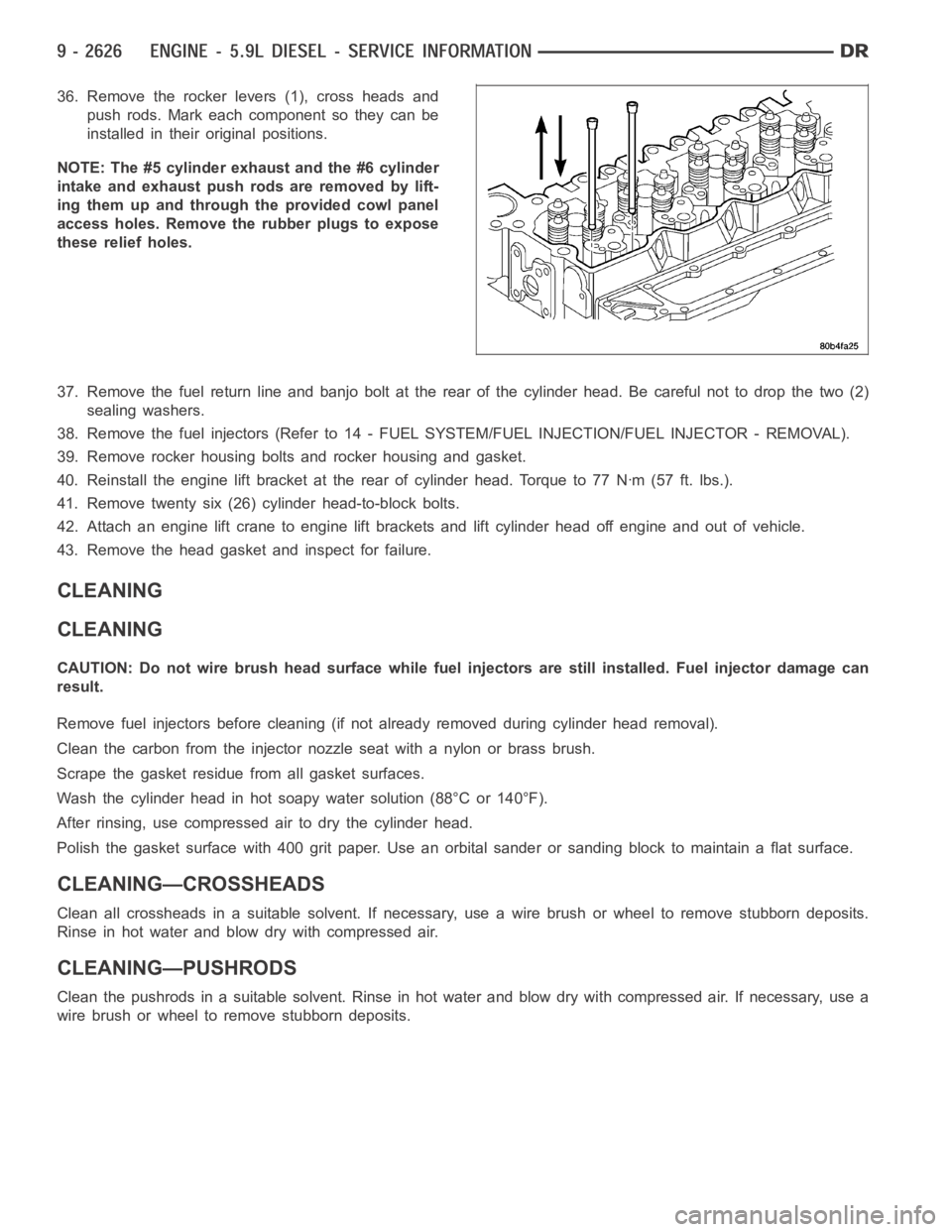
36. Remove the rocker levers (1), cross heads and
push rods. Mark each component so they can be
installed in their original positions.
NOTE: The #5 cylinder exhaust and the #6 cylinder
intake and exhaust push rods are removed by lift-
ing them up and through the provided cowl panel
access holes. Remove the rubber plugs to expose
these relief holes.
37. Remove the fuel return line and banjo bolt at the rear of the cylinder head. Be careful not to drop the two (2)
sealing washers.
38. Remove the fuel injectors (Refer to 14 - FUEL SYSTEM/FUEL INJECTION/FUEL INJECTOR - REMOVAL).
39. Remove rocker housing bolts and rocker housing and gasket.
40. Reinstall the engine lift bracket at the rear of cylinder head. Torque to77Nꞏm(57ft.lbs.).
41. Remove twenty six (26) cylinder head-to-block bolts.
42. Attach an engine lift crane to engine lift brackets and lift cylinder head off engine and out of vehicle.
43. Remove the head gasket and inspect for failure.
CLEANING
CLEANING
CAUTION: Do not wire brush head surface while fuel injectors are still installed. Fuel injector damage can
result.
Remove fuel injectors before cleaning (if not already removed during cylinder head removal).
Clean the carbon from the injector nozzle seat with a nylon or brass brush.
Scrape the gasket residuefrom all gasket surfaces.
Wash the cylinder head in hot soapy water solution (88°C or 140°F).
After rinsing, use compressed air to dry the cylinder head.
Polish the gasket surface with 400 grit paper. Use an orbital sander or sanding block to maintain a flat surface.
CLEANING—CROSSHEADS
Clean all crossheads in a suitable solvent. If necessary, use a wire brush or wheel to remove stubborn deposits.
Rinse in hot water and blow dry with compressed air.
CLEANING—PUSHRODS
Clean the pushrods in a suitable solvent. Rinse in hot water and blow dry with compressed air. If necessary, use a
wire brush or wheel to remove stubborn deposits.