2006 DODGE RAM SRT-10 check oil
[x] Cancel search: check oilPage 3208 of 5267
11 .CHECK THE WIRING AND CONNECTORS
Turn the ignition off to the lock position.
Remove the Ignition Switch Feed fuse from the TIPM.
CAUTION: Removal of the Ignition Switch Feed fuse from the TIPM will prevent the vehicle from being
startedingear.
WARNING: The Ignition Switch Feed fuse must be removed from the TIPM. Failure to do so can result in
personal injury or death.
Remove the Line Pressure Adapter, Miller tool #8259 and 0-300 psi Test Gauge, Miller tool #C-3293-SP.
Install the Transmission Simulator, Miller tool #8333.
On the Transmission Simulator, turn the Pressure Switch selector switch to2C.
Ignition on, engine not running.
With the scan tool, monitor the 2C Pressure Switch state while pressing andholding the Pressure Switch test button
and wiggling the wire harness and connectors that pertain to the 2C PressureSwitch.
Did the 2C Pressure Switch state change to closed and remain closed while wiggling the wires?
Ye s>>
Go To 12
No>>
Go To 14
12.CHECK FOR EXCESSIVE DEBRIS
Turn the ignition off to the lock position.
Remove the Transmission Simulator, Miller tool #8333.
Remove and inspect the Transmission Oil Pan per the Service Information.
Does the Transmission Oil Pan contain excessive debris or contamination?
Ye s>>
Repair the cause of the excessive debris in the Transmission Oil Pan. Referto the Service Information
for the proper procedures.
Perform 45RFE/545RFE TRANSMISSION VERIFICATION TEST - VER 1. (Refer to 21- TRANSMIS-
SION/TRANSAXLE/AUTOMATIC - 45RFE/545RFE - STANDARD PROCEDURE)
No>>
Go To 13
13.CHECK THE 2C HYDRAULIC CLUTCH CIRCUIT
Remove the Valve Body and air check the 2C clutch hydraulic circuit, in the 2C/4C clutch retainer, for leakage per
the Service Information.
NOTE: The 2C hydraulic clutch circuit contains a small bleed orifice, a small amount of air leakage is nor-
mal.
Was there excessive air leakage noticed during the air check?
Ye s>>
Repair as necessary. Check the 2C clutch piston, piston seals and bleed orifice assembly.
Perform 45RFE/545RFE TRANSMISSION VERIFICATION TEST - VER 1. (Refer to 21- TRANSMIS-
SION/TRANSAXLE/AUTOMATIC - 45RFE/545RFE - STANDARD PROCEDURE)
No>>
Disassemble and inspect the Valve Body and repair as necessary. Inspect the 2C Accumulator piston
and seals. Check for an extra check ball downstream from the #7 check ball pocket and repair as nec-
essary. If no problems are found in the Valve Body, replace the Transmission Solenoid/TRS Assembly
per the Service Information.
Perform 45RFE/545RFE TRANSMISSION VERIFICATION TEST - VER 1. (Refer to 21- TRANSMIS-
SION/TRANSAXLE/AUTOMATIC - 45RFE/545RFE - STANDARD PROCEDURE)
Page 3210 of 5267
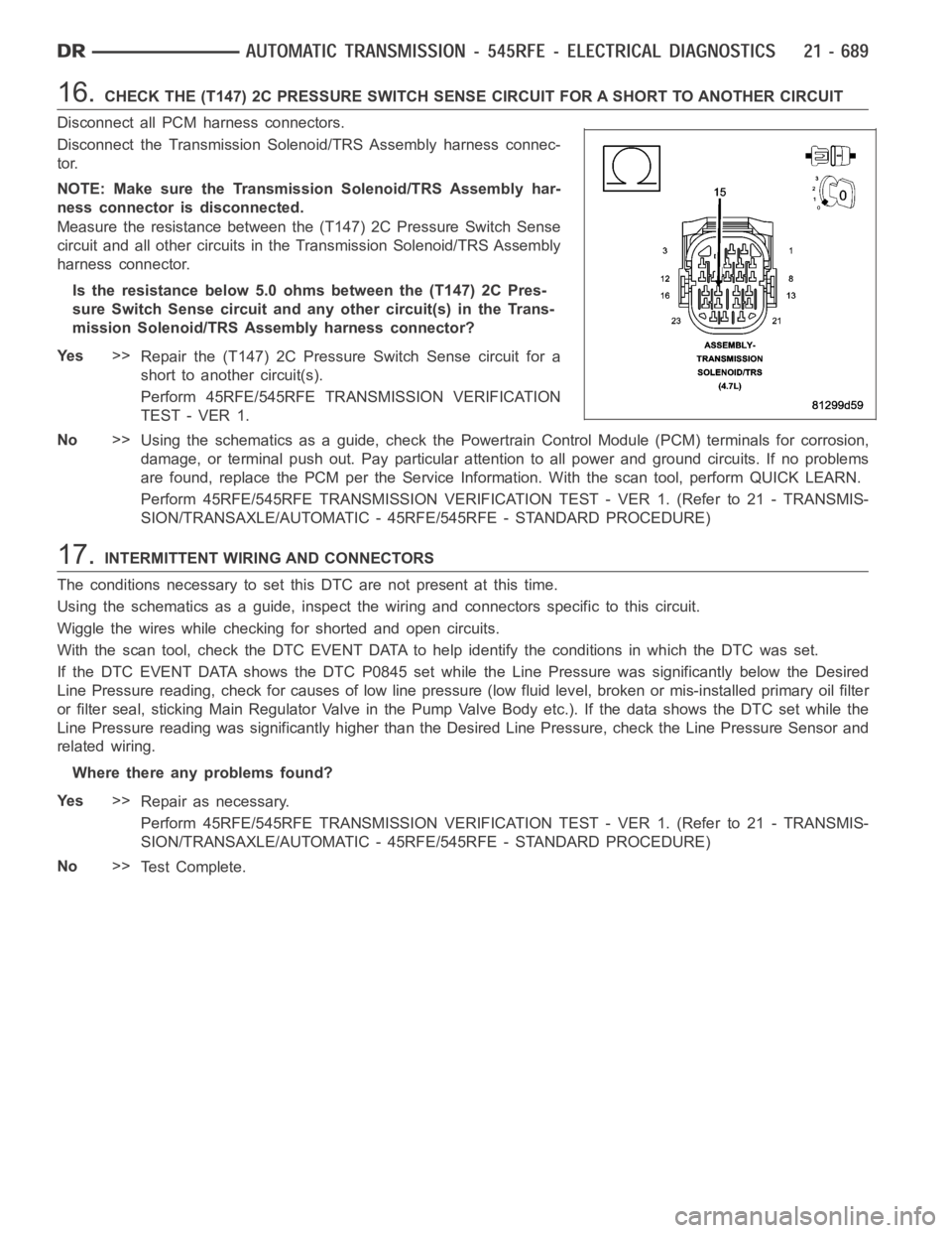
16.CHECK THE (T147) 2C PRESSURE SWITCH SENSE CIRCUIT FOR A SHORT TO ANOTHER CIRCUIT
Disconnect all PCM harness connectors.
Disconnect the Transmission Solenoid/TRS Assembly harness connec-
tor.
NOTE: Make sure the Transmission Solenoid/TRS Assembly har-
ness connector is disconnected.
Measure the resistance between the (T147) 2C Pressure Switch Sense
circuit and all other circuits in the Transmission Solenoid/TRS Assembly
harness connector.
Is the resistance below 5.0 ohms between the (T147) 2C Pres-
sure Switch Sense circuit and any other circuit(s) in the Trans-
mission Solenoid/TRS Assembly harness connector?
Ye s>>
Repair the (T147) 2C Pressure Switch Sense circuit for a
short to another circuit(s).
Perform 45RFE/545RFE TRANSMISSION VERIFICATION
TEST - VER 1.
No>>
Using the schematics as a guide, check the Powertrain Control Module (PCM)terminals for corrosion,
damage, or terminal push out. Pay particular attention to all power and ground circuits. If no problems
are found, replace the PCM per the Service Information. With the scan tool,perform QUICK LEARN.
Perform 45RFE/545RFE TRANSMISSION VERIFICATION TEST - VER 1. (Refer to 21- TRANSMIS-
SION/TRANSAXLE/AUTOMATIC - 45RFE/545RFE - STANDARD PROCEDURE)
17.INTERMITTENT WIRING AND CONNECTORS
The conditions necessary to set this DTC are not present at this time.
Using the schematics as a guide, inspect the wiring and connectors specifictothiscircuit.
Wiggle the wires while checking for shorted and open circuits.
With the scan tool, check the DTC EVENT DATA to help identify the conditionsin which the DTC was set.
If the DTC EVENT DATA shows the DTC P0845 set while the Line Pressure was significantly below the Desired
Line Pressure reading, check for causes of low line pressure (low fluid level, broken or mis-installed primary oil filter
or filter seal, sticking Main Regulator Valve in the Pump Valve Body etc.).IfthedatashowstheDTCsetwhilethe
Line Pressure reading was significantly higher than the Desired Line Pressure, check the Line Pressure Sensor and
related wiring.
Where there any problems found?
Ye s>>
Repair as necessary.
Perform 45RFE/545RFE TRANSMISSION VERIFICATION TEST - VER 1. (Refer to 21- TRANSMIS-
SION/TRANSAXLE/AUTOMATIC - 45RFE/545RFE - STANDARD PROCEDURE)
No>>
Te s t C o m p l e t e .
Page 3212 of 5267
When Monitored:
Continuously with the ignition on, engine running, with the transmissionin gear.
Set Condition:
The DTC is set if the 2C Pressure Switchreadsopenorclosedatthewrongtimein a given gear.
Possible Causes
RELATED TIPM TCM DTCS PRESENT
(T147) 2C PRESSURE SWITCH SENSE CIRCUIT OPEN
(T147) 2C PRESSURE SWITCH SENSE CIRCUIT SHORT TO GROUND
(T147) 2C PRESSURE SWITCH SENSE CIRCUIT SHORT TO OTHER CIRCUITS
EXCESSIVE FLUID LEAKAGE IN 2C CLUTCH CIRCUIT
NO. 5 AND/OR NO. 7 CHECK BALL CUT OR DAMAGED
EXTRA CHECK BALL DOWNSTREAM OF THE NO. 7 CHECK BALL SOCKET
LOW LINE PRESSURE
TRANSMISSION SOLENOID/TRS ASSEMBLY
POWERTRAIN CONTROL MODULE
WIRING AND CONNECTORS
Always perform the 45RFE/545RFE Pre-Diagnostic Troubleshooting Procedure before proceeding. (Refer to
21 - TRANSMISSION/TRANSAXLE/AUTOMATIC - 45RFE/545RFE - STANDARD PROCEDURE)
Theory of Operation
The Transmission system uses five pressure switches to monitor the fluid pressure in the LR, 2C, 4C, UD, and OD
clutch circuits. The pressure switches are continuously monitored for the correct states in each gear as shown.
GEAR L/R 2C 4C UD OD
REVERSEOPEN OPEN OPEN OPEN OPEN
P/NCLOSED** OPEN OPEN OPEN OPEN
1STCLOSED* OPEN OPEN CLOSED OPEN
2NDOPEN CLOSED OPEN CLOSED OPEN
2ND PRIMEOPEN OPEN CLOSED CLOSED OPEN
3RDOPEN OPEN OPEN CLOSED CLOSED
4THOPEN OPEN CLOSED OPEN CLOSED
5THOPEN CLOSED OPEN OPEN CLOSED
*L/R is closed if output speed is below 100 rpm in Drive and Manual 2. L/R is closed in Manual 1.
**May be open when rolling in Neutral or at low oil temperatures.
Diagnostic Test
1.CHECK FOR TCM TIPM DTCS
With the scan tool under TIPM, check for TCM Power Input DTCs.
Are there any TIPM TCM Power Input DTCs present?
Ye s>>
Refer to the Transmission category and perform the appropriate symptom. (Refer to 21 - TRANSMIS-
SION/TRANSAXLE/AUTOMATIC - 45RFE/545RFE - DIAGNOSIS AND TESTING)
No>>
Go To 2
Page 3213 of 5267
2.CHECK IF THE DTC DATA SHOWS THE CURRENT DTC
With the scan tool, check the DTC EVENT DATA.
Does the DTC EVENT DATA show data for DTC P0846?
Ye s>>
Go To 3
No>>
Refer to the Transmission category and perform the appropriate symptom shown in the DTC EVENT
DATA.
Perform 45RFE/545RFE TRANSMISSION VERIFICATION TEST - VER 1. (Refer to 21- TRANSMIS-
SION/TRANSAXLE/AUTOMATIC - 45RFE/545RFE - STANDARD PROCEDURE)
3.CHECK IF MULTIPLE DTCS ARE PRESENT
With the scan tool, check for other transmission DTC’s.
Are there two or more related pressure switch rationality DTCs present in addition to P0846?
Ye s>>
Go To 4
No>>
Go To 7
4.CHECK IF ALL THE PRESSURE SWITCHES READ CLOSED
With the scan tool, check the DTC EVENT DATA for P0846.
NOTE: Make sure to record all DTC EVENT DATA stored in the scan tool for future reference in this test
procedure.
Do all the pressure switches read CLOSED in the DTC EVENT DATA for P0846?
Ye s>>
Refer to Transmission category and perform diagnostics for P0888.
No>>
Go To 5
5.CHECK IF ALL THE PRESSURE SWITCHES READ OPEN
In the DTC EVENT DATA recorded earlier,read the state of all pressure switches.
Do all the pressure switches read OPEN?
Ye s>>
Go To 6
No>>
Go To 7
6.CHECK FOR LOW LINE PRESSURE
In the DTC EVENT DATA recorded earlier,compare the Line Pressure and the Desired Line Pressure.
Is the Line Pressure less than 40 psi, and significantly below the Desired Line Pressure?
Ye s>>
Repair as necessary to correct low line pressure. Check fluid level and adjustasnecessary.Iffluidlevel
is OK, check the Primary Oil Filter seal for a split, crack, or improperly installed. If the filter and seal are
OK, check the Main Regulator Valve in the Oil Pump. Refer to the Service Information for the above
procedures.
Perform 45RFE/545RFE TRANSMISSION VERIFICATION TEST - VER 1. (Refer to 21- TRANSMIS-
SION/TRANSAXLE/AUTOMATIC - 45RFE/545RFE - STANDARD PROCEDURE)
No>>
Replace the Transmission Solenoid/TRS Assembly per the Service Information. (Refer to 21 - TRANS-
MISSION/TRANSAXLE/AUTOMATIC - 45RFE/545RFE/TRANS SOLENOID/TRS ASSY -REMOVAL)
Perform 45RFE/545RFE TRANSMISSION VERIFICATION TEST - VER 1. (Refer to 21- TRANSMIS-
SION/TRANSAXLE/AUTOMATIC - 45RFE/545RFE - STANDARD PROCEDURE)
Page 3214 of 5267
7.CHECK IF THE DTC SET IN PARK, NEUTRAL, OR REVERSE
With the scan tool, check the DTC EVENT DATA for P0846.
NOTE: Make sure to record all DTC EVENT DATA stored in the scan tool for future reference in this test
procedure.
Does the DTC EVENT DATA show the DTC P0846 set in Park, Neutral, or Reverse?
Ye s>>
Go To 12
No>>
Go To 8
8.CHECK IF THE 2C PRESSURE SWITCH READS CLOSED
With the scan tool, check the DTC EVENT DATA for P0846.
Does the DTC EVENT DATA show the 2C Pressure Switch reading CLOSED?
Ye s>>
Go To 10
No>>
Go To 9
9.CHECK THE LINE PRESSURE
In the DTC EVENT DATA recorded earlier,compare the Line Pressure and the Desired Line Pressure.
Is the Line Pressure less than 40 psi, and significantly below the Desired Line Pressure?
Ye s>>
Repair as necessary to correct low line pressure. Check fluid level and adjustasnecessary.Iffluidlevel
is OK, check the Primary Oil Filter seal for a split, crack, or improperly installed. If the filter and seal are
OK, check the Main Regulator Valve in the Oil Pump. Refer to the Service Information for the above
procedures.
Perform 45RFE/545RFE TRANSMISSION VERIFICATION TEST - VER 1. (Refer to 21- TRANSMIS-
SION/TRANSAXLE/AUTOMATIC - 45RFE/545RFE - STANDARD PROCEDURE)
No>>
Go To 15
10.CHECK THE PCM AND WIRING
Turn the ignition off to the lock position.
Remove the Ignition Switch Feed fuse from the TIPM.
CAUTION: Removal of the Ignition Switch Feed fuse from the TIPM will prevent the vehicle from being
startedingear.
WARNING: The Ignition Switch Feed fuse must be removed from the TIPM. Failure to do so can result in
personal injury or death.
Install the Transmission Simulator, Miller tool #8333.
Ignition on, engine not running.
With the Transmission Simulator, turn the Pressure Switch selector switchtothe2Cposition.
With the scan tool, monitor the 2C Pressure Switch while pressing the Pressure Switch test button on the Trans-
mission Simulator.
Did the state of the 2C Pressure Switch change while pressing the Pressure Switch Test button?
Ye s>>
Go To 11
No>>
Go To 12
Page 3217 of 5267
15.CHECK IF THE #5 AND/OR #7 CHECK BALL IS CUT OR DAMAGED
Turn the Ignition off to the lock position.
Remove the Valve Body Assembly per the Service Information.
Inspect the #5 and #7 check balls for any cuts or damage.
Inspect the 2C accumulator piston and seals and also the 2C tower seal on topof the valve body. Refer to the
Service Information.
Where there any problems found?
Ye s>>
Repair as necessary. Check for excessive clutch debris in the transmission oil pan. If excessive clutch
debris is present, repair 2C clutch as necessary. Refer to the Service Information for proper repair pro-
cedures.
Perform 45RFE/545RFE TRANSMISSION VERIFICATION TEST - VER 1. (Refer to 21- TRANSMIS-
SION/TRANSAXLE/AUTOMATIC - 45RFE/545RFE - STANDARD PROCEDURE)
No>>
Go To 16
16.CHECK FOR EXCESSIVE FLUID LEAKAGE WITHIN THE 2C CLUTCH CIRCUIT
Air check the 2C Clutch hydraulic circuit. Refer to the Service Information.
NOTE: This hydraulic clutch circuit contains a small bleed orifice. Smallleakage is considered normal.
Was there excessive air leakage in the 2C Clutch hydraulic circuit?
Ye s>>
Repair as necessary. Refer to the Service Information.
Perform 45RFE/545RFE TRANSMISSION VERIFICATION TEST - VER 1.
No>>
Replace the Transmission Solenoid/TRS Assembly per the Service Information. (Refer to 21 - TRANS-
MISSION/TRANSAXLE/AUTOMATIC - 45RFE/545RFE/TRANS SOLENOID/TRS ASSY -REMOVAL)
Perform 45RFE/545RFE TRANSMISSION VERIFICATION TEST - VER 1. (Refer to 21- TRANSMIS-
SION/TRANSAXLE/AUTOMATIC - 45RFE/545RFE - STANDARD PROCEDURE)
Page 3219 of 5267
When Monitored:
Continuously while driving in a forward gear.
Set Condition:
The PCM continuously monitors Actual Line Pressure and compares it to DesiredLinePressure.IftheActual
Line Pressure is more than 10 psi below Desired Line Pressure, this DTC willset.
Possible Causes
CHECK FOR RELATED DTC’S
LOW FLUID LEVEL
(F856) 5-VOLT SUPPLY CIRCUIT OPEN
POOR LINE PRESSURE SENSOR CONNECTION
(F856) 5-VOLT SUPPLY CIRCUIT SHORT TO GROUND
(F856) 5-VOLT SUPPLY CIRCUIT SHORT TO VOLTAGE
(T118) PRESSURE CONTROL SOLENOID CONTROL CIRCUIT SHORT TO ANOTHER CIRCUIT
INTERNAL TRANSMISSION
LINE PRESSURE SENSOR
CRACKED, PLUGGED, OR MISINSTALLED PRIMARY OIL FILTER
STUCK OR STICKING MAIN REGULATOR VALVE
POWERTRAIN CONTROL MODULE
Always perform the 45RFE/545RFE Pre-Diagnostic Troubleshooting Procedure before proceeding. (Refer to
21 - TRANSMISSION/TRANSAXLE/AUTOMATIC - 45RFE/545RFE - STANDARD PROCEDURE)
Theory of Operation
Line pressure is measured by the Line Pressure Sensor (LPS) and regulationis achieved by changing the duty
cycle of the Pressure Control Solenoid (PCS) controlled by the Transmission Control System. (5% duty cycle =
solenoid off = Max line pressure, 62%duty cycle = solenoid on = Min line pressure). The Transmission Control
System calculates the desired line pressure based on inputs from both the engine and transmission.
The Transmission Control System calculates torque input to the transmission and uses it as the primary input to the
desired line pressure calculation. This is called Torque Based Line Pressure. In addition, the line pressure is set to
a preset level 827 or 931kPa (120 or 135 psi) during shifts and in Park and Neutral to ensure consistent shift qual-
ity. The desired line pressure is continuously being compared to the actual line pressure. If the actual line pressure
is consistently lower than the target while driving, the line pressure lowDTC P0868 will set.
Diagnostic Test
1.CHECKFORRELATEDDTCS
With the scan tool, check for other transmission DTCs
Is the DTC P0932 present also?
Ye s>>
Refer to the Transmission category and perform the appropriate symptom.
No>>
Go To 2
Page 3221 of 5267
5.CHECK THE LINE PRESSURE SENSOR
Turn the ignition off to the lock position.
Disconnect the Transmission Simulator, Miller tool #8333 and reconnect all previously disconnected connectors.
Install the Line Pressure Adaptor, Miller tool #8259, and the Pressure Gauge, Miller tool #C-3293, 0 to 2000 kPa or
0to300psi.
Start the engine in park.
Monitor the line pressure readings of both the scan tool and the pressure gauge and compare the two readings.
Is the line pressure gauge reading within 34 kPa or 5 psi of the scan tool reading?
Ye s>>
Go To 6
No>>
Replace the Line Pressure Sensor per the Service Information.
Perform 45RFE/545RFE TRANSMISSION VERIFICATION TEST - VER 1. (Refer to 21- TRANSMIS-
SION/TRANSAXLE/AUTOMATIC - 45RFE/545RFE - STANDARD PROCEDURE)
6.CHECK FOR A PLUGGED TRANSMISSION OIL FILTER
Turn the ignition off to the lock position.
Remove and inspect the Transmission Oil Pan for excessive debris per the Service Information.
Remove and inspect the Primary Oil Filter per the Service Information.
NOTE: Make sure the Primary Transmission Oil Filter and/or O-ring is not cracked or split.
Does the Oil Pan contain excessive debris and/or is the Primary Oil Filter cracked or plugged?
Ye s>>
Repair the plugged, cracked, or split Primary Transmission Oil Filter and/or O-ring. If the Primary Trans-
mission Oil Filter is plugged refer to the Service Information for the proper Hydraulic repair procedure.
Perform 45RFE/545RFE TRANSMISSION VERIFICATION TEST - VER 1. (Refer to 21- TRANSMIS-
SION/TRANSAXLE/AUTOMATIC - 45RFE/545RFE - STANDARD PROCEDURE)
No>>
Repair internal transmission and inspect the Transmission Oil Pump per the Service Information and
replace if necessary. If no problem is found, replace the Solenoid/TRS Assembly.
Perform 45RFE/545RFE TRANSMISSION VERIFICATION TEST - VER 1. (Refer to 21- TRANSMIS-
SION/TRANSAXLE/AUTOMATIC - 45RFE/545RFE - STANDARD PROCEDURE)
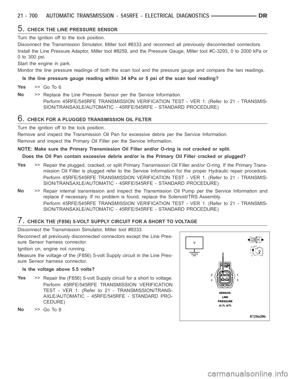
7.CHECK THE (F856) 5-VOLT SUPPLY CIRCUIT FOR A SHORT TO VOLTAGE
Disconnect the Transmission Simulator, Miller tool #8333.
Reconnect all previously disconnected connectors except the Line Pres-
sure Sensor harness connector.
Ignition on, engine not running.
Measure the voltage of the (F856) 5-volt Supply circuit in the Line Pres-
sure Sensor harness connector.
Is the voltage above 5.5 volts?
Ye s>>
Repair the (F856) 5-volt Supply circuit for a short to voltage.
Perform 45RFE/545RFE TRANSMISSION VERIFICATION
TEST - VER 1. (Refer to 21 - TRANSMISSION/TRANS-
AXLE/AUTOMATIC - 45RFE/545RFE - STANDARD PRO-
CEDURE)
No>>
Go To 8