2006 DODGE RAM SRT-10 spark plugs
[x] Cancel search: spark plugsPage 2032 of 5267
material also will prevent corrosion. MoparGasket Sealant is available in a 13 oz. aerosol can or 4 oz./16 oz. can
w/applicator.
FORM-IN-PLACE GASKET AND SEALER APPLICATION
MoparGasket Maker material should be applied sparingly 1 mm (0.040 in.) diameter or less of sealant to one
gasket surface. Be certain the material surrounds each mounting hole. Excess material can easily be wiped off.
Components should be torqued in place within 15 minutes. The use of a locating dowel is recommended during
assembly to prevent smearing material off the location.
Mopar
Engine RTV GEN II or ATF RTV gasket material should be applied in a continuous bead approximately 3
mm (0.120 in.) in diameter. All mounting holes must be circled. For corner sealing,a3.17mmor6.35mm(1/8in.
or 1/4 in.) drop is placed in the center of the gasket contact area. Uncured sealant may be removed with a shop
towel. Components should be torqued in place while the sealant is still wettothetouch(within10minutes).The
usage of a locating dowel is recommended during assembly to prevent smearing material off the location.
Mopar
Gasket Sealant in an aerosol can should be applied using a thin, even coat sprayed completely over both
surfaces to be joined, and both sides of a gasket. Then proceed with assembly. Material in a can w/applicator can
be brushed on evenly over the sealing surfaces. Material in an aerosol can shouldbeusedonengineswithmulti-
layer steel gaskets.
ENGINE GASKET SURFACE PREPARATION
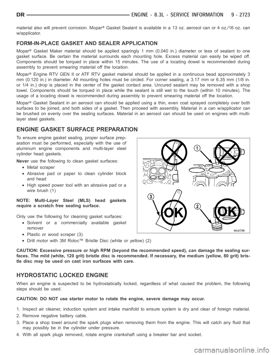
To ensure engine gasket sealing, proper surface prep-
aration must be performed, especially with the use of
aluminum engine components and multi-layer steel
cylinder head gaskets.
Neveruse the following to clean gasket surfaces:
Metal scraper
Abrasive pad or paper to clean cylinder block
and head
High speed power tool with an abrasive pad or a
wire brush (1)
NOTE: Multi-Layer Steel (MLS) head gaskets
require a scratch free sealing surface.
Only use the following for cleaning gasket surfaces:
Solvent or a commercially available gasket
remover
Plastic or wood scraper (3)
Drill motor with 3M Roloc™ Bristle Disc (white or yellow) (2)
CAUTION: Excessive pressure or high RPM (beyond the recommended speed), can damage the sealing sur-
faces. The mild (white, 120 grit) bristle disc is recommended. If necessary, the medium (yellow, 80 grit) bris-
tle disc may be used on cast iron surfaces with care.
HYDROSTATIC LOCKED ENGINE
When an engine is suspected to be hydrostatically locked, regardless of what caused the problem, the following
steps should be used.
CAUTION: DO NOT use starter motor to rotate the engine, severe damage may occur.
1. Inspect air cleaner, induction system and intake manifold to ensure system is dry and clear of foreign material.
2. Remove negative battery cable.
3. Place a shop towel around the spark plugs when removing them from the engine. This will catch any fluid that
may possibly be in the cylinder under pressure.
4. With all spark plugs removed, rotate engine crankshaft using a breaker bar and socket.
Page 2033 of 5267
5. Identify the fluid in the cylinder(s) (i.e., coolant, fuel, oil or other).
6. Make sure all fluid has been removed from the cylinders. Inspect engine for damage (i.e., connecting rods, pis-
tons, valves, etc.)
7. Repair engine or components as necessary to prevent this problem from re-occurring.
CAUTION: Squirt approximately one teaspoon of oil into the cylinders, rotateenginetolubricatethecylin-
der walls to prevent damage on restart.
8. Install new spark plugs.
9. Drain engine oil and remove oil filter.
10. Fill engine with specified amount of approved oil and install new oil filter.
11. Connect negative battery cable.
12. Start engine and check for any leaks.
REMOVAL - ENGINE ASSEMBLY
1. Perform fuel pressure release procedure (Refer to
14 - FUEL SYSTEM/FUEL DELIVERY - STAN-
DARD PROCEDURE).
2. Disconnect negative battery cable.
3. Disconnect throttle body air inlet duct, remove air
cleaner cover (Refer to 9 - ENGINE/AIR INTAKE
SYSTEM/AIR CLEANER ELEMENT - REMOVAL).
4. Raise and support the vehicle.
5. Remove the lower engine shield.
6. Drain cooling system (Refer to 7 - COOLING/EN-
GINE - STANDARD PROCEDURE - DRAINING
COOLING SYSTEM).
7. Paint mark and remove the driveshaft (Refer to 3 -
DIFFERENTIAL & DRIVELINE/PROPELLER
SHAFT/PROPELLER SHAFT - REMOVAL).
8.Removethetransmission(Referto21-TRANS-
MISSION/TRANSAXLE/MANUAL - REMOVAL).
9. Remove the starter (Refer to 8 - ELECTRICAL/
STARTING/STARTER MOTOR - REMOVAL).
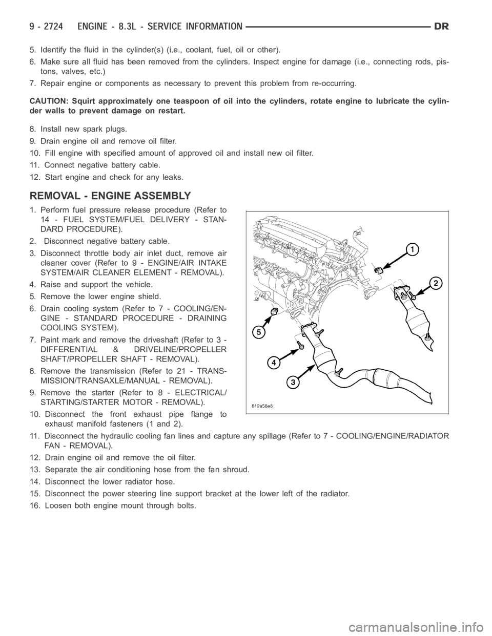
10. Disconnect the front exhaust pipe flange to
exhaust manifold fasteners (1 and 2).
11. Disconnect the hydraulic cooling fan lines and capture any spillage (Refer to 7 - COOLING/ENGINE/RADIATOR
FA N - R E M O VA L ) .
12. Drain engine oil and remove the oil filter.
13. Separate the air conditioning hose from the fan shroud.
14. Disconnect the lower radiator hose.
15. Disconnect the power steering line support bracket at the lower left ofthe radiator.
16. Loosen both engine mount through bolts.
Page 2035 of 5267
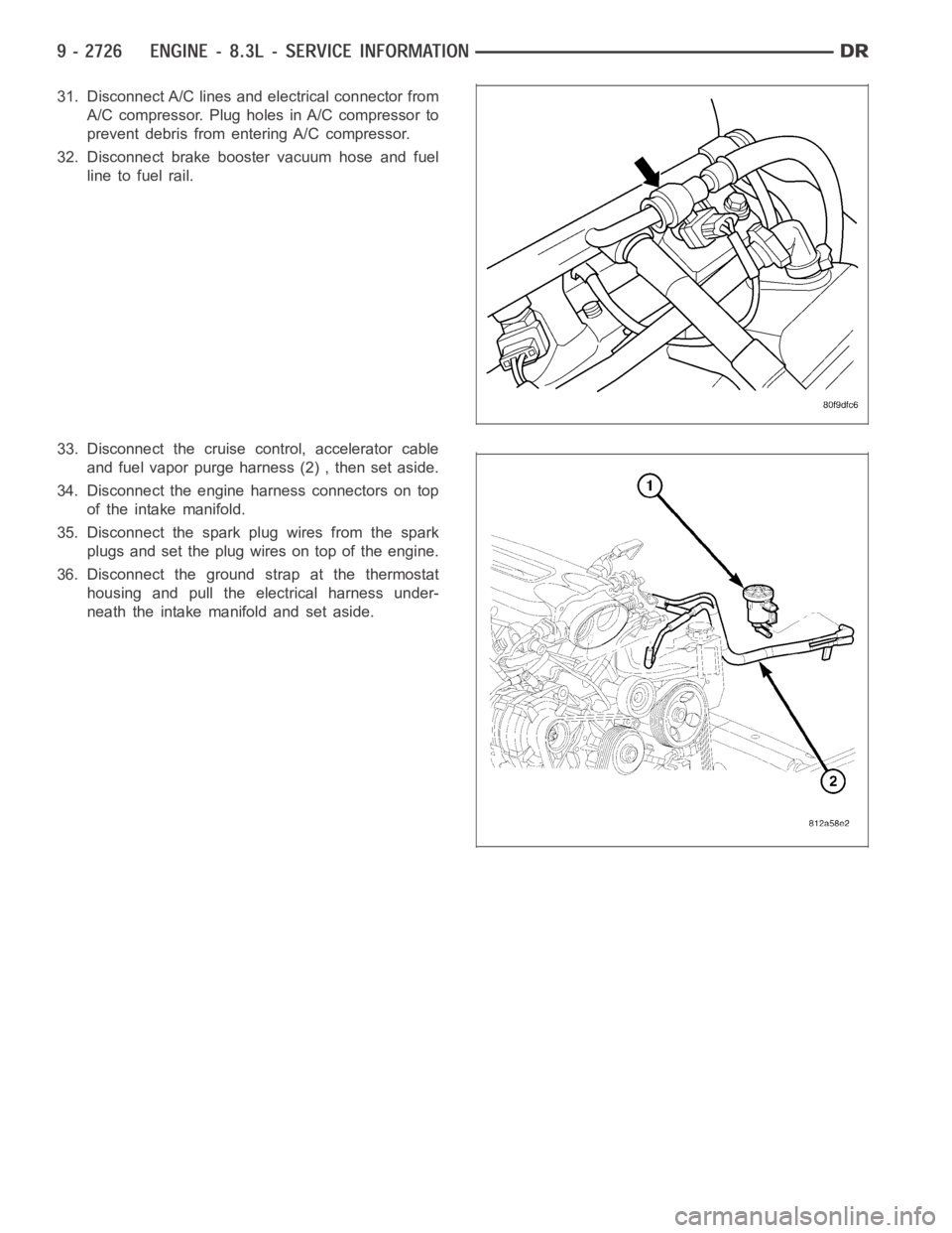
31. Disconnect A/C lines and electrical connector from
A/C compressor. Plug holes in A/C compressor to
prevent debris from entering A/C compressor.
32. Disconnect brake booster vacuum hose and fuel
line to fuel rail.
33. Disconnect the cruise control, accelerator cable
and fuel vapor purge harness (2) , then set aside.
34. Disconnect the engine harness connectors on top
of the intake manifold.
35. Disconnect the spark plug wires from the spark
plugs and set the plug wires on top of the engine.
36. Disconnect the ground strap at the thermostat
housing and pull the electrical harness under-
neath the intake manifold and set aside.
Page 2046 of 5267
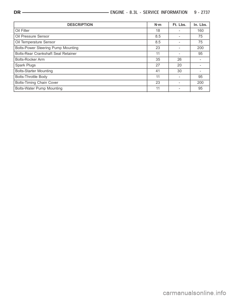
DESCRIPTION Nꞏm Ft. Lbs. In. Lbs.
Oil Filter18 - 160
Oil Pressure Sensor 8.5 - 75
Oil Temperature Sensor 8.5 - 75
Bolts-Power Steering Pump Mounting 23 - 200
Bolts-Rear Crankshaft Seal Retainer 11 - 95
Bolts-Rocker Arm 35 26 -
Spark Plugs27 20 -
Bolts-Starter Mounting 41 30 -
Bolts-Throttle Body 11 - 95
Bolts-Timing Chain Cover 23 - 200
Bolts-Water Pump Mounting 11 - 95
Page 2063 of 5267
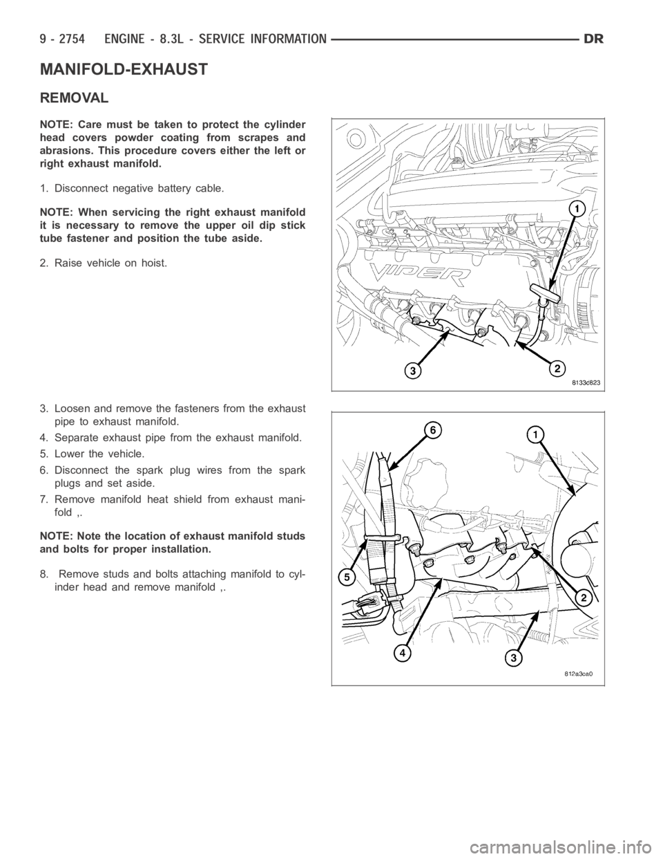
MANIFOLD-EXHAUST
REMOVAL
NOTE: Care must be taken to protect the cylinder
head covers powder coating from scrapes and
abrasions. This procedure covers either the left or
right exhaust manifold.
1. Disconnect negative battery cable.
NOTE: When servicing the right exhaust manifold
it is necessary to remove the upper oil dip stick
tube fastener and position the tube aside.
2. Raise vehicle on hoist.
3. Loosen and remove the fasteners from the exhaust
pipe to exhaust manifold.
4. Separate exhaust pipe from the exhaust manifold.
5. Lower the vehicle.
6. Disconnect the spark plug wires from the spark
plugs and set aside.
7. Remove manifold heat shield from exhaust mani-
fold ,.
NOTE: Note the location of exhaust manifold studs
and bolts for proper installation.
8. Remove studs and bolts attaching manifold to cyl-
inder head and remove manifold ,.
Page 2072 of 5267
SPRINGS/SEALS-VALVE
DIAGNOSIS AND TESTING
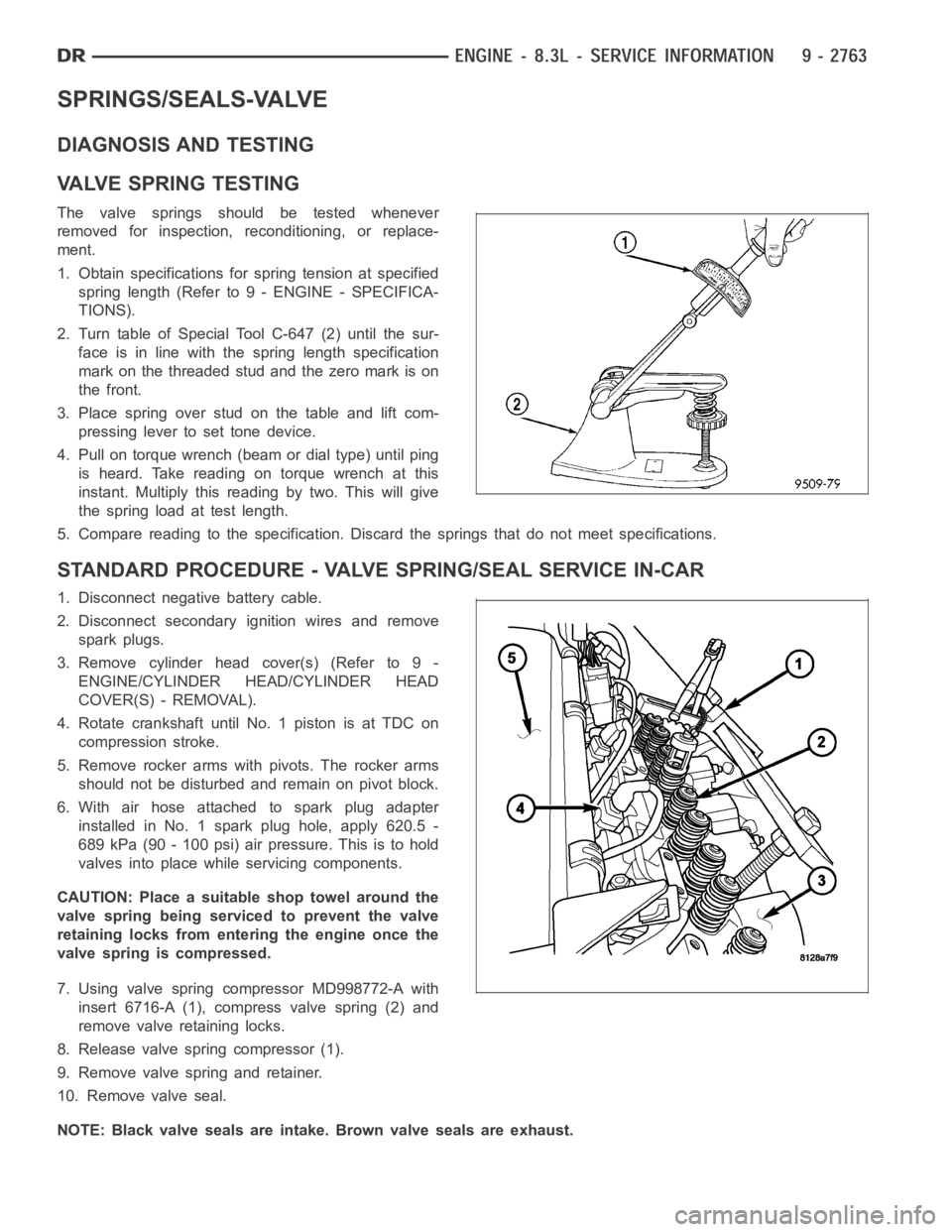
VA LV E S P R I N G T E S T I N G
The valve springs should be tested whenever
removed for inspection, reconditioning, or replace-
ment.
1. Obtain specifications for spring tension at specified
spring length (Refer to 9 - ENGINE - SPECIFICA-
TIONS).
2. Turn table of Special Tool C-647 (2) until the sur-
face is in line with the spring length specification
mark on the threaded stud and the zero mark is on
the front.
3.Placespringoverstudonthetableandliftcom-
pressing lever to set tone device.
4. Pull on torque wrench (beam or dial type) until ping
is heard. Take reading on torque wrench at this
instant. Multiply this reading by two. This will give
the spring load at test length.
5. Compare reading to the specification. Discard the springs that do not meet specifications.
STANDARD PROCEDURE - VALVE SPRING/SEAL SERVICE IN-CAR
1. Disconnect negative battery cable.
2. Disconnect secondary ignition wires and remove
spark plugs.
3. Remove cylinder head cover(s) (Refer to 9 -
ENGINE/CYLINDER HEAD/CYLINDER HEAD
COVER(S) - REMOVAL).
4. Rotate crankshaft until No. 1 piston is at TDC on
compression stroke.
5. Remove rocker arms with pivots. The rocker arms
should not be disturbed and remain on pivot block.
6. With air hose attached to spark plug adapter
installed in No. 1 spark plug hole, apply 620.5 -
689 kPa (90 - 100 psi) air pressure. This is to hold
valves into place while servicing components.
CAUTION: Place a suitable shop towel around the
valve spring being serviced to prevent the valve
retaining locks from entering the engine once the
valve spring is compressed.
7. Using valve spring compressor MD998772-A with
insert 6716-A (1), compress valve spring (2) and
remove valve retaining locks.
8. Release valve spring compressor (1).
9. Remove valve spring and retainer.
10. Remove valve seal.
NOTE: Black valve seals are intake. Brown valve seals are exhaust.
Page 2073 of 5267
11. The intake and exhaust valve stem seals should be pushed firmly and squarely over the valve guide using the
valve stem as guide. Push seal against top of guide. When installing the valve retainer locks, compress the
springonly enoughto install the locks.
CAUTION: Do not pinch seal between retainer and top of valve guide.
12. Follow the same procedure on the remaining 9 cylinders.Make sure piston is at TDC on the cylinder the
valve spring is being removed.
13. Remove spark plug adapter tool.
14. Install rocker arm and pedestal assemblies. Ensure push rods are seated properly under each rocker arm.
Tightenrockerarmboltsto35Nꞏm(26ft.lbs.).
15. Install cylinder head covers (Refer to 9 - ENGINE/CYLINDER HEAD/CYLINDERHEADCOVER(S)-INSTAL-
LATION).
16. Install spark plugs and connect secondary ignition wires.
17. Connect negative battery cable.
REMOVAL
NOTE: Before replacing parts, inspect all related
valvetrain components for damage to prevent
engine misfire.
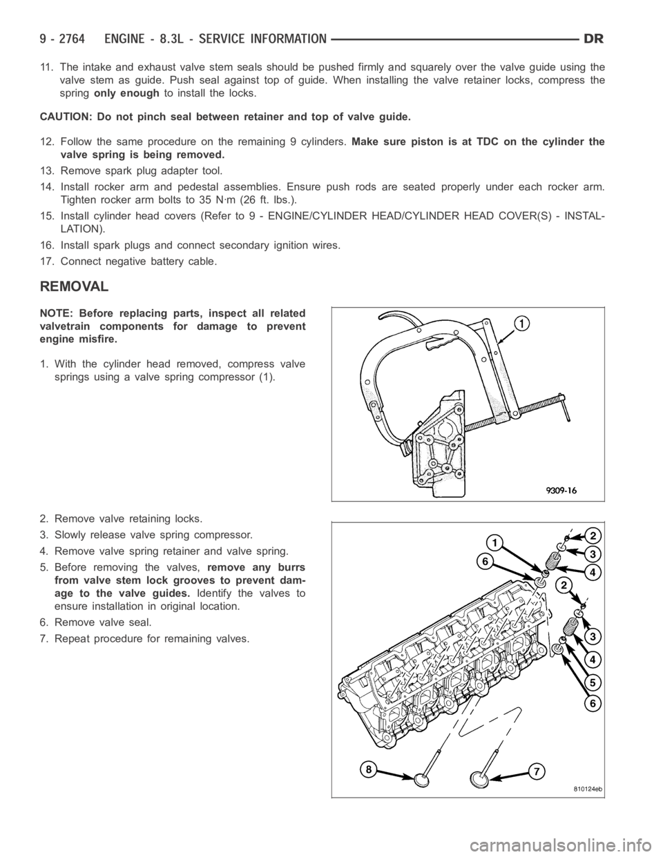
1. With the cylinder head removed, compress valve
springs using a valve spring compressor (1).
2. Remove valve retaining locks.
3. Slowly release valve spring compressor.
4. Remove valve spring retainer and valve spring.
5. Before removing the valves,remove any burrs
from valve stem lock grooves to prevent dam-
age to the valve guides.Identify the valves to
ensure installation in original location.
6. Remove valve seal.
7. Repeat procedure for remaining valves.
Page 2143 of 5267
CONVERTER-CATALYTIC
DESCRIPTION
WARNING: THE NORMAL OPERATING TEMPERATURE OF THE EXHAUST SYSTEM IS VERY HIGH. THERE-
FORE, NEVER WORK AROUND OR ATTEMPT TO SERVICE ANY PART OF THE EXHAUST SYSTEMUNTIL IT
IS COOLED. SPECIAL CARE SHOULD BE TAKEN WHEN WORKING NEAR THE CATALYTIC CONVERTER.
THE TEMPERATURE OF THE CONVERTER RISES TO A HIGH LEVEL AFTER A SHORT PERIOD OFENGINE
OPERATION TIME.
CAUTION: DO NOT remove spark plug wires from plugs or by any other means short out cylinders. Failure
of the catalytic converter can occur due to a temperature increase caused by unburned fuel passing
through the converter.
The stainless steel catalytic converter body is designed to last the life of the vehicle. Excessive heat can result in
bulging or other distortion, but excessive heat will not be the fault of theconverter. If unburned fuel enters the con-
verter, overheating may occur. If a converter is heat-damaged, correct the cause of the damage at the same time
the converter is replaced. Also, inspect all other components of the exhaust system for heat damage.
Unleaded gasoline must be used to avoid contaminating the catalyst core.
50 State emission vehicles incorporate two mini catalytic converters located after the exhaust manifolds and before
the inline catalytic converter.
OPERATION
The catalytic converter captures and burns any unburned fuel mixture exiting the combustion chambers during the
exhaust stroke of the engine. This process aids in reducing emissions output.
REMOVAL
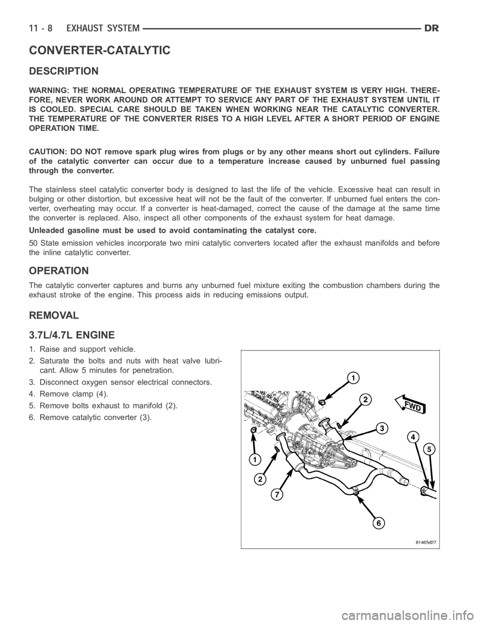
3.7L/4.7L ENGINE
1. Raise and support vehicle.
2. Saturate the bolts and nuts with heat valve lubri-
cant. Allow 5 minutes for penetration.
3. Disconnect oxygen sensor electrical connectors.
4. Remove clamp (4).
5. Remove bolts exhaust to manifold (2).
6. Remove catalytic converter (3).