2006 DODGE RAM SRT-10 spark plugs
[x] Cancel search: spark plugsPage 1765 of 5267

CONDITION POSSIBLE CAUSES CORRECTION
EXCESSIVE OIL CONSUMPTION
OR SPARK PLUGS OIL FOULED1. CCV System malfunction 1. (Refer to 25 - EMISSIONS
CONTROL/EVAPORATIVE
EMISSIONS - DESCRIPTION) for
correct operation
2. Defective valve stem seal(s) 2. Repair or replace seal(s)
3. Worn or broken piston rings 3. Hone cylinder bores. Install new
rings
4. Scuffed pistons/cylinder walls 4. Hone cylinder bores and replace
pistons as required
5. Carbon in oil control ring groove 5. Remove rings and de-carbon
piston
6. Worn valve guides 6. Inspect/replace valve guides as
necessary
7. Piston rings fitted too tightly in
grooves7. Remove rings and check ring end
gap and side clearance. Replace if
necessary
STANDARD PROCEDURE
STANDARD PROCEDURE - REPAIR DAMAGED OR WORN THREADS
CAUTION: Be sure that the tapped holes maintain the original center line.
Damaged or worn threads can be repaired. Essentially, this repair consistsof:
Drilling out worn or damaged threads.
Tapping the hole with a special Heli-Coil Tap, or equivalent.
Installing an insert into the tapped hole to bring the hole back to its original thread size.
STANDARD PROCEDURE—HYDROSTATIC LOCK
CAUTION: DO NOT use the starter motor to rotate the crankshaft. Severe damage could occur.
When an engine is suspected of hydrostatic lock (regardless of what causedthe problem), follow the steps below.
1. Perform the Fuel Pressure Release Procedure (Refer to 14 - FUEL SYSTEM/FUEL DELIVERY - STANDARD
PROCEDURE).
2. Disconnect the negative cable(s) from the battery.
3. Inspect air cleaner, induction system, and intake manifold to ensure system is dry and clear of foreign material.
4. Place a shop towel around the spark plugs to catch any fluid that may possibly be under pressure in the cylinder
head. Remove the spark plugs.
5. With all spark plugs removed, rotate the crankshaft using a breaker bar and socket.
6. Identify the fluid in the cylinders (coolant, fuel, oil, etc.).
7. Be sure all fluid has been removed from the cylinders.
8. Repair engine or components as necessary to prevent this problem from occurring again.
9. Squirt a small amount of engine oil into the cylinders to lubricate the walls. This will prevent damage on restart.
10. Install new spark plugs. Tighten the spark plugs to 41 Nꞏm (30 ft. lbs.) torque.
11. Drain engine oil. Remove and discard the oil filter.
12. Install the drain plug. Tighten the plug to 34 Nꞏm (25 ft. lbs.) torque.
13. Install a new oil filter.
14. Fill engine crankcase with the specified amount and grade of oil. (Refer to LUBRICATION & MAINTENANCE -
SPECIFICATIONS).
Page 1782 of 5267
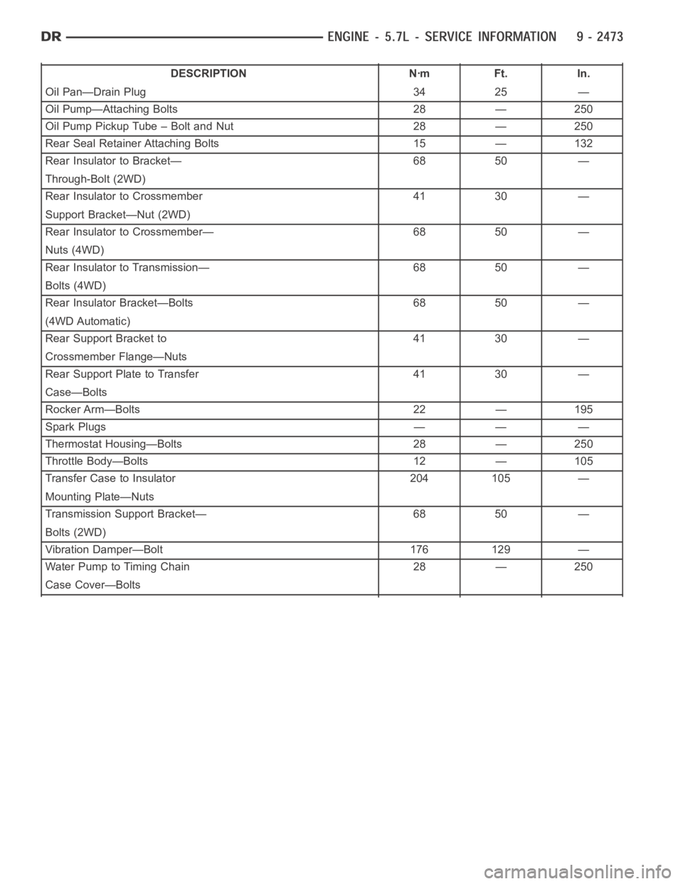
DESCRIPTION Nꞏm Ft. In.
Oil Pan—Drain Plug 34 25 —
Oil Pump—Attaching Bolts 28 — 250
Oil Pump Pickup Tube – Bolt and Nut 28 — 250
Rear Seal Retainer Attaching Bolts 15 — 132
Rear Insulator to Bracket— 68 50 —
Through-Bolt (2WD)
Rear Insulator to Crossmember 41 30 —
Support Bracket—Nut (2WD)
Rear Insulator to Crossmember— 68 50 —
Nuts (4WD)
Rear Insulator to Transmission— 68 50 —
Bolts (4WD)
Rear Insulator Bracket—Bolts 68 50 —
(4WD Automatic)
Rear Support Bracket to 41 30 —
Crossmember Flange—Nuts
Rear Support Plate to Transfer 41 30 —
Case—Bolts
Rocker Arm—Bolts 22 — 195
Spark Plugs — — —
Thermostat Housing—Bolts 28 — 250
Throttle Body—Bolts 12 — 105
Transfer Case to Insulator 204 105 —
Mounting Plate—Nuts
Transmission Support Bracket— 68 50 —
Bolts (2WD)
Vibration Damper—Bolt 176 129 —
Water Pump to Timing Chain 28 — 250
Case Cover—Bolts
Page 1796 of 5267
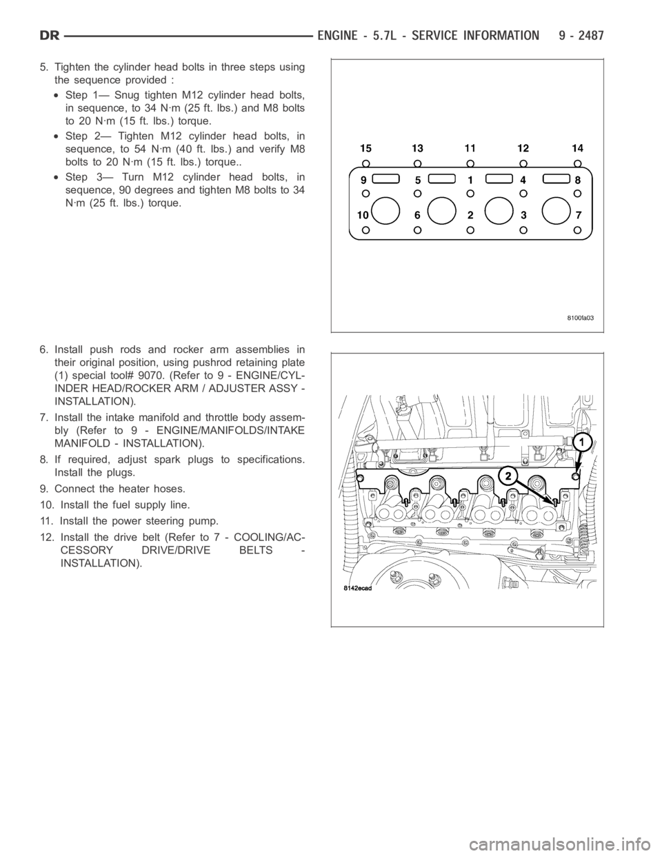
5. Tighten the cylinder head bolts in three steps using
the sequence provided :
Step 1— Snug tighten M12 cylinder head bolts,
in sequence, to 34 Nꞏm (25 ft. lbs.) and M8 bolts
to 20 Nꞏm (15 ft. lbs.) torque.
Step 2— Tighten M12 cylinder head bolts, in
sequence, to 54 Nꞏm (40 ft. lbs.) and verify M8
bolts to 20 Nꞏm (15 ft. lbs.) torque..
Step 3— Turn M12 cylinder head bolts, in
sequence, 90 degrees and tighten M8 bolts to 34
Nꞏm (25 ft. lbs.) torque.
6. Install push rods and rocker arm assemblies in
their original position, using pushrod retaining plate
(1) special tool# 9070. (Refer to 9 - ENGINE/CYL-
INDER HEAD/ROCKER ARM / ADJUSTER ASSY -
INSTALLATION).
7. Install the intake manifold and throttle body assem-
bly (Refer to 9 - ENGINE/MANIFOLDS/INTAKE
MANIFOLD - INSTALLATION).
8. If required, adjust spark plugs to specifications.
Install the plugs.
9. Connect the heater hoses.
10. Install the fuel supply line.
11. Install the power steering pump.
12. Install the drive belt (Refer to 7 - COOLING/AC-
CESSORY DRIVE/DRIVE BELTS -
INSTALLATION).
Page 1823 of 5267
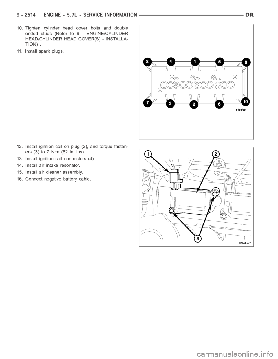
10. Tighten cylinder head cover bolts and double
ended studs (Refer to 9 - ENGINE/CYLINDER
HEAD/CYLINDER HEAD COVER(S) - INSTALLA-
TION) .
11. Install spark plugs.
12. Install ignition coil on plug (2), and torque fasten-
ers (3) to 7 Nꞏm (62 in. lbs)
13. Install ignition coil connectors (4).
14. Install air intake resonator.
15. Install air cleaner assembly.
16. Connect negative battery cable.
Page 2024 of 5267
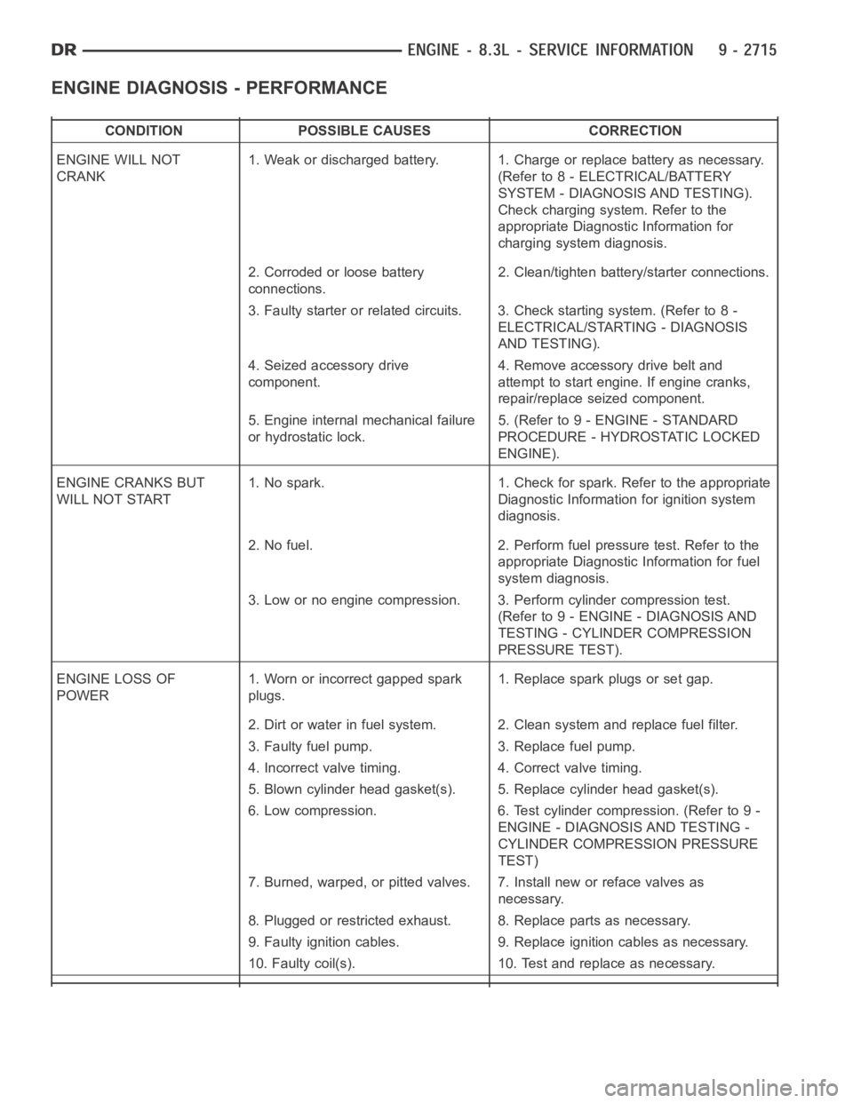
ENGINE DIAGNOSIS - PERFORMANCE
CONDITION POSSIBLE CAUSES CORRECTION
ENGINE WILL NOT
CRANK1. Weak or discharged battery. 1. Charge or replace battery as necessary.
(Refer to 8 - ELECTRICAL/BATTERY
SYSTEM - DIAGNOSIS AND TESTING).
Check charging system. Refer to the
appropriate Diagnostic Information for
charging system diagnosis.
2. Corroded or loose battery
connections.2. Clean/tighten battery/starter connections.
3. Faulty starter or related circuits. 3. Check starting system. (Refer to8-
ELECTRICAL/STARTING - DIAGNOSIS
AND TESTING).
4. Seized accessory drive
component.4. Remove accessory drive belt and
attempt to start engine. If engine cranks,
repair/replace seized component.
5. Engine internal mechanical failure
or hydrostatic lock.5. (Refer to 9 - ENGINE - STANDARD
PROCEDURE - HYDROSTATIC LOCKED
ENGINE).
ENGINE CRANKS BUT
WILL NOT START1. No spark. 1. Check for spark. Refer to the appropriate
Diagnostic Information for ignition system
diagnosis.
2. No fuel. 2. Perform fuel pressure test. Refer to the
appropriate Diagnostic Information for fuel
system diagnosis.
3. Low or no engine compression. 3. Perform cylinder compression test.
(Refer to 9 - ENGINE - DIAGNOSIS AND
TESTING - CYLINDER COMPRESSION
PRESSURE TEST).
ENGINE LOSS OF
POWER1. Worn or incorrect gapped spark
plugs.1. Replace spark plugs or set gap.
2. Dirt or water in fuel system. 2. Clean system and replace fuel filter.
3. Faulty fuel pump. 3. Replace fuel pump.
4. Incorrect valve timing. 4. Correct valve timing.
5. Blown cylinder head gasket(s). 5. Replace cylinder head gasket(s).
6. Low compression. 6. Test cylinder compression. (Refer to 9 -
ENGINE - DIAGNOSIS AND TESTING -
CYLINDER COMPRESSION PRESSURE
TEST)
7. Burned, warped, or pitted valves. 7. Install new or reface valves as
necessary.
8. Plugged or restricted exhaust. 8. Replace parts as necessary.
9. Faulty ignition cables. 9. Replace ignition cables as necessary.
10. Faulty coil(s). 10. Test and replace as necessary.
Page 2025 of 5267
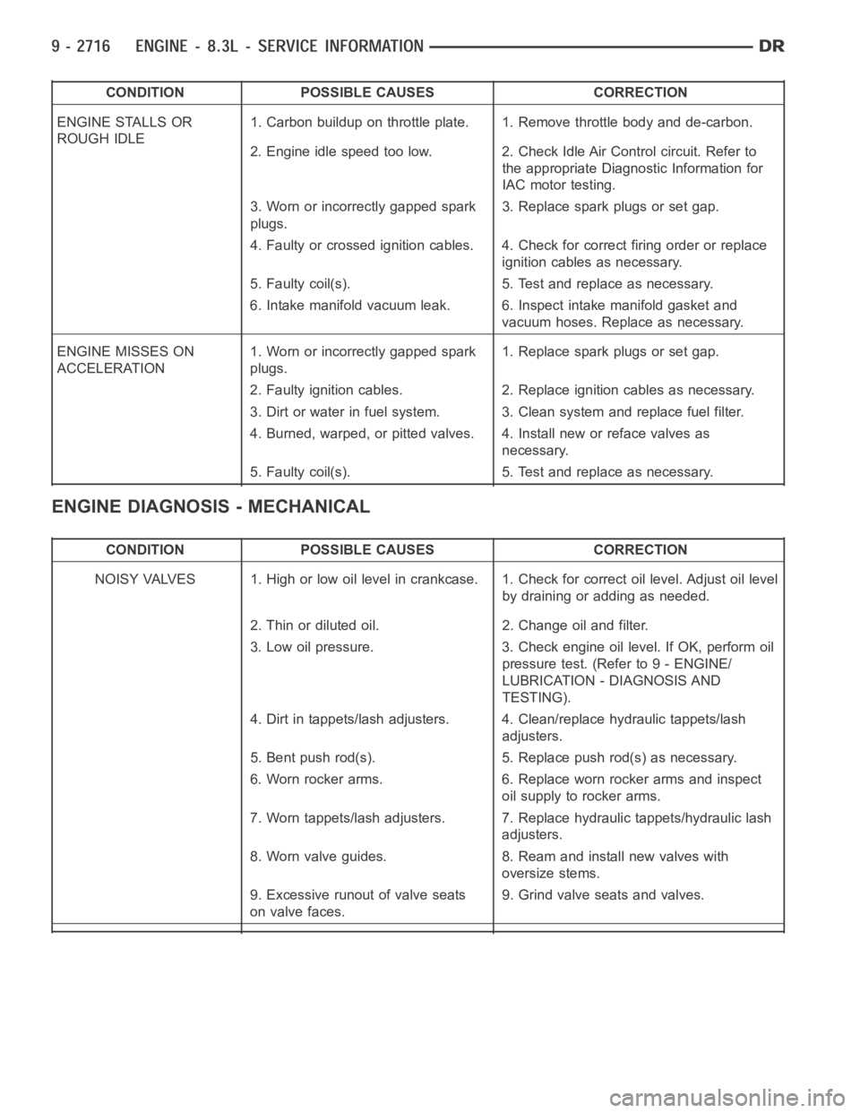
CONDITION POSSIBLE CAUSES CORRECTION
ENGINE STALLS OR
ROUGH IDLE1. Carbon buildup on throttle plate. 1. Remove throttle body and de-carbon.
2. Engine idle speed too low. 2. Check Idle Air Control circuit. Refer to
the appropriate Diagnostic Information for
IAC motor testing.
3. Worn or incorrectly gapped spark
plugs.3. Replace spark plugs or set gap.
4. Faulty or crossed ignition cables. 4. Check for correct firing order or replace
ignition cables as necessary.
5. Faulty coil(s). 5. Test and replace as necessary.
6. Intake manifold vacuum leak. 6. Inspect intake manifold gasket and
vacuum hoses. Replace as necessary.
ENGINE MISSES ON
ACCELERATION1. Worn or incorrectly gapped spark
plugs.1. Replace spark plugs or set gap.
2. Faulty ignition cables. 2. Replace ignition cables as necessary.
3. Dirt or water in fuel system. 3. Clean system and replace fuel filter.
4. Burned, warped, or pitted valves. 4. Install new or reface valves as
necessary.
5. Faulty coil(s). 5. Test and replace as necessary.
ENGINE DIAGNOSIS - MECHANICAL
CONDITION POSSIBLE CAUSES CORRECTION
NOISY VALVES 1. High or low oil level incrankcase. 1. Check for correct oil level. Adjust oil level
by draining or adding as needed.
2. Thin or diluted oil. 2. Change oil and filter.
3. Low oil pressure. 3. Check engine oil level. If OK, perform oil
pressure test. (Refer to 9 - ENGINE/
LUBRICATION - DIAGNOSIS AND
TESTING).
4. Dirt in tappets/lash adjusters. 4. Clean/replace hydraulic tappets/lash
adjusters.
5. Bent push rod(s). 5. Replace push rod(s) as necessary.
6. Worn rocker arms. 6. Replace worn rocker arms and inspect
oil supply to rocker arms.
7. Worn tappets/lash adjusters. 7. Replace hydraulic tappets/hydrauliclash
adjusters.
8. Worn valve guides. 8. Ream and install new valves with
oversize stems.
9. Excessive runout of valve seats
on valve faces.9. Grind valve seats and valves.
Page 2027 of 5267
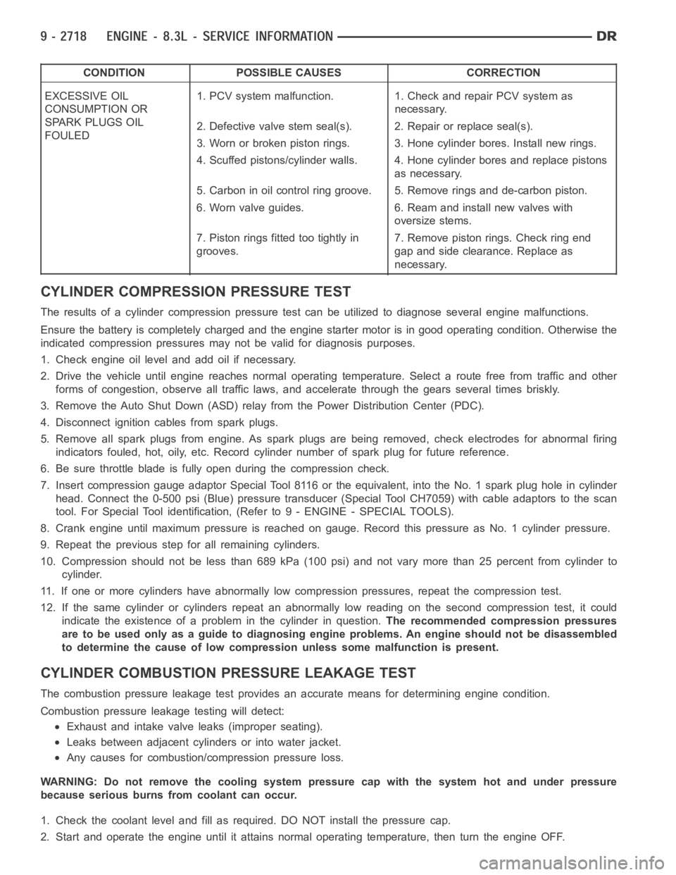
CONDITION POSSIBLE CAUSES CORRECTION
EXCESSIVE OIL
CONSUMPTION OR
SPARK PLUGS OIL
FOULED1. PCV system malfunction. 1. Check and repair PCV system as
necessary.
2. Defective valve stem seal(s). 2. Repair or replace seal(s).
3. Worn or broken piston rings. 3. Hone cylinder bores. Install new rings.
4. Scuffed pistons/cylinder walls. 4. Hone cylinder bores and replace pistons
as necessary.
5. Carbon in oil control ring groove. 5. Remove rings and de-carbon piston.
6. Worn valve guides. 6. Ream and install new valves with
oversize stems.
7. Piston rings fitted too tightly in
grooves.7. Remove piston rings. Check ring end
gap and side clearance. Replace as
necessary.
CYLINDER COMPRESSION PRESSURE TEST
The results of a cylinder compressionpressure test can be utilized to diagnose several engine malfunctions.
Ensurethebatteryiscompletelychargedandtheenginestartermotorisingood operating condition. Otherwise the
indicated compression pressures may not be valid for diagnosis purposes.
1. Check engine oil level and add oil if necessary.
2. Drive the vehicle until engine reaches normal operating temperature. Select a route free from traffic and other
forms of congestion, observe all traffic laws, and accelerate through thegears several times briskly.
3. Remove the Auto Shut Down (ASD) relay from the Power Distribution Center(PDC).
4. Disconnect ignition cables from spark plugs.
5. Remove all spark plugs from engine. As spark plugs are being removed, check electrodes for abnormal firing
indicators fouled, hot, oily, etc. Record cylinder number of spark plug for future reference.
6. Be sure throttle blade is fully open during the compression check.
7. Insert compression gauge adaptor Special Tool 8116 or the equivalent, into the No. 1 spark plug hole in cylinder
head. Connect the 0-500 psi (Blue) pressure transducer (Special Tool CH7059) with cable adaptors to the scan
tool. For Special Tool identification, (Refer to 9 - ENGINE - SPECIAL TOOLS).
8. Crank engine until maximum pressure is reached on gauge. Record this pressure as No. 1 cylinder pressure.
9. Repeat the previous step for all remaining cylinders.
10. Compression should not be less than 689 kPa (100 psi) and not vary more than 25 percent from cylinder to
cylinder.
11. If one or more cylinders have abnormally low compression pressures, repeat the compression test.
12. If the same cylinder or cylinders repeat an abnormally low reading on the second compression test, it could
indicate the existence of a problem in the cylinder in question.The recommended compression pressures
are to be used only as a guide to diagnosing engine problems. An engine should not be disassembled
to determine the cause of low compression unless some malfunction is present.
CYLINDER COMBUSTIONPRESSURE LEAKAGE TEST
The combustion pressure leakage test provides an accurate means for determining engine condition.
Combustion pressure leakage testing will detect:
Exhaust and intake valve leaks (improper seating).
Leaks between adjacent cylinders or into water jacket.
Any causes for combustion/compression pressure loss.
WARNING: Do not remove the cooling system pressure cap with the system hot and under pressure
because serious burns from coolant can occur.
1. Check the coolant level and fill as required. DO NOT install the pressurecap.
2. Start and operate the engine until it attains normal operating temperature, then turn the engine OFF.
Page 2028 of 5267
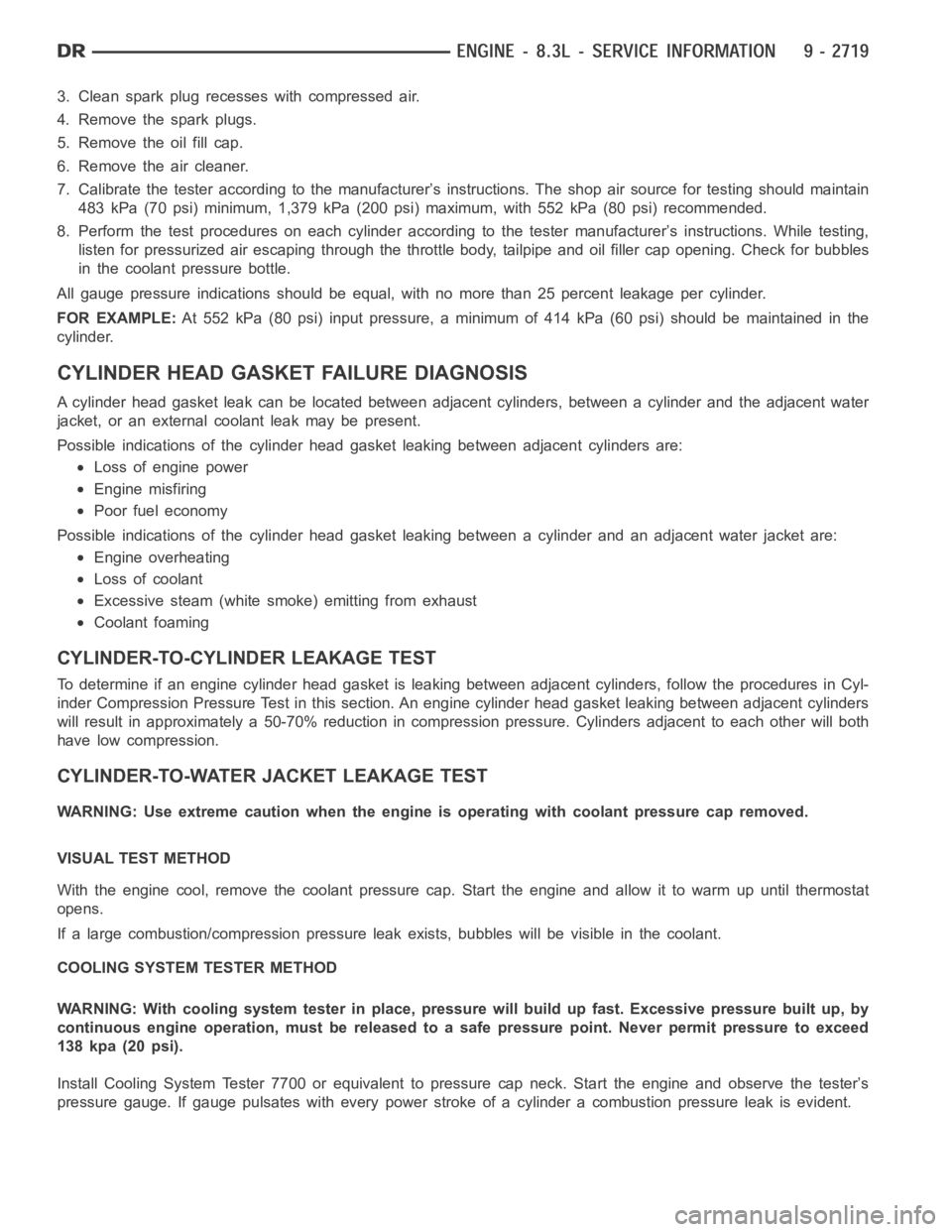
3. Clean spark plug recesses with compressed air.
4. Remove the spark plugs.
5. Remove the oil fill cap.
6. Remove the air cleaner.
7. Calibrate the tester according to the manufacturer’s instructions. The shop air source for testing should maintain
483 kPa (70 psi) minimum, 1,379 kPa (200 psi) maximum, with 552 kPa (80 psi) recommended.
8. Perform the test procedures on each cylinder according to the tester manufacturer’s instructions. While testing,
listen for pressurized air escaping through the throttle body, tailpipe and oil filler cap opening. Check for bubbles
in the coolant pressure bottle.
All gauge pressure indications should be equal, with no more than 25 percent leakage per cylinder.
FOR EXAMPLE:At 552 kPa (80 psi) input pressure, a minimum of 414 kPa (60 psi) should be maintained in the
cylinder.
CYLINDER HEAD GASKET FAILURE DIAGNOSIS
A cylinder head gasket leak can be located between adjacent cylinders, between a cylinder and the adjacent water
jacket, or an external coolant leak may be present.
Possible indications of the cylinder head gasket leaking between adjacent cylinders are:
Loss of engine power
Engine misfiring
Poor fuel economy
Possible indications of the cylinder head gasket leaking between a cylinder and an adjacent water jacket are:
Engine overheating
Loss of coolant
Excessive steam (white smoke) emitting from exhaust
Coolant foaming
CYLINDER-TO-CYLINDER LEAKAGE TEST
To determine if an engine cylinder head gasket is leaking between adjacentcylinders, follow the procedures in Cyl-
inder Compression Pressure Test in this section. An engine cylinder head gasket leaking between adjacent cylinders
will result in approximately a 50-70% reduction in compression pressure.Cylinders adjacent to each other will both
have low compression.
CYLINDER-TO-WATER JACKET LEAKAGE TEST
WARNING: Use extreme caution when the engine is operating with coolant pressure cap removed.
VISUAL TEST METHOD
With the engine cool, remove the coolant pressure cap. Start the engine andallow it to warm up until thermostat
opens.
If a large combustion/compression pressure leak exists, bubbles will be visible in the coolant.
COOLING SYSTEM TESTER METHOD
WARNING: With cooling system tester in place, pressure will build up fast.Excessive pressure built up, by
continuous engine operation, must be released to a safe pressure point. Never permit pressure to exceed
138 kpa (20 psi).
Install Cooling System Tester 7700 or equivalent to pressure cap neck. Start the engine and observe the tester’s
pressure gauge. If gauge pulsates with every power stroke of a cylinder a combustion pressure leak is evident.