Page 1614 of 5267

COVER-TIMING
REMOVAL
1. Disconnect the battery negative cable.
2. Drain cooling system (Refer to 7 - COOLING -
STANDARD PROCEDURE).
3. Remove electric cooling fan and fan shroud assem-
bly.
4. Remove fan and fan drive assembly (Refer to 7 -
COOLING/ENGINE/FAN DRIVE VISCOUS
CLUTCH - REMOVAL).
5. Disconnect both heater hoses at timing cover.
6. Disconnect lower radiator hose at engine.
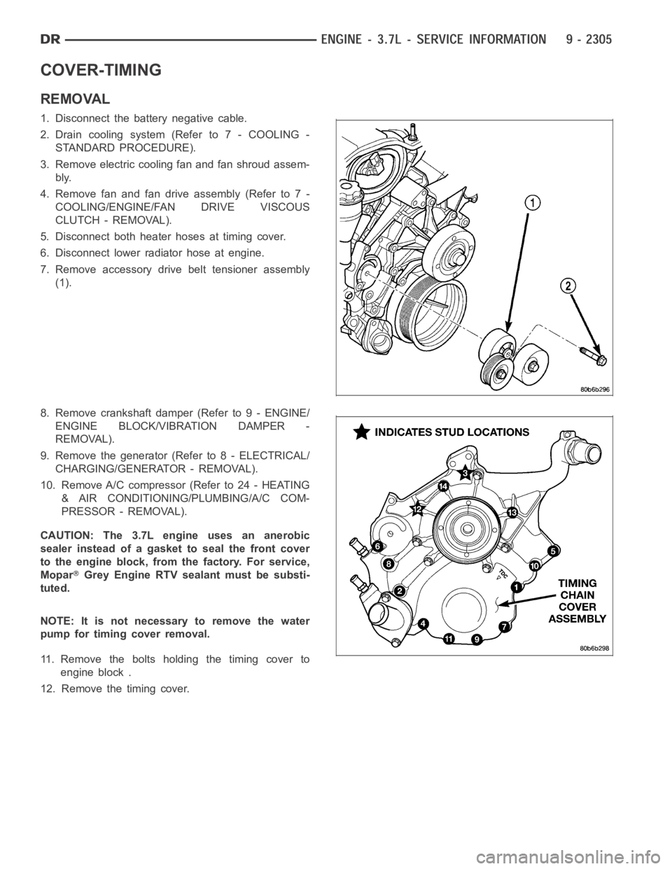
7. Remove accessory drive belt tensioner assembly
(1).
8. Remove crankshaft damper (Refer to 9 - ENGINE/
ENGINE BLOCK/VIBRATION DAMPER -
REMOVAL).
9. Remove the generator (Refer to 8 - ELECTRICAL/
CHARGING/GENERATOR - REMOVAL).
10. Remove A/C compressor (Refer to 24 - HEATING
& AIR CONDITIONING/PLUMBING/A/C COM-
PRESSOR - REMOVAL).
CAUTION: The 3.7L engine uses an anerobic
sealer instead of a gasket to seal the front cover
to the engine block, from the factory. For service,
Mopar
Grey Engine RTV sealant must be substi-
tuted.
NOTE: It is not necessary to remove the water
pump for timing cover removal.
11. Remove the bolts holding the timing cover to
engine block .
12. Remove the timing cover.
Page 1615 of 5267

INSTALLATION
CAUTION: Do not use oil based liquids to clean
timing cover or block surfaces. Use only rubbing
alcohol, along with plastic or wooden scrapers.
Use no wire brushes or abrasive wheels or metal
scrapers, or damage to surfaces could result.
1. Clean timing chain cover and block surface using
rubbing alcohol.
CAUTION: The 3.7L uses a special anerobic sealer
instead of a gasket to seal the timing cover to the
engine block, from the factory. For service repairs,
Mopar
Engine Grey RTV must be used as a sub-
stitute.
2. Inspect the water passage o-rings for any damage,
and replace as necessary.
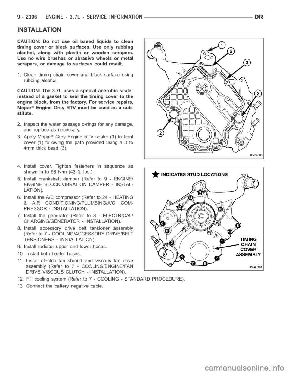
3. Apply Mopar
Grey Engine RTV sealer (3) to front
cover(1)followingthepathprovidedusinga3to
4mm thick bead (3).
4. Install cover. Tighten fasteners in sequence as
showninto58Nꞏm(43ft.lbs.).
5. Install crankshaft damper (Refer to 9 - ENGINE/
ENGINE BLOCK/VIBRATION DAMPER - INSTAL-
LATION).
6. Install the A/C compressor (Refer to 24 - HEATING
& AIR CONDITIONING/PLUMBING/A/C COM-
PRESSOR - INSTALLATION).
7. Install the generator (Refer to 8 - ELECTRICAL/
CHARGING/GENERATOR - INSTALLATION).
8. Install accessory drive belt tensioner assembly
(Refer to 7 - COOLING/ACCESSORY DRIVE/BELT
TENSIONERS - INSTALLATION).
9. Install radiator upper and lower hoses.
10. Install both heater hoses.
11. Install electric fan shroud and viscous fan drive
assembly (Refer to 7 - COOLING/ENGINE/FAN
DRIVE VISCOUS CLUTCH - INSTALLATION).
12. Fill cooling system (Refer to 7 - COOLING - STANDARD PROCEDURE).
13. Connect the battery negative cable.
Page 1633 of 5267
27. Remove generator (3) (Refer to 8 - ELECTRICAL/
CHARGING/GENERATOR - REMOVAL).
28. Disconnect the two heater hoses from the timing
chain cover and heater core.
29. Unclip (2) and remove heater hoses (1) and tubes
from the intake manifold.
Page 1638 of 5267
12. Position and install heater hoses (1) and tubes
onto intake manifold.
13. Install the heater hoses onto the heater core and
the engine front cover, and install clips (2).
14. Install generator (3) (Refer to 8 - ELECTRICAL/
CHARGING/GENERATOR - INSTALLATION).
15. Install A/C condenser (Refer to 24 - HEATING & AIR CONDITIONING/PLUMBING/A/C CONDENSER - INSTAL-
LATION), radiator (Refer to 7 - COOLING/ENGINE/RADIATOR - INSTALLATION)and transmission oil cooler.
16. Connect radiator upper and lower hoses.
17. Connect the transmission oil cooler lines to the radiator.
18. Install accessory drive belt (Refer to 7 - COOLING/ACCESSORY DRIVE/DRIVE BELTS - INSTALLATION), fan
assembly and shroud (Refer to 7 - COOLING/ENGINE/FAN DRIVE VISCOUS CLUTCH- INSTALLATION).
Page 1768 of 5267
11. Remove generator assembly (2) (Refer to 8 -
ELECTRICAL/CHARGING/GENERATOR -
REMOVAL).
12. Remove the intake manifold and IAFM as an
assembly (Refer to 9 - ENGINE/MANIFOLDS/IN-
TAKE MANIFOLD - REMOVAL).
13. Disconnect the heater hoses.
NOTE: It is not necessary to disconnect P/S hoses
from pump, for P/S pump removal.
14. Remove the power steering pump and set aside.
15. Disconnect the fuel supply line (Refer to 14 -
FUEL SYSTEM/FUEL DELIVERY/QUICK CON-
NECT FITTING - STANDARD PROCEDURE).
16. Raise and support the vehicle on a hoist and
drain the engine oil.
17. Remove engine front mount thru-bolt nuts.
18. Remove right side axle retaining bolts.
19. Disconnect the transmission oil cooler lines from
their retainers at the oil pan bolts.
20. Disconnect exhaust pipe at manifolds (2).
Page 1774 of 5267
17. Install the intake manifold.
18. Using a new gasket, install throttle body (Refer to
14 - FUEL SYSTEM/FUEL INJECTION/THROT-
TLE BODY - INSTALLATION).
19. Install the generator (2) and wire connections
(Refer to 8 - ELECTRICAL/CHARGING/GENERA-
TOR - INSTALLATION).
20. Install a/c compressor (2) (Refer to 24 - HEATING
& AIR CONDITIONING/PLUMBING/A/C COM-
PRESSOR - INSTALLATION).
Page 2024 of 5267

ENGINE DIAGNOSIS - PERFORMANCE
CONDITION POSSIBLE CAUSES CORRECTION
ENGINE WILL NOT
CRANK1. Weak or discharged battery. 1. Charge or replace battery as necessary.
(Refer to 8 - ELECTRICAL/BATTERY
SYSTEM - DIAGNOSIS AND TESTING).
Check charging system. Refer to the
appropriate Diagnostic Information for
charging system diagnosis.
2. Corroded or loose battery
connections.2. Clean/tighten battery/starter connections.
3. Faulty starter or related circuits. 3. Check starting system. (Refer to8-
ELECTRICAL/STARTING - DIAGNOSIS
AND TESTING).
4. Seized accessory drive
component.4. Remove accessory drive belt and
attempt to start engine. If engine cranks,
repair/replace seized component.
5. Engine internal mechanical failure
or hydrostatic lock.5. (Refer to 9 - ENGINE - STANDARD
PROCEDURE - HYDROSTATIC LOCKED
ENGINE).
ENGINE CRANKS BUT
WILL NOT START1. No spark. 1. Check for spark. Refer to the appropriate
Diagnostic Information for ignition system
diagnosis.
2. No fuel. 2. Perform fuel pressure test. Refer to the
appropriate Diagnostic Information for fuel
system diagnosis.
3. Low or no engine compression. 3. Perform cylinder compression test.
(Refer to 9 - ENGINE - DIAGNOSIS AND
TESTING - CYLINDER COMPRESSION
PRESSURE TEST).
ENGINE LOSS OF
POWER1. Worn or incorrect gapped spark
plugs.1. Replace spark plugs or set gap.
2. Dirt or water in fuel system. 2. Clean system and replace fuel filter.
3. Faulty fuel pump. 3. Replace fuel pump.
4. Incorrect valve timing. 4. Correct valve timing.
5. Blown cylinder head gasket(s). 5. Replace cylinder head gasket(s).
6. Low compression. 6. Test cylinder compression. (Refer to 9 -
ENGINE - DIAGNOSIS AND TESTING -
CYLINDER COMPRESSION PRESSURE
TEST)
7. Burned, warped, or pitted valves. 7. Install new or reface valves as
necessary.
8. Plugged or restricted exhaust. 8. Replace parts as necessary.
9. Faulty ignition cables. 9. Replace ignition cables as necessary.
10. Faulty coil(s). 10. Test and replace as necessary.
Page 2080 of 5267

25. Remove A/C compressor mounting bolts. Reposi-
tion A/C compressor.Do notdisconnect A/C lines.
26. Disconnect the power steering line support
bracket at the radiator.
27. Lower the vehicle.
28. Remove the upper radiator hose and coolant
recovery container.
29. Remove the cooling fan module (Refer to 7 -
COOLING/ENGINE/RADIATOR FAN -
REMOVAL).
30. Remove the upper idler pulley.
31. Remove power steering pump mounting bolts.
Reposition power steering pump aside.Do not
disconnect power steering lines.
32. Remove the generator (Refer to 8 - ELECTRI-
CAL/CHARGING/GENERATOR - REMOVAL).
33. Disconnect the heater hose at the timing cover.
34. Disconnect the ground wire at the thermostat
housing.
NOTE: Do Not remove the camshaft position sensor from the timing cover.
35. Disconnect the camshaft sensor wiring harness connector.
36. Disconnect engine coolant temperature (ECT) sensor connector.
37. Remove crankshaft pulley and damper (Refer to 9 - ENGINE/ENGINE BLOCK/VIBRATION DAMPER -
REMOVAL).
38. Remove the timing cover.
INSTALLATION
CAUTION: Do not use a metal scraper to clean alu-
minum sealing surfaces, as damage to surfaces
may occur. Use only a plastic scraper and Mopar
Brake Parts Cleaner or the equivalent.
1. Be sure mating surfaces of chain case cover and
cylinder block are clean and free from burrs.
Crankshaft oil seal must be removed to insure cor-
rect oil pump engagement.
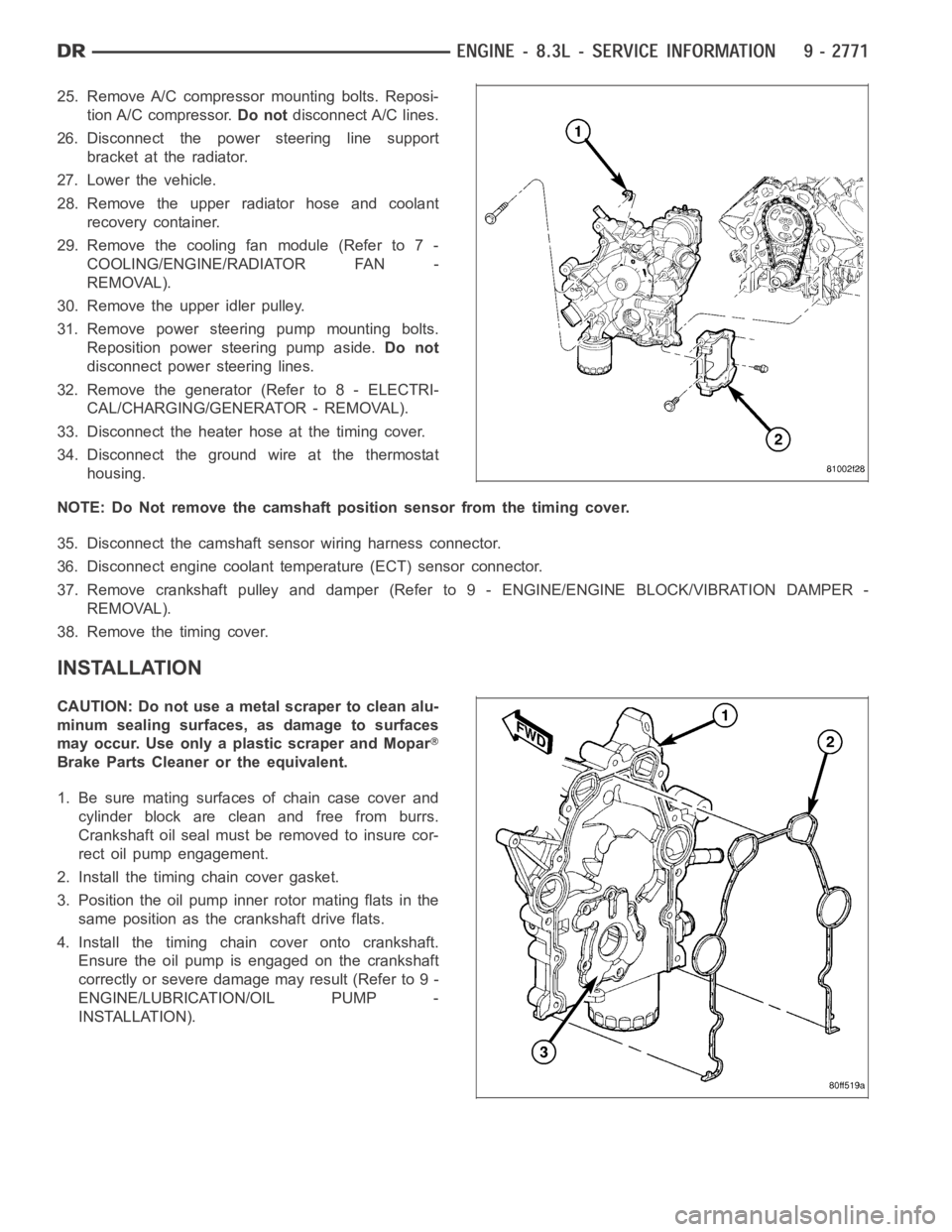
2. Install the timing chain cover gasket.
3. Position the oil pump inner rotor mating flats in the
same position as the crankshaft drive flats.
4. Install the timing chain cover onto crankshaft.
Ensure the oil pump is engaged on the crankshaft
correctly or severe damage may result (Refer to 9 -
ENGINE/LUBRICATION/OIL PUMP -
INSTALLATION).