2006 DODGE RAM SRT-10 charging
[x] Cancel search: chargingPage 2735 of 5267
When Monitored:
With the engine running and the PCM has closed the Transmission Control Relay.
Set Condition:
If the battery voltage of the Transmission Control Relay Output Sense circuit(s) to the PCM is less than 10.0
volts for the period of 15 seconds. Note: P0562 generally indicates a gradually falling battery voltage or a
resistive connection(s) to the PCM. The DTC will also set if the battery voltage sensed at the PCM is less than
6.5 volts for 200ms or when Transmission Control Relay Output circuits areless than 7.2 volts for 200ms.
Possible Causes
RELATED CHARGING SYSTEM DTC’S
(Z908) OR (Z977) GROUND CIRCUIT OPEN OR HIGH RESISTANCE
(A104) FUSED B(+) CIRCUIT OPEN OR HIGH RESISTANCE
(T16) TRANSMISSION CONTROL OUTPUT TO TCM OPEN OR HIGH RESISTANCE
TOTALLY INTEGRATED POWER MODULE (TIPM)
POWERTRAIN CONTROL MODULE
Always perform the Pre-Diagnostic Troubleshooting procedure before proceeding. (Refer to 21 - TRANSMIS-
SION/TRANSAXLE/AUTOMATIC - 42RLE - STANDARD PROCEDURE)
Theory of Operation
Transmission damage may occur if there is insufficient supply voltage to properly control the solenoids. To prevent
this possibility, the battery voltage is monitored and the system is placed in logical limp-in if the battery voltage
drops below the limit.
Diagnostic Test
1.CHECK FOR RELATED CHARGING SYSTEM DTC’S
With the scan tool, read the Engine DTC’s.
Are there any Charging System related DTCs present?
Ye s>>
Refer to the Charging System category and repair any Charging System DTCs before proceeding. After
repairing the Charging System DTCs, perform the Transmission Verification test to verify the transmis-
sion and or controller was not damaged.
Perform 42RLE TRANSMISSION VERIFICATION TEST - VER 1. (Refer to 21 - TRANSMISSION/
TRANSAXLE/AUTOMATIC - 42RLE - STANDARD PROCEDURE)
No>>
Go To 2
2.CHECK FOR TIPM DTCS
NOTE: Generator, battery, and charging system must be fully functional before performing this test.
With the scan tool, read TIPM DTCs.
Are there any TIPM TCM Power Control Circuit DTCs present also?
Ye s>>
Refer to the Transmission category and perform the appropriate symptom.
No>>
Go To 3
Page 3111 of 5267
When Monitored:
With the engine running and the PCM has closed the Transmission Control Relay.
Set Condition:
If the battery voltage of the Transmission Output circuit(s) to the PCM is less than 10.0 volts for the period of
15 seconds. Note: P0562 generally indicates a gradually falling battery voltage or a resistive connection(s) to
the PCM. The DTC will also set if the battery voltage sensed at the PCM is lessthan 6.5-volts for 200ms or
where the Transmission Output circuits are less than 7.2-volts for 200ms.
Possible Causes
RELATED CHARGING SYSTEM DTC’S
(Z904, Z908, Z977) GROUND CIRCUITS OPEN OR HIGH RESISTANCE
(T16) TIPM OUTPUT CIRCUIT OPEN OR HIGH RESISTANCE
TOTALLY INTEGRATED POWER MODULE (TIPM)
POWERTRAIN CONTROL MODULE
Always perform the 45RFE/545RFE Pre-Diagnostic Troubleshooting Procedure before proceeding. (Refer to
21 - TRANSMISSION/TRANSAXLE/AUTOMATIC - 45RFE/545RFE - STANDARD PROCEDURE)
Theory of Operation
Friction element distress could result from an insufficient supply voltage to properly control the solenoids. To prevent
this possibility, the battery voltage is monitored and the system is placed in logical limp-in if the battery voltage
drops below the limit.
Diagnostic Test
1.RELATED CHARGING SYSTEM DTCS
With the scan tool, read the Engine DTCs.
Are there any related Charging System DTCs also present?
Ye s>>
Refer to the Charging System category and repair any Engine Charging System DTCs, before testing
DTC P0562. NOTE: After repairing the Engine Charging System DTC’s, perform the Transmission Ver-
ification test to verify the transmission control systemwas not damaged.
Perform 45RFE/545RFE TRANSMISSION VERIFICATION TEST - VER 1. (Refer to 21- TRANSMIS-
SION/TRANSAXLE/AUTOMATIC - 45RFE/545RFE - STANDARD PROCEDURE)
No>>
Go To 2
2.CHECK FOR TIPM DTCS
NOTE: Generator, battery, and charging system must be fully functional before performing this test.
With the scan tool, read TIPM DTCs.
Are there any TCM TIPM DTCs present.
Ye s>>
Refer to the Transmission category and perform the appropriate symptom. (Refer to 21 - TRANSMIS-
SION/TRANSAXLE/AUTOMATIC - 45RFE/545RFE - DIAGNOSIS AND TESTING)
No>>
Go To 3
Page 4658 of 5267
WINCH
DESCRIPTION
The winch uses the electrical power from the vehicle charging system to power a motor that winds wire rope into
the winch drum by means of planetary gear reduction.
The winch assembly includes the following:
Motor:The winch motor is powered by the vehicle electrical system and features a thermal protection switch
that automatically stops the motor function in the power-in direction if the motor gets too hot.
Winch Drum:The winch drum allows the wire rope to be stored on the winch and transmits forcetothewire
rope.
Wire Rope:The wire rope allows the winch to be connected to an anchor to provide a pulling force.
Fairlead:The fairlead consists of four rollers and acts as guide for the wire rope andminimizes damage to the
rope.
Automatic Brake:The winch is equipped with an automatic brake that will stop rotation of thewinch drum if
the winch motor is stopped.
Clutch Lever:The clutch lever allows the winch drum to be disconnected from the winch motor to allow the
wire rope to be pulled from the winch by hand.
Remote Socket:The remote socket allows the remote control to be attached to the control pack to allow the
winchtofunction.
Remote Control:The remote control provides the interface between the winch operator and the winch. The
remote control provides the ability to power the winch in, out, and stop thewinch.
OPERATION
Winch:The winch uses the electrical power from the vehicle charging system to power a motor that winds wire rope
into the winch drum via planetary gear reduction. By nature, a winch is capable of generating very high forces and
should be used with care. Do not operate the winch without reading and understanding the complete winch owner’s
manual.
Low Voltage Interrupt:The winch is equipped with a device that will interrupt winch function if the vehicle charging
system voltage drops to a low level. The winch will not power-in or out for 30seconds if this device is tripped. If the
interrupt is tripped, the vehicle should be operated at high idle for a few minutes to allow the vehicle charging sys-
tem to recover before continuing to winch.
Winch Motor Thermal Protection:The winch is equipped with athermalprotectiondeviceinthemotor.Ifthe
winch is operated for an excessive duration, the device may interrupt motor function to protect the winch motor.
During this time the winch will power-out but will not power-in. Allow the winch motor to cool for a few minutes
before continuing operation of the winch. The winch will resume normal function once the motor cools.
Remote Control:Tooperatethewinch,thetoggleswitchispresseddowntopowerthewinchinand up to power
the winch out. The winch will stop if the switch is left in the neutral (center) position.
Clutch Lever:The clutch lever is used to allow free spooling of the winch drum. Rotate theclutch lever on the
winch to disengage the clutch.
WARNING
WARNING: Disconnect and isolate battery negative cable before attempting any troubleshooting or repairs.
Do not disengage the clutch if the winch is under a load or wire rope is under tension.
Do not route electrical cables across sharp edges.
Do not route electrical cables through or near moving parts.
Always wear heavy leather gloves when handling a wire rope.
Never let wire rope slip through your hands.
Always keep hands clear of wire rope, hook loop, hook and fairlead opening during installation, opera-
tion, and when spooling in or out.
Always use supplied hook strap whenever spooling wire rope in or out, during installation or operation.
Failure to follow these instructions may result in personal injury.
Page 4687 of 5267
RELAY PACK
DESCRIPTION
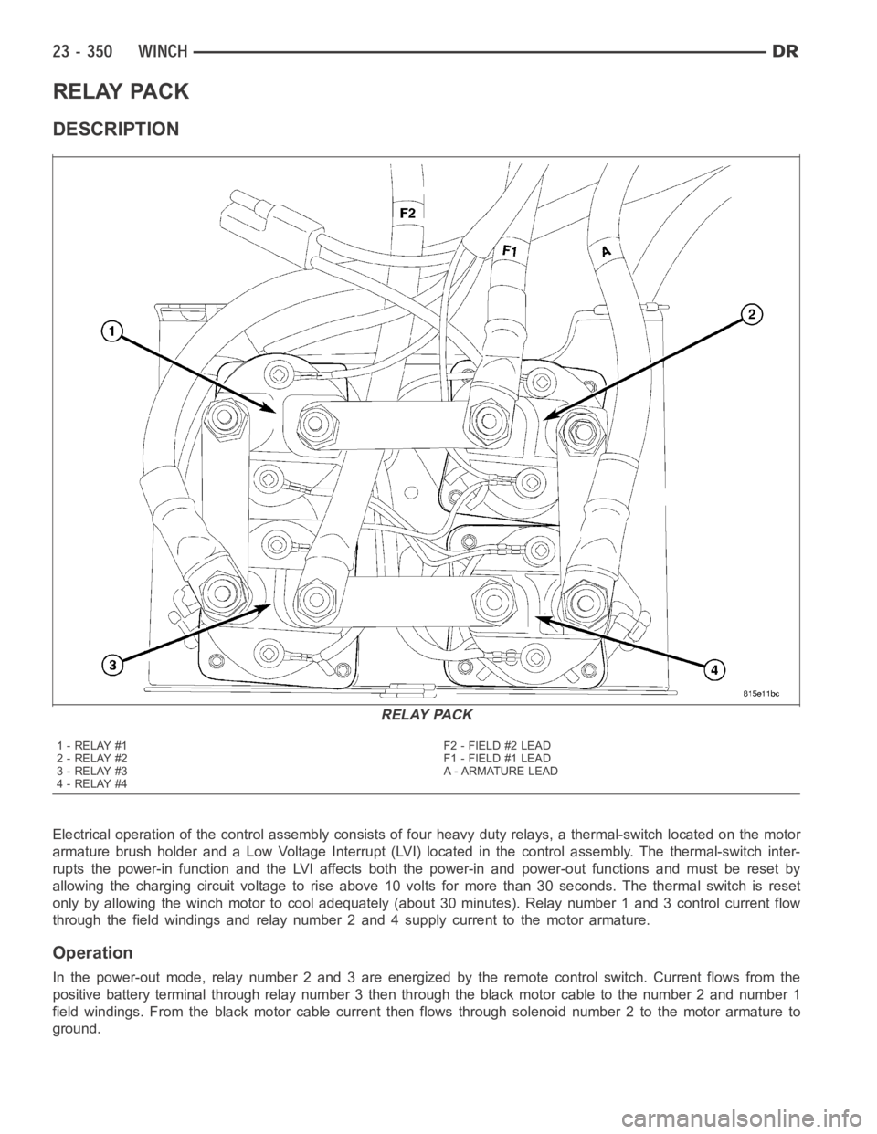
Electrical operation of the control assembly consists of four heavy duty relays, a thermal-switch located on the motor
armature brush holder and a Low Voltage Interrupt (LVI) located in the control assembly. The thermal-switch inter-
rupts the power-in function and the LVI affects both the power-in and power-out functions and must be reset by
allowing the charging circuit voltage to rise above 10 volts for more than 30 seconds. The thermal switch is reset
only by allowing the winch motor to cool adequately (about 30 minutes). Relay number 1 and 3 control current flow
through the field windings and relay number 2 and 4 supply current to the motor armature.
Operation
In the power-out mode, relay number 2 and 3 are energized by the remote control switch. Current flows from the
positive battery terminal through relay number 3 then through the black motor cable to the number 2 and number 1
field windings. From the black motor cable current then flows through solenoid number 2 to the motor armature to
ground.
RELAY PACK
1-RELAY#1
2-RELAY#2
3-RELAY#3
4-RELAY#4F2 - FIELD #2 LEAD
F1 - FIELD #1 LEAD
A - ARMATURE LEAD
Page 5054 of 5267
NOTE: When connecting the service equipment coupling to the line fitting,verify that the valve of the cou-
pling is fully closed. This will reduce the amount of effort required to make the connection.
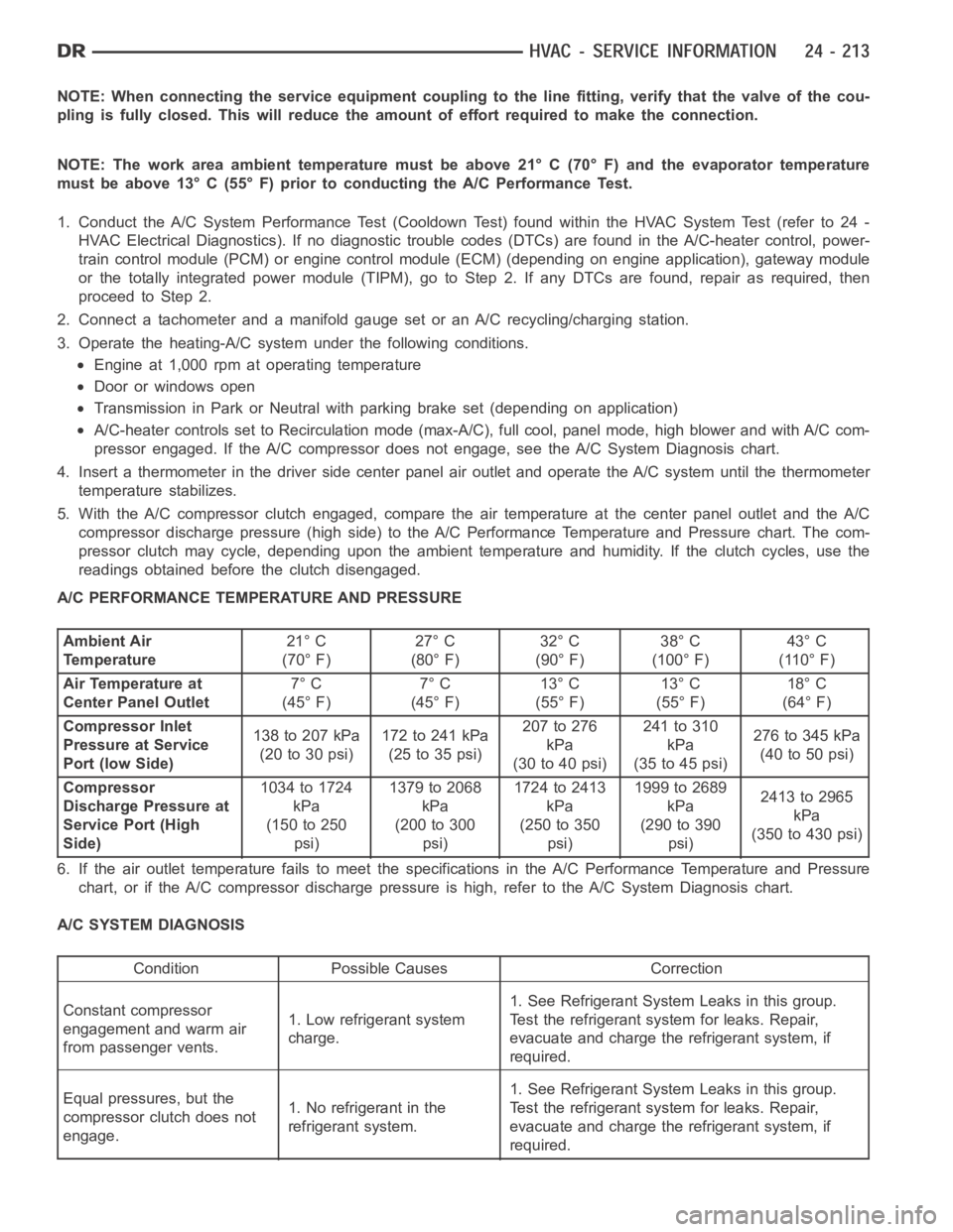
NOTE: The work area ambient temperature must be above 21° C (70° F) and the evaporator temperature
must be above 13° C (55° F) prior to conducting the A/C Performance Test.
1. Conduct the A/C System Performance Test (Cooldown Test) found within the HVAC System Test (refer to 24 -
HVAC Electrical Diagnostics). If no diagnostic trouble codes (DTCs) are found in the A/C-heater control, power-
train control module (PCM) or engine control module (ECM) (depending on engine application), gateway module
or the totally integrated power module (TIPM), go to Step 2. If any DTCs are found, repair as required, then
proceedtoStep2.
2. Connect a tachometer and a manifold gauge set or an A/C recycling/charging station.
3. Operate the heating-A/C system under the following conditions.
Engine at 1,000 rpm at operating temperature
Door or windows open
Transmission in Park or Neutral with parking brake set (depending on application)
A/C-heater controls set to Recirculation mode (max-A/C), full cool, panel mode, high blower and with A/C com-
pressor engaged. If the A/C compressor does not engage, see the A/C System Diagnosis chart.
4. Insert a thermometer in the driver side center panel air outlet and operate the A/C system until the thermometer
temperature stabilizes.
5. With the A/C compressor clutch engaged, compare the air temperature at the center panel outlet and the A/C
compressor discharge pressure (high side) to the A/C Performance Temperature and Pressure chart. The com-
pressor clutch may cycle, depending upon the ambient temperature and humidity. If the clutch cycles, use the
readings obtained before the clutch disengaged.
A/C PERFORMANCE TEMPERATURE AND PRESSURE
Ambient Air
Temperature21° C
(70° F)27° C
(80° F)32° C
(90° F)38° C
(100° F)43° C
(110° F)
Air Temperature at
Center Panel Outlet7° C
(45° F)7° C
(45° F)13° C
(55° F)13° C
(55° F)18° C
(64° F)
Compressor Inlet
Pressure at Service
Port (low Side)138 to 207 kPa
(20to30psi)172to241kPa
(25to35psi)207 to 276
kPa
(30to40psi)241 to 310
kPa
(35to45psi)276to345kPa
(40to50psi)
Compressor
Discharge Pressure at
Service Port (High
Side)1034 to 1724
kPa
(150 to 250
psi)1379to2068
kPa
(200 to 300
psi)1724to2413
kPa
(250 to 350
psi)1999 to 2689
kPa
(290 to 390
psi)2413to2965
kPa
(350 to 430 psi)
6. If the air outlet temperature fails to meet the specifications in the A/CPerformance Temperature and Pressure
chart, or if the A/C compressor discharge pressure is high, refer to the A/CSystem Diagnosis chart.
A/C SYSTEM DIAGNOSIS
Condition Possible Causes Correction
Constant compressor
engagement and warm air
from passenger vents.1. Low refrigerant system
charge.1. See Refrigerant System Leaks in this group.
Test the refrigerant system for leaks. Repair,
evacuate and charge the refrigerant system, if
required.
Equal pressures, but the
compressor clutch does not
engage.1. No refrigerant in the
refrigerant system.1. See Refrigerant System Leaks in this group.
Test the refrigerant system for leaks. Repair,
evacuate and charge the refrigerant system, if
required.
Page 5128 of 5267
WARNING: The engine cooling system is designed to develop internal pressures up to 145 kilopascals (21
pounds per square inch). Do not remove or loosen the coolant pressure cap, cylinder block drain plugs,
radiator drain, radiator hoses, heater hoses, or hose clamps while the engine cooling system is hot and
under pressure. Allow the vehicle to cool for a minimum of 15 minutes beforeopening the cooling system
for service. Failure to observe this warning can result in serious burns from the heated engine coolant.
CAUTION
CAUTION: Never add R-12 to a refrigerant system designed to use R-134a. Do not use R-12 equipment or
parts on an R-134a A/C system. These refrigerants are not compatible and damage to the A/C system will
result.
CAUTION: Never use R-12 refrigerant oil in a A/C system designed to use R-134a refrigerant oil. These
refrigerant oils are not compatible and damage to the A/C system will result.
CAUTION: The use of A/C system sealers may result in damage to A/C refrigerant recovery/evacuation/re-
charging equipment and/or A/C system. Many federal, state/provincial and local regulations prohibit the
recharge of A/C systems with known leaks. DaimlerChrysler recommends thedetection of A/C system leaks
through the use of approved leak detectors and fluorescent leak detectiondyes. Vehicles found with A/C
system sealers should be treated as contaminated and replacement of the entire A/C refrigerant system is
recommended. A/C systems found to be contaminated with A/C system sealers, A/C stop-leak products or
seal conditioners voids the warranty for the A/C system.
CAUTION: Recover the refrigerant before opening any fitting or connection. Open the fittings with caution,
even after the system has been discharged. Never open or loosen a connection before recovering the refrig-
erant.
CAUTION: If equipped, do not remove the secondary retention clip from any spring-lock coupler connection
while the refrigerant system is under pressure. Recover the refrigerant before removing the secondary
retention clip. Open the fittings with caution, even after the system has been discharged. Never open or
loosen a connection before recovering the refrigerant.
CAUTION: The internal parts of the A/C system will remain stable as long as moisture-free refrigerant and
refrigerant oil is used. Abnormal amounts of dirt, moisture or air can upset the chemical stability. This may
cause operational troubles or even serious damage if present in more than very small quantities. Before
disconnecting a component, clean the outside of the fittings thoroughly to prevent contamination from
entering the refrigerant system. Keep service tools and the work area clean. Do not open the refrigerant
system or uncap a replacement component until you are ready to service the system. Immediately after
disconnecting a component from the refrigerant system, seal the open fittings with a cap or plug. This will
prevent contamination from entering the A/C system.
CAUTION: Refrigerant oil will absorb moisture from the atmosphere if leftuncapped. Do not open a con-
tainer of refrigerant oil until you are ready to use it. Replace the cap on the oil container immediately after
using. Store refrigerant oil only in a clean, airtight, and moisture-freecontainer.
CAUTION: Do not overcharge the refrigerant system. Overcharging will cause excessive compressor head
pressure and can cause compressor noise and A/C system failure.
Page 5130 of 5267
STANDARD PROCEDURE
REFRIGERANT SYSTEM SERVICE EQUIPMENT
WARNING: Eye protection must be worn when servicing an A/C refrigerant system. Turn all valves off
(rotate clockwise) on the equipment being used before connecting or disconnecting service equipment from
the refrigerant system. Failure to observe these warnings may result in personal injury or death.
WARNING: Refer to the applicable warnings and cautions for this system before performing the following
operation (Refer to 24 - HEATING & AIR CONDITIONING/PLUMBING - WARNINGS) and (Refer to 24 - HEAT-
ING & AIR CONDITIONING/PLUMBING - CAUTIONS). Failure to follow the warnings and cautions could result
in possible personal injury or death.
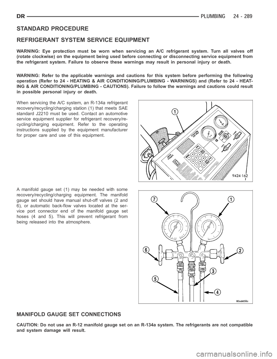
When servicing the A/C system, an R-134a refrigerant
recovery/recycling/charging station (1) that meets SAE
standard J2210 must be used. Contact an automotive
service equipment supplier for refrigerant recovery/re-
cycling/charging equipment. Refer to the operating
instructions supplied by the equipment manufacturer
for proper care and use of this equipment.
A manifold gauge set (1) may be needed with some
recovery/recycling/charging equipment. The manifold
gauge set should have manual shut-off valves (2 and
6), or automatic back-flow valves located at the ser-
vice port connector end of the manifold gauge set
hoses (4 and 5). This will prevent refrigerant from
being released into the atmosphere.
MANIFOLD GAUGE SET CONNECTIONS
CAUTION: Do not use an R-12 manifold gauge set on an R-134a system. The refrigerants are not compatible
and system damage will result.
Page 5131 of 5267
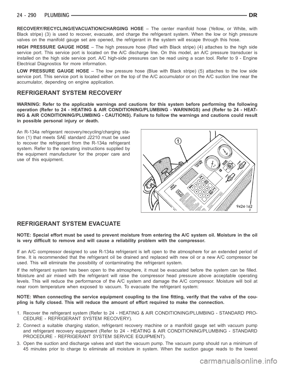
RECOVERY/RECYCLING/EVACUATION/CHARGING HOSE– The center manifold hose (Yellow, or White, with
Black stripe) (3) is used to recover, evacuate, and charge the refrigerantsystem. When the low or high pressure
valves on the manifold gauge set are opened, the refrigerant in the system will escape through this hose.
HIGH PRESSURE GAUGE HOSE– The high pressure hose (Red with Black stripe) (4) attaches to the high side
service port. This service port is located on the A/C discharge line. On this model, an A/C pressure transducer is
installed on the high side service port. A/C high-side pressures can be read using a scan tool. Refer to 9 - Engine
Electrical Diagnostics for more information.
LOW PRESSURE GAUGE HOSE– The low pressure hose (Blue with Black stripe) (5) attaches to the low side
service port. This service port is located either on the top of the A/C accumulator or on the A/C suction line near the
accumulator, depending on engine application.
REFRIGERANT SYSTEM RECOVERY
WARNING: Refer to the applicable warnings and cautions for this system before performing the following
operation (Refer to 24 - HEATING & AIR CONDITIONING/PLUMBING - WARNINGS) and (Refer to 24 - HEAT-
ING & AIR CONDITIONING/PLUMBING - CAUTIONS). Failure to follow the warnings and cautions could result
in possible personal injury or death.
An R-134a refrigerant recovery/recycling/charging sta-
tion (1) that meets SAE standard J2210 must be used
to recover the refrigerant from the R-134a refrigerant
system. Refer to the operating instructions supplied by
the equipment manufacturer for the proper care and
use of this equipment.
REFRIGERANT SYSTEM EVACUATE
NOTE: Special effort must be used to prevent moisture from entering the A/Csystem oil. Moisture in the oil
is very difficult to remove and will cause a reliability problem with the compressor.
If an A/C compressor designed to use R-134a refrigerant is left open to the atmosphere for an extended period of
time. It is recommended that the refrigerant oil be drained and replaced with new oil or a new A/C compressor be
used. This will eliminate the possibility of contaminating the refrigerant system.
If the refrigerant system has been open to the atmosphere, it must be evacuated before the system can be filled.
Moisture and air mixed with the refrigerant will raise the compressor headpressure above acceptable operating
levels. This will reduce the performance of the A/C system and damage the A/C compressor. Moisture will boil at
near room temperature when exposed to vacuum. To evacuate the refrigerantsystem:
NOTE: When connecting the service equipment coupling to the line fitting,verify that the valve of the cou-
pling is fully closed. This will reduce the amount of effort required to make the connection.
1. Recover the refrigerant system (Refer to 24 - HEATING & AIR CONDITIONING/PLUMBING - STANDARD PRO-
CEDURE - REFRIGERANT SYSTEM RECOVERY).
2. Connect a suitable charging station, refrigerant recovery machine or amanifold gauge set with vacuum pump
and refrigerant recovery equipment (Refer to 24 - HEATING & AIR CONDITIONING/PLUMBING - STANDARD
PROCEDURE - REFRIGERANT SYSTEM SERVICE EQUIPMENT).
3. Open the suction and discharge valves and start the vacuum pump. The vacuum pump should run a minimum of
45minutespriortochargetoeliminateall moisture in system. When the suction gauge reads to the lowest