2006 DODGE RAM SRT-10 fuel pump
[x] Cancel search: fuel pumpPage 88 of 5267
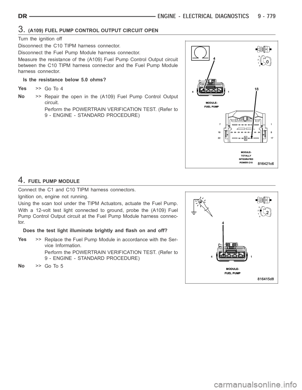
3.(A109) FUEL PUMP CONTROL OUTPUT CIRCUIT OPEN
Turn the ignition off
Disconnect the C10 TIPM harness connector.
Disconnect the Fuel Pump Module harness connector.
Measure the resistance of the (A109) Fuel Pump Control Output circuit
between the C10 TIPM harness connector and the Fuel Pump Module
harness connector.
Is the resistance below 5.0 ohms?
Ye s>>
Go To 4
No>>
Repair the open in the (A109) Fuel Pump Control Output
circuit.
Perform the POWERTRAIN VERIFICATION TEST. (Refer to
9 - ENGINE - STANDARD PROCEDURE)
4.FUEL PUMP MODULE
Connect the C1 and C10 TIPM harness connectors.
Ignition on, engine not running.
Using the scan tool under the TIPM Actuators, actuate the Fuel Pump.
With a 12-volt test light connected to ground, probe the (A109) Fuel
Pump Control Output circuit at the Fuel Pump Module harness connec-
tor.
Does the test light illuminate brightly and flash on and off?
Ye s>>
Replace the Fuel Pump Module in accordance with the Ser-
vice Information.
Perform the POWERTRAIN VERIFICATION TEST. (Refer to
9 - ENGINE - STANDARD PROCEDURE)
No>>
Go To 5
Page 90 of 5267
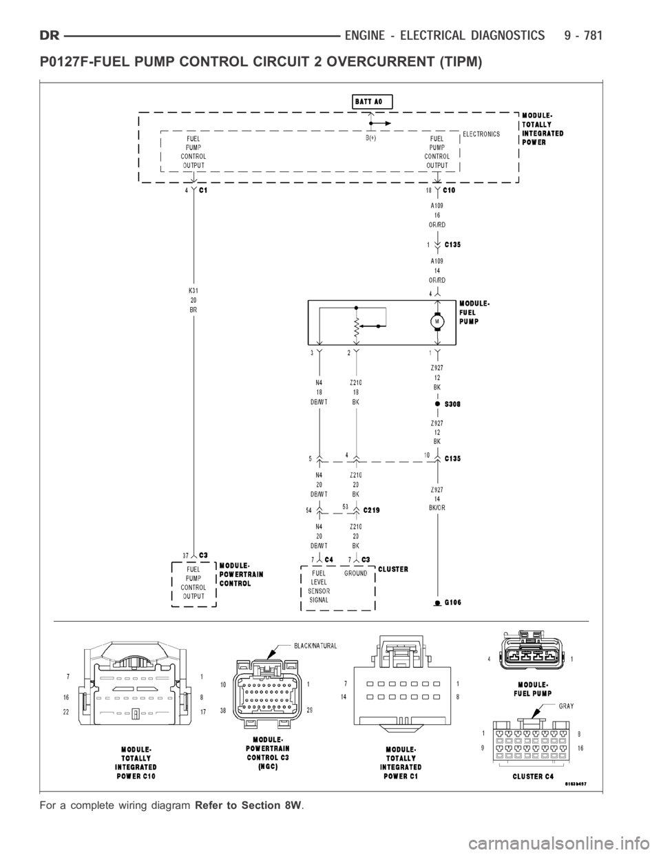
P0127F-FUEL PUMP CONTROL CIRCUIT 2 OVERCURRENT (TIPM)
For a complete wiring diagramRefer to Section 8W.
Page 91 of 5267
When Monitored:
With the ignition on. Battery voltage greater than 10.4 volts. TIPM requesting Fuel Pump operation.
Set Condition:
An overcurrent condition is detected in the fuel pump control output circuit. One Trip Fault. Three good trips to
turn off the MIL.
Possible Causes
TERMINAL DAMAGE OR CORROSION
FUEL PUMP MOTOR GROUND HIGH RESISTANCE
(A109) FUEL PUMP CONTROL OUTPUT CIRCUIT HIGH RESISTANCE
FUEL PUMP MOTOR
TIPM
Always perform the Pre-Diagnostic Troubleshooting procedure before proceeding. (Refer to 9 - ENGINE -
DIAGNOSIS AND TESTING).
Diagnostic Test
1.FUEL PUMP OPERATION
Ignition on, engine not running.
With a scan tool in the TIPM Actuators, actuate the Fuel Pump.
Is the Fuel Pump operating?
Ye s>>
Refer to the INTERMITTENT CONDITION Diagnostic Procedure.
Perform the POWERTRAIN VERIFICATION TEST. (Refer to 9 - ENGINE - STANDARD PROCEDURE)
No>>
Go To 2
2.VISUAL AND PHYSICAL CONNECTOR AND TERMINAL INSPECTION
Turn the ignition off.
Disconnect the C10 TIPM harness connector.
Disconnect the Fuel Pump Module harness connector.
Inspect the terminal and connector condition. Check for signs of corrosion build up or damage the would compro-
mise the terminal to controller pin connector.
NOTE: Make sure that all in-line connectors are inspected for corrosion and/or damage.
Visually inspect the wiring harness. Look for any chafed, pierced, pinched or partially broken wires hidden in the
wire insulation.
Were any of the above conditions found?
Ye s>>
Repair or replace as necessary.
Perform the POWERTRAIN VERIFICATION TEST. (Refer to 9 - ENGINE - STANDARD PROCEDURE)
No>>
Go To 3
Page 92 of 5267
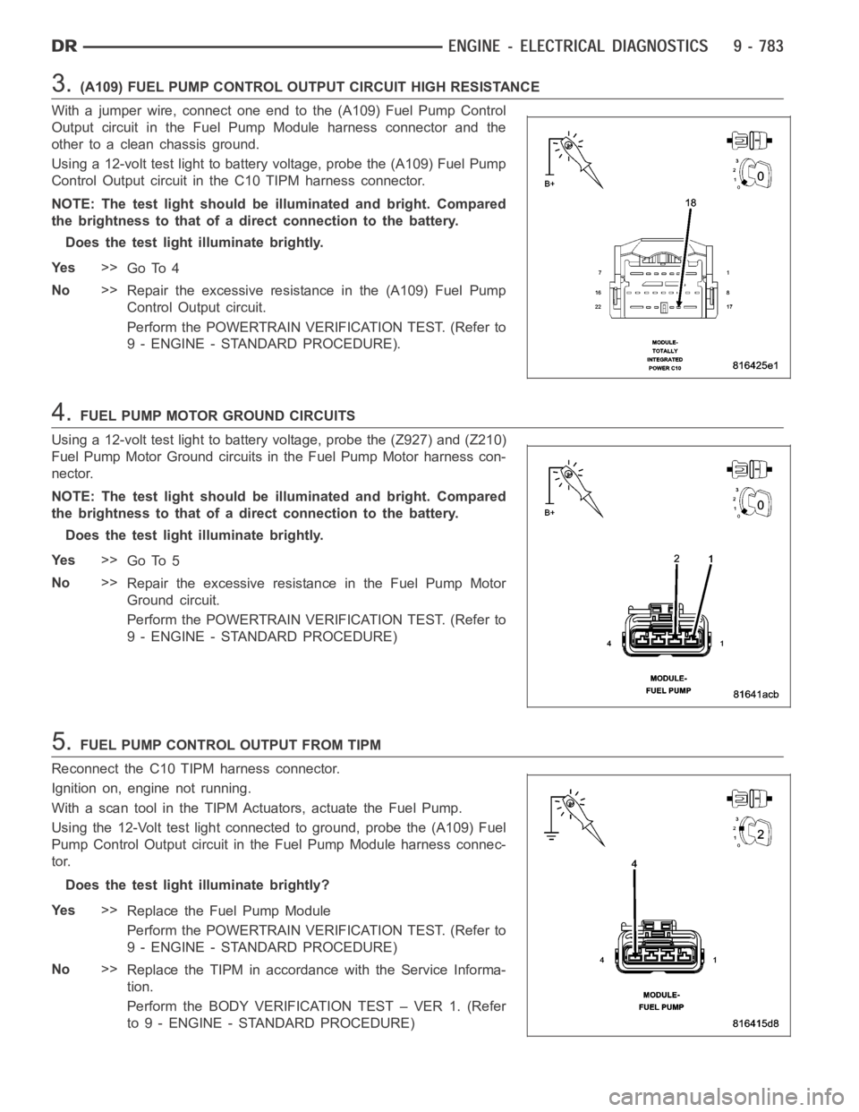
3.(A109) FUEL PUMP CONTROL OUTPUT CIRCUIT HIGH RESISTANCE
With a jumper wire, connect one end to the (A109) Fuel Pump Control
Output circuit in the Fuel Pump Module harness connector and the
other to a clean chassis ground.
Using a 12-volt test light to battery voltage, probe the (A109) Fuel Pump
Control Output circuit in the C10 TIPM harness connector.
NOTE: The test light should be illuminated and bright. Compared
the brightness to that of a direct connection to the battery.
Does the test light illuminate brightly.
Ye s>>
Go To 4
No>>
Repair the excessive resistance in the (A109) Fuel Pump
Control Output circuit.
Perform the POWERTRAIN VERIFICATION TEST. (Refer to
9 - ENGINE - STANDARD PROCEDURE).
4.FUEL PUMP MOTOR GROUND CIRCUITS
Using a 12-volt test light to battery voltage, probe the (Z927) and (Z210)
Fuel Pump Motor Ground circuits in the Fuel Pump Motor harness con-
nector.
NOTE: The test light should be illuminated and bright. Compared
the brightness to that of a direct connection to the battery.
Does the test light illuminate brightly.
Ye s>>
Go To 5
No>>
Repair the excessive resistance in the Fuel Pump Motor
Ground circuit.
Perform the POWERTRAIN VERIFICATION TEST. (Refer to
9 - ENGINE - STANDARD PROCEDURE)
5.FUEL PUMP CONTROL OUTPUT FROM TIPM
Reconnect the C10 TIPM harness connector.
Ignition on, engine not running.
With a scan tool in the TIPM Actuators, actuate the Fuel Pump.
Using the 12-Volt test light connected to ground, probe the (A109) Fuel
Pump Control Output circuit in the Fuel Pump Module harness connec-
tor.
Does the test light illuminate brightly?
Ye s>>
Replace the Fuel Pump Module
Perform the POWERTRAIN VERIFICATION TEST. (Refer to
9 - ENGINE - STANDARD PROCEDURE)
No>>
Replace the TIPM in accordance with the Service Informa-
tion.
Perform the BODY VERIFICATION TEST – VER 1. (Refer
to 9 - ENGINE - STANDARD PROCEDURE)
Page 427 of 5267

Possible Causes
RESTRICTED FUEL SUPPLY LINE
FUEL PUMP INLET STRAINER PLUGGED
(A109) FUEL PUMP RELAY OUTPUT CIRCUIT OPEN
FUEL PUMP RELAY
FUEL PUMP
Diagnostic Test
1.FUEL PUMP OPERATION
Ignition on, engine not running.
With a scan tool, actuate the Fuel System test.
NOTE: It may be necessary to use a mechanics stethoscope in the next step.
Listen for fuel pump operation at the fuel tank.
Does the Fuel Pump operate?
Ye s>>
Go To 2
No>>
Go To 5
CAUTION: Stop All Actuations.
2.FUEL PRESSURE
Turn the ignition off.
WARNING: The fuel system is under a constant pressure (even with the engineoff). Before testing or ser-
vicing any fuel system hose, fitting or line, the fuel system pressure mustbe released. Failure to follow
these instructions can result in personal injury or death.
Install a fuel pressure gauge at the engine.
Ignition on, engine not running.
With the scan tool, actuate the ASD FuelSystem test and observe the fuel pressure gauge.
NOTE: NOTE: Fuel pressure specification is 407 KPa +/- 34 KPa (59 psi +/- 5 psi).
Choose a conclusion that best matches your fuel pressure reading.
Below Specification
Go To 3
Within Specification
Te s t C o m p l e t e .
Above Specification
Replace the fuel filter/fuel pressure regulator.
Perform the POWERTRAIN VERIFICATION TEST. (Refer to 9 - ENGINE - STANDARD PROCEDURE)
CAUTION: Stop All Actuations.
3.RESTRICTED FUEL SUPPLY LINE
Turn the ignition off.
WARNING: The fuel system is under a constant pressure even with the engine off. Before testing or ser-
vicing any fuel system hose, fitting or line, the fuel system pressure mustbe released.
Raise vehicle on hoist, and disconnect the fuel pressure line at the fuel pump module.
Install special tool #6539 (5/16
) or #6631(3/8) fuel line adapter and the fuel pressure gauge between the fuel sup-
ply line and the fuel pump module.
Ignition on, engine not running.
With the scan tool, actuate the ASD FuelSystem test and observe the fuel pressure gauge.
Page 428 of 5267

NOTE: Fuel pressure specification is 407 KPa +/- 34 KPa (59 psi +/- 5 psi).
CAUTION: Stop All Actuations.
Is the fuel pressure within specification now?
Ye s>>
Repair/replace fuel supply line as necessary.
Perform the POWERTRAIN VERIFICATION TEST. (Refer to 9 - ENGINE - STANDARD PROCEDURE)
No>>
Go To 4
4.CHECKING FUEL INLET STRAINER
Turn the ignition off.
WARNING: The fuel system is under a constant pressure (even with the engineoff). Before testing or ser-
vicing any fuel system hose, fitting or line, the fuel system pressure mustbe released. Failure to follow
these instructions can result in personal injury or death.
Remove the Fuel Pump Module and inspect the Fuel Inlet Strainer.
Is the Fuel Inlet Strainer plugged?
Ye s>>
Replace the Fuel Pump Inlet Strainer.
Perform the POWERTRAIN VERIFICATION TEST. (Refer to 9 - ENGINE - STANDARD PROCEDURE)
No>>
Replace the Fuel Pump Module.
Perform the POWERTRAIN VERIFICATION TEST. (Refer to 9 - ENGINE - STANDARD PROCEDURE)
5.(A109) FUEL PUMP RELAY OUTPUT CIRCUIT OPEN
Turn the ignition off.
Remove the Fuel Pump Relay from the IPM.
Disconnect the Fuel Pump Module harness connector.
Measure the resistance of the (A109) Fuel Pump Relay Output circuit
from the relay connector to the fuel pump module connector.
Is the resistance below 5.0 ohms?
Ye s>>
Replace the Fuel Pump Relay.
Perform the POWERTRAIN VERIFICATION TEST. (Refer to
9 - ENGINE - STANDARD PROCEDURE)
No>>
Repair the open in the (A109) Fuel Pump Relay Output cir-
cuit.
Perform the POWERTRAIN VERIFICATION TEST. (Refer to
9 - ENGINE - STANDARD PROCEDURE)
Page 429 of 5267
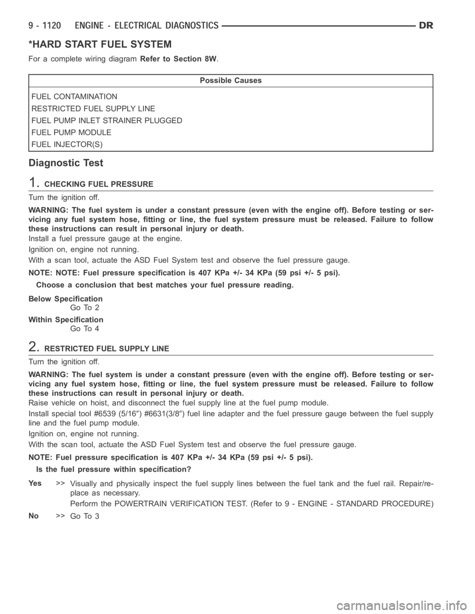
*HARD START FUEL SYSTEM
For a complete wiring diagramRefer to Section 8W.
Possible Causes
FUEL CONTAMINATION
RESTRICTED FUEL SUPPLY LINE
FUEL PUMP INLET STRAINER PLUGGED
FUEL PUMP MODULE
FUEL INJECTOR(S)
Diagnostic Test
1.CHECKING FUEL PRESSURE
Turn the ignition off.
WARNING: The fuel system is under a constant pressure (even with the engineoff). Before testing or ser-
vicing any fuel system hose, fitting or line, the fuel system pressure mustbe released. Failure to follow
these instructions can result in personal injury or death.
Install a fuel pressure gauge at the engine.
Ignition on, engine not running.
With a scan tool, actuate the ASD Fuel System test and observe the fuel pressure gauge.
NOTE: NOTE: Fuel pressure specification is 407 KPa +/- 34 KPa (59 psi +/- 5 psi).
Choose a conclusion that best matches your fuel pressure reading.
Below Specification
Go To 2
Within Specification
Go To 4
2.RESTRICTED FUEL SUPPLY LINE
Turn the ignition off.
WARNING: The fuel system is under a constant pressure (even with the engineoff). Before testing or ser-
vicing any fuel system hose, fitting or line, the fuel system pressure mustbe released. Failure to follow
these instructions can result in personal injury or death.
Raise vehicle on hoist, and disconnect the fuel supply line at the fuel pumpmodule.
Install special tool #6539 (5/16
) #6631(3/8) fuel line adapter and the fuel pressure gauge between the fuel supply
line and the fuel pump module.
Ignition on, engine not running.
With the scan tool, actuate the ASD FuelSystem test and observe the fuel pressure gauge.
NOTE: Fuel pressure specification is 407 KPa +/- 34 KPa (59 psi +/- 5 psi).
Is the fuel pressure within specification?
Ye s>>
Visually and physically inspect the fuel supply lines between the fuel tank and the fuel rail. Repair/re-
place as necessary.
Perform the POWERTRAIN VERIFICATION TEST. (Refer to 9 - ENGINE - STANDARD PROCEDURE)
No>>
Go To 3
Page 430 of 5267
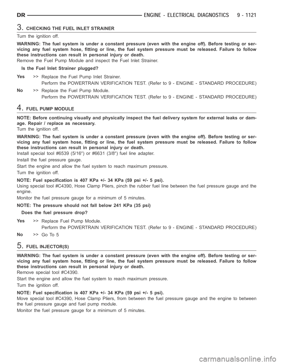
3.CHECKING THE FUEL INLET STRAINER
Turn the ignition off.
WARNING: The fuel system is under a constant pressure (even with the engineoff). Before testing or ser-
vicing any fuel system hose, fitting or line, the fuel system pressure mustbe released. Failure to follow
these instructions can result in personal injury or death.
Remove the Fuel Pump Module and inspect the Fuel Inlet Strainer.
Is the Fuel Inlet Strainer plugged?
Ye s>>
Replace the Fuel Pump Inlet Strainer.
Perform the POWERTRAIN VERIFICATION TEST. (Refer to 9 - ENGINE - STANDARD PROCEDURE)
No>>
Replace the Fuel Pump Module.
Perform the POWERTRAIN VERIFICATION TEST. (Refer to 9 - ENGINE - STANDARD PROCEDURE)
4.FUEL PUMP MODULE
NOTE: Before continuing visually and physically inspect the fuel delivery system for external leaks or dam-
age. Repair / replace as necessary.
Turn the ignition off.
WARNING: The fuel system is under a constant pressure (even with the engineoff). Before testing or ser-
vicing any fuel system hose, fitting or line, the fuel system pressure mustbe released. Failure to follow
these instructions can result in personal injury or death.
Install special tool #6539 (5/16
) or #6631 (3/8) fuel line adapter.
Install the fuel pressure gauge.
Start the engine and allow the fuel system to reach maximum pressure.
Turn the ignition off.
NOTE: Fuel specification is 407 KPa +/- 34 KPa (59 psi +/- 5 psi).
Using special tool #C4390, Hose Clamp Pliers, pinch the rubber fuel line between the fuel pressure gauge and the
engine.
Monitor the fuel pressure gauge for a minimum of 5 minutes.
NOTE: The pressure should not fall below 241 KPa (35 psi)
Does the fuel pressure drop?
Ye s>>
Replace Fuel Pump Module.
Perform the POWERTRAIN VERIFICATION TEST. (Refer to 9 - ENGINE - STANDARD PROCEDURE)
No>>
Go To 5
5.FUEL INJECTOR(S)
WARNING: The fuel system is under a constant pressure (even with the engineoff). Before testing or ser-
vicing any fuel system hose, fitting or line, the fuel system pressure mustbe released. Failure to follow
these instructions can result in personal injury or death.
Remove special tool #C4390.
Start the engine and allow the fuel system to reach maximum pressure.
Turn the ignition off.
NOTE: Fuel specification is 407 KPa +/- 34 KPa (59 psi +/- 5 psi).
Move special tool #C4390, Hose Clamp Pliers, from between the fuel pressure gauge and the engine to between
the fuel pressure gauge and fuel pump module.
Monitor the fuel pressure gauge for a minimum of 5 minutes.