2006 DODGE RAM SRT-10 catalytic converter
[x] Cancel search: catalytic converterPage 1263 of 5267
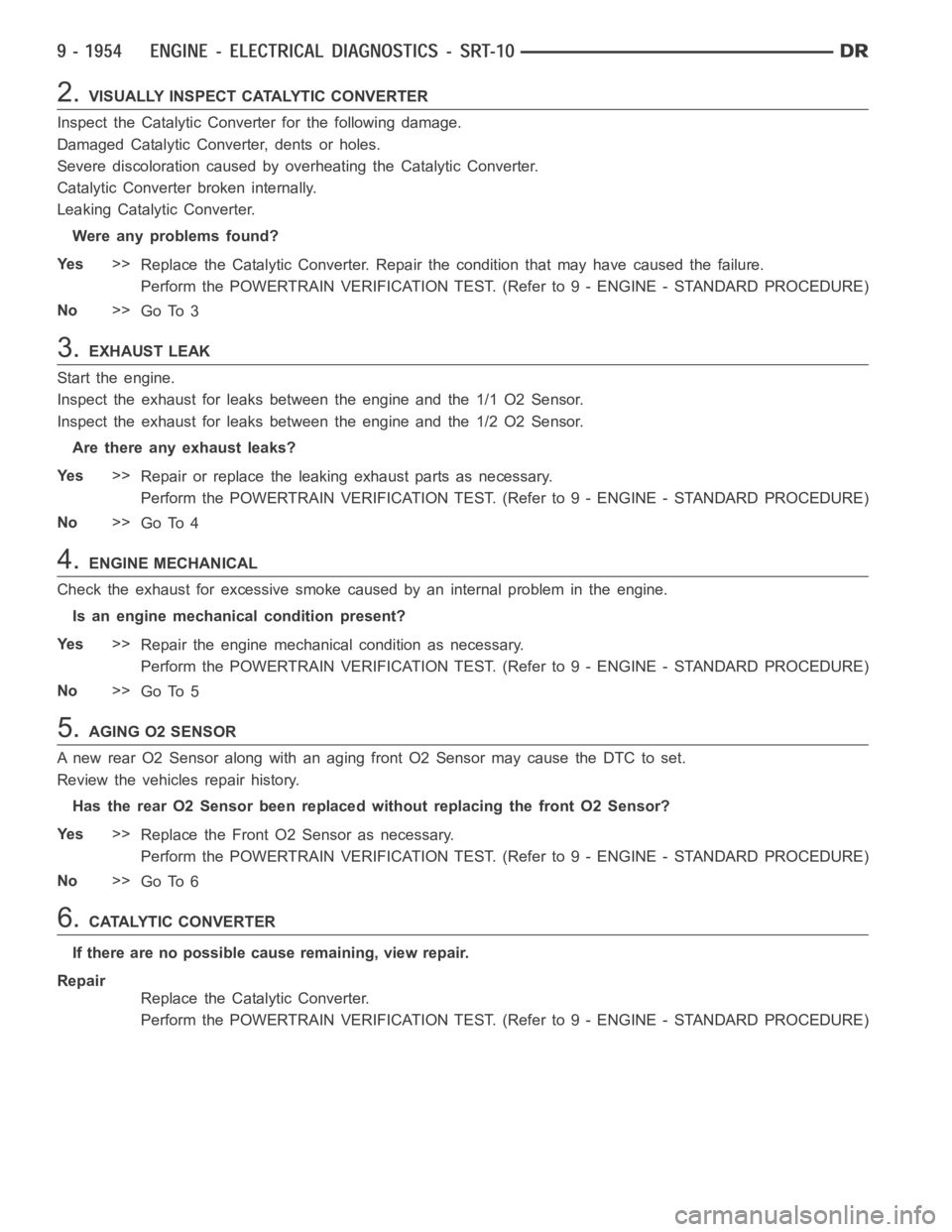
2.VISUALLY INSPECT CATALYTIC CONVERTER
Inspect the Catalytic Converter for the following damage.
Damaged Catalytic Converter, dents or holes.
Severe discoloration caused by overheating the Catalytic Converter.
Catalytic Converter broken internally.
Leaking Catalytic Converter.
Were any problems found?
Ye s>>
Replace the Catalytic Converter. Repair the condition that may have caused the failure.
Perform the POWERTRAIN VERIFICATION TEST. (Refer to 9 - ENGINE - STANDARD PROCEDURE)
No>>
Go To 3
3.EXHAUST LEAK
Start the engine.
Inspect the exhaust for leaks between the engine and the 1/1 O2 Sensor.
Inspect the exhaust for leaks between the engine and the 1/2 O2 Sensor.
Are there any exhaust leaks?
Ye s>>
Repair or replace the leaking exhaust parts as necessary.
Perform the POWERTRAIN VERIFICATION TEST. (Refer to 9 - ENGINE - STANDARD PROCEDURE)
No>>
Go To 4
4.ENGINE MECHANICAL
Check the exhaust for excessive smoke caused by an internal problem in the engine.
Is an engine mechanical condition present?
Ye s>>
Repair the engine mechanical condition as necessary.
Perform the POWERTRAIN VERIFICATION TEST. (Refer to 9 - ENGINE - STANDARD PROCEDURE)
No>>
Go To 5
5.AGING O2 SENSOR
A new rear O2 Sensor along with an aging front O2 Sensor may cause the DTC to set.
Review the vehicles repair history.
Has the rear O2 Sensor been replaced without replacing the front O2 Sensor?
Ye s>>
Replace the Front O2 Sensor as necessary.
Perform the POWERTRAIN VERIFICATION TEST. (Refer to 9 - ENGINE - STANDARD PROCEDURE)
No>>
Go To 6
6.CATALYTIC CONVERTER
If there are no possible cause remaining, view repair.
Repair
Replace the Catalytic Converter.
Perform the POWERTRAIN VERIFICATION TEST. (Refer to 9 - ENGINE - STANDARD PROCEDURE)
Page 1264 of 5267
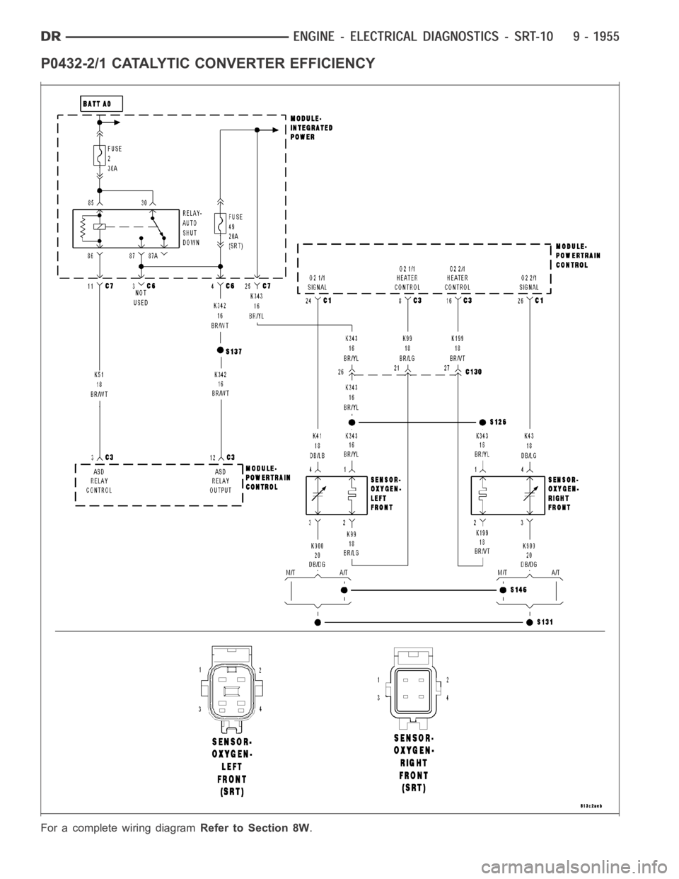
P0432-2/1 CATALYTIC CONVERTER EFFICIENCY
For a complete wiring diagramRefer to Section 8W.
Page 1265 of 5267

Theory of Operation
The upstream O2 sensor is used to detect the amount of oxygen in the exhaust gas before the gas enters the
catalytic converter. During the catalyst/O2 monitor test, the response rate (cycles/second) of the upstream O2 sen-
sor determines the sensor’s ability to achieve the tailpipe emissions limits. The response rate of the downstream O2
sensor relative to the upstream O2 sensor response rate measures the catalyst’s ability to store oxygen and is used
to infer the catalyst’s ability to achieve the tailpipe emissions limits.
When Monitored:
After engine warm up to 147 deg. F, 180 seconds of open throttle operation, at a speed greater than 20 mph,
with the engine at 1200-1700 rpm and MAP vacuum between 15.0 and 21.0 inchesof mercury (Hg).
Set Condition:
As catalyst efficiency deteriorates, the switch rate of the downstream O2sensor approaches that of the
upstream O2 sensor. If at any point during the test the switch ratio reachesa predetermined value a counter
is incremented by one. Three good trips to turn off the MIL.
Possible Causes
EXHAUST LEAK
ENGINE MECHANICAL
AGING O2 SENSOR
CATALYTIC CONVERTER
Always perform the Pre-Diagnostic Troubleshooting procedure before proceeding. (Refer to 9 - ENGINE -
DIAGNOSIS AND TESTING).
Diagnostic Test
1.ACTIVE DTC
NOTE: A new rear O2 Sensor along with an aging front O2 Sensor may cause the DTCtoset.Reviewthe
repair history of the vehicle before continuing.
NOTE: If an O2 Sensor DTC set along with the Catalytic Converter EfficiencyDTC diagnose the O2 Sensor
DTC(s) before continuing.
NOTE: Check for contaminants that may have damaged the O2 Sensor and Catalytic Converter: contami-
nated fuel, unapproved silicone, oil and coolant, repair necessary.
Ignition on, engine not running.
With a scan tool, read DTCs.
Is the DTC active at this time?
Ye s>>
Go To 2
No>>
Refer to the INTERMITTENT CONDITION Diagnostic Procedure.
Perform the POWERTRAIN VERIFICATION TEST. (Refer to 9 - ENGINE - STANDARD PROCEDURE)
2.VISUALLY INSPECT CATALYTIC CONVERTER
Inspect the Catalytic Converter for the following damage.
Damaged Catalytic Converter, dents or holes.
Severe discoloration caused by overheating the Catalytic Converter.
Catalytic Converter broken internally.
Leaking Catalytic Converter.
Were any problems found?
Ye s>>
Replace the Catalytic Converter. Repair the condition that may have caused the failure.
Perform the POWERTRAIN VERIFICATION TEST. (Refer to 9 - ENGINE - STANDARD PROCEDURE)
No>>
Go To 3
Page 1266 of 5267
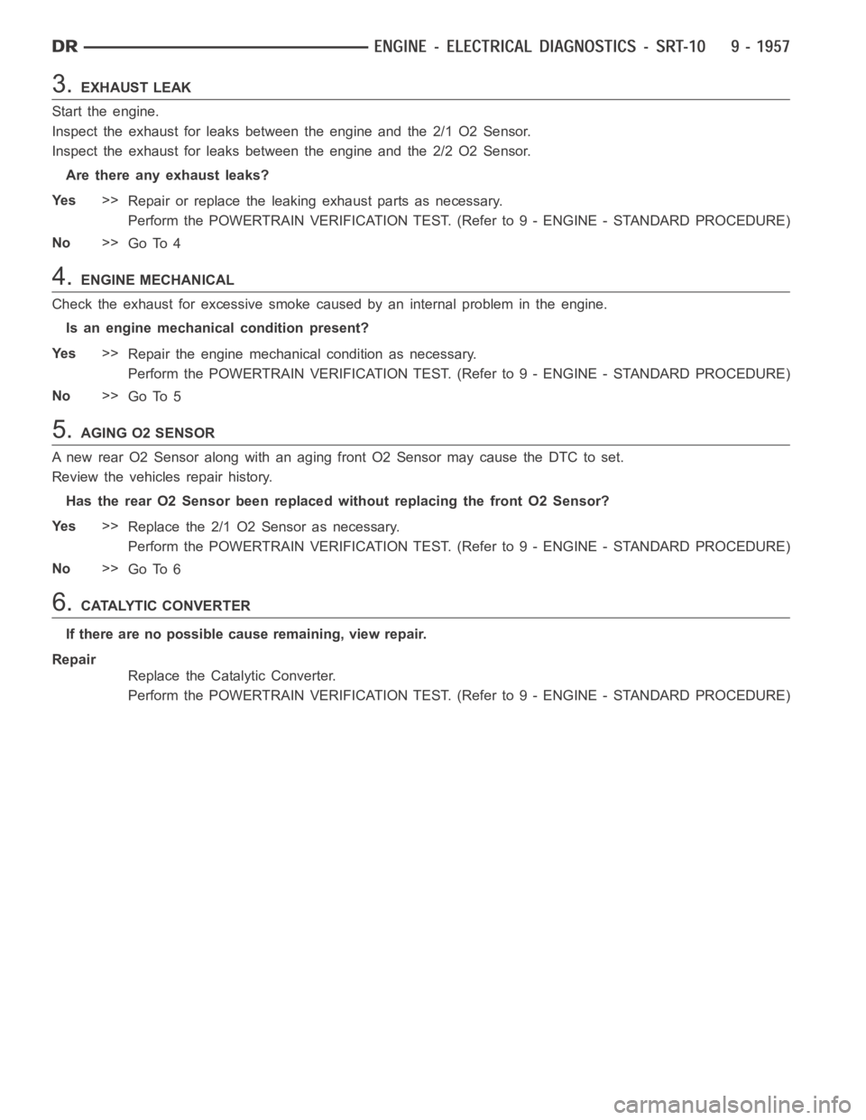
3.EXHAUST LEAK
Start the engine.
Inspect the exhaust for leaks between the engine and the 2/1 O2 Sensor.
Inspect the exhaust for leaks between the engine and the 2/2 O2 Sensor.
Are there any exhaust leaks?
Ye s>>
Repair or replace the leaking exhaust parts as necessary.
Perform the POWERTRAIN VERIFICATION TEST. (Refer to 9 - ENGINE - STANDARD PROCEDURE)
No>>
Go To 4
4.ENGINE MECHANICAL
Check the exhaust for excessive smoke caused by an internal problem in the engine.
Is an engine mechanical condition present?
Ye s>>
Repair the engine mechanical condition as necessary.
Perform the POWERTRAIN VERIFICATION TEST. (Refer to 9 - ENGINE - STANDARD PROCEDURE)
No>>
Go To 5
5.AGING O2 SENSOR
A new rear O2 Sensor along with an aging front O2 Sensor may cause the DTC to set.
Review the vehicles repair history.
Has the rear O2 Sensor been replaced without replacing the front O2 Sensor?
Ye s>>
Replace the 2/1 O2 Sensor as necessary.
Perform the POWERTRAIN VERIFICATION TEST. (Refer to 9 - ENGINE - STANDARD PROCEDURE)
No>>
Go To 6
6.CATALYTIC CONVERTER
If there are no possible cause remaining, view repair.
Repair
Replace the Catalytic Converter.
Perform the POWERTRAIN VERIFICATION TEST. (Refer to 9 - ENGINE - STANDARD PROCEDURE)
Page 2136 of 5267
EXHAUST SYSTEM
TABLE OF CONTENTS
page page
EXHAUST SYSTEM
DESCRIPTION
GAS ENGINES ............................... 2
5.9L DIESEL ................................. 3
DIAGNOSIS AND TESTING
GAS ENGINE ................................ 4
DIESEL ENGINE............................. 5
SPECIFICATIONS
TORQUE .................................... 5
SPECIAL TOOLS ............................... 7
CONVERTER-CATALYTIC
DESCRIPTION ................................. 8
OPERATION ................................... 8
REMOVAL
3.7L/4.7L ENGINE ............................ 8
5.7L ENGINE ................................ 9
5.9L DIESEL ENGINE ......................... 9
8.3L ENGINE ............................... 10
INSPECTION ................................. 10
INSTALLATION
3.7L/4.7L ENGINE ........................... 10
5.7L ENGINE ............................... 11
5.9L ENGINE DIESEL ........................ 11
8.3L ENGINE ............................... 12
PIPE EXHAUST
REMOVAL
3.7L/4.7L/5.7L ENGINE ...................... 13
5.9L DIESEL ................................ 13
8.3L ENGINE ............................... 13
INSPECTION ................................. 14
INSTALLATION
3.7L/4.7L/5.7L ENGINE ...................... 14
5.9L DIESEL ................................ 14
8.3L ENGINE ............................... 15
HEAT SHIELDS
DESCRIPTION ................................ 16
REMOVAL .................................... 16
INSTALLATION ............................... 17
MUFFLER
REMOVAL
3.7L/4.7L/5.7L ENGINE ...................... 19
8.3L ENGINE ............................... 195.9L DIESEL ENGINE....................... 20
INSTALLATION
3.7L/4.7L/5.7L ENGINE ...................... 20
8.3L ENGINE ............................... 21
5.9L DIESEL ENGINE....................... 21
TAILPIPE
REMOVAL
3.7L/4.7L/5.7L ENGINE ...................... 22
5.9L DIESEL................................ 22
8.3L ENGINE ............................... 23
INSPECTION ................................. 23
INSTALLATION
3.7L/4.7L/5.7L ENGINE ...................... 23
5.9L DIESEL................................ 24
8.3L ENGINE ............................... 24
TURBOCHARGER SYSTEM
DIAGNOSIS AND TESTING
TURBOCHARGER BOOST PRESSURE ....... 25
TURBOCHARGER
DESCRIPTION ................................ 26
OPERATION .................................. 27
REMOVAL
TURBOCHARGER .......................... 29
TURBOCHARGER OIL DRAIN TUBE .......... 30
CLEANING ................................... 30
INSPECTION ................................. 30
INSTALLATION
TURBOCHARGER .......................... 31
TURBOCHARGER OIL DRAIN TUBE .......... 32
WASTEGATE - ELECTRONIC ACTUATOR
REMOVAL .................................... 33
INSTALLATION ............................... 33
CHARGE AIR COOLER AND PLUMBING
DESCRIPTION ................................ 34
OPERATION .................................. 34
DIAGNOSIS AND TESTING
CHARGE AIR COOLER SYSTEM - LEAKS.... 35
REMOVAL .................................... 35
CLEANING ................................... 36
INSPECTION ................................. 36
INSTALLATION ............................... 36
Page 2138 of 5267
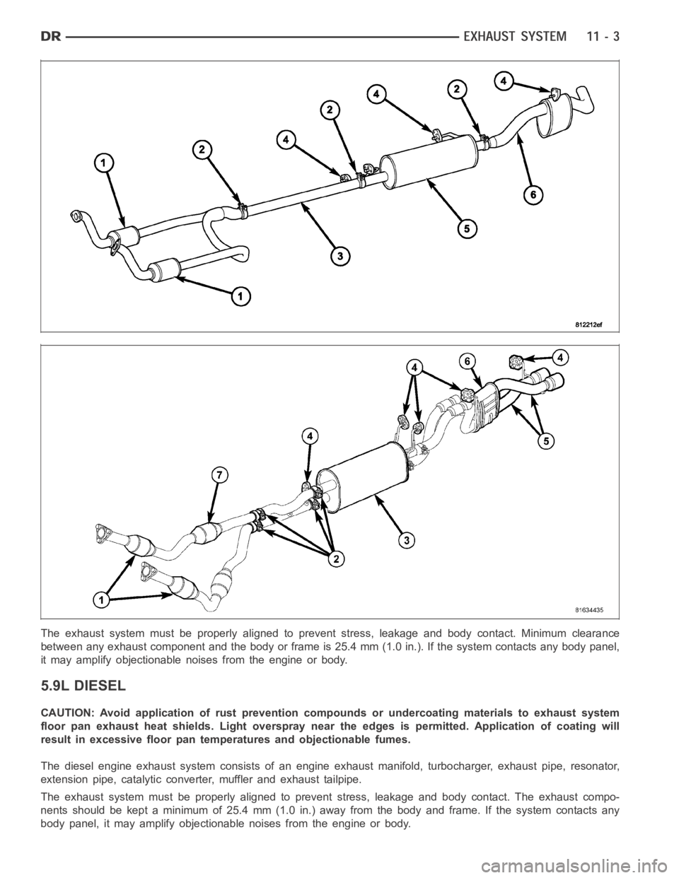
The exhaust system must be properly aligned to prevent stress, leakage andbody contact. Minimum clearance
between any exhaust component and the body or frame is 25.4 mm (1.0 in.). If the system contacts any body panel,
it may amplify objectionable noises from the engine or body.
5.9L DIESEL
CAUTION: Avoid application of rust prevention compounds or undercoatingmaterials to exhaust system
floor pan exhaust heat shields. Light overspray near the edges is permitted. Application of coating will
result in excessive floor pan temperatures and objectionable fumes.
The diesel engine exhaust system consists of an engine exhaust manifold, turbocharger, exhaust pipe, resonator,
extension pipe, catalytic converter, muffler and exhaust tailpipe.
The exhaust system must be properly aligned to prevent stress, leakage andbody contact. The exhaust compo-
nents should be kept a minimum of 25.4 mm (1.0 in.) away from the body and frame. If the system contacts any
body panel, it may amplify objectionable noises from the engine or body.
Page 2139 of 5267
DIAGNOSIS AND TESTING
GAS ENGINE
EXHAUST SYSTEM DIAGNOSIS CHART
CONDITION POSSIBLE CAUSE CORRECTION
EXCESSIVE EXHAUST NOISE OR
LEAKING EXHAUST GASES1. Leaks at pipe joints. 1. Tighten clamps/bolts at leaking
joints.
2. Rusted or blown out muffler. 2. Replace muffler. Inspect exhaust
system.
3. Broken or rusted out exhaust
pipe.3. Replace exhaust pipe.
4. Exhaust pipe leaking at manifold
flange.4. Tighten/replace flange attaching
nuts/bolts.
5. Exhaust manifold cracked or
broken.5. Replace exhaust manifold.
6. Leak between exhaust manifold
and cylinder head.6. Tighten exhaust manifold to
cylinder head bolts.
7. Catalytic converter rusted or
blown out.7. Replace catalytic converter assy.
8. Restriction in exhaust system. 8. Remove restriction, if possible.
Replace restricted part if necessary.
CAUTION:
When servicing and replacing exhaust system components, disconnect the oxygen sensor connector(s). Allowing
the exhaust to hang by the oxygen sensor wires will damage the harness and/or sensor.
Page 2143 of 5267
CONVERTER-CATALYTIC
DESCRIPTION
WARNING: THE NORMAL OPERATING TEMPERATURE OF THE EXHAUST SYSTEM IS VERY HIGH. THERE-
FORE, NEVER WORK AROUND OR ATTEMPT TO SERVICE ANY PART OF THE EXHAUST SYSTEMUNTIL IT
IS COOLED. SPECIAL CARE SHOULD BE TAKEN WHEN WORKING NEAR THE CATALYTIC CONVERTER.
THE TEMPERATURE OF THE CONVERTER RISES TO A HIGH LEVEL AFTER A SHORT PERIOD OFENGINE
OPERATION TIME.
CAUTION: DO NOT remove spark plug wires from plugs or by any other means short out cylinders. Failure
of the catalytic converter can occur due to a temperature increase caused by unburned fuel passing
through the converter.
The stainless steel catalytic converter body is designed to last the life of the vehicle. Excessive heat can result in
bulging or other distortion, but excessive heat will not be the fault of theconverter. If unburned fuel enters the con-
verter, overheating may occur. If a converter is heat-damaged, correct the cause of the damage at the same time
the converter is replaced. Also, inspect all other components of the exhaust system for heat damage.
Unleaded gasoline must be used to avoid contaminating the catalyst core.
50 State emission vehicles incorporate two mini catalytic converters located after the exhaust manifolds and before
the inline catalytic converter.
OPERATION
The catalytic converter captures and burns any unburned fuel mixture exiting the combustion chambers during the
exhaust stroke of the engine. This process aids in reducing emissions output.
REMOVAL
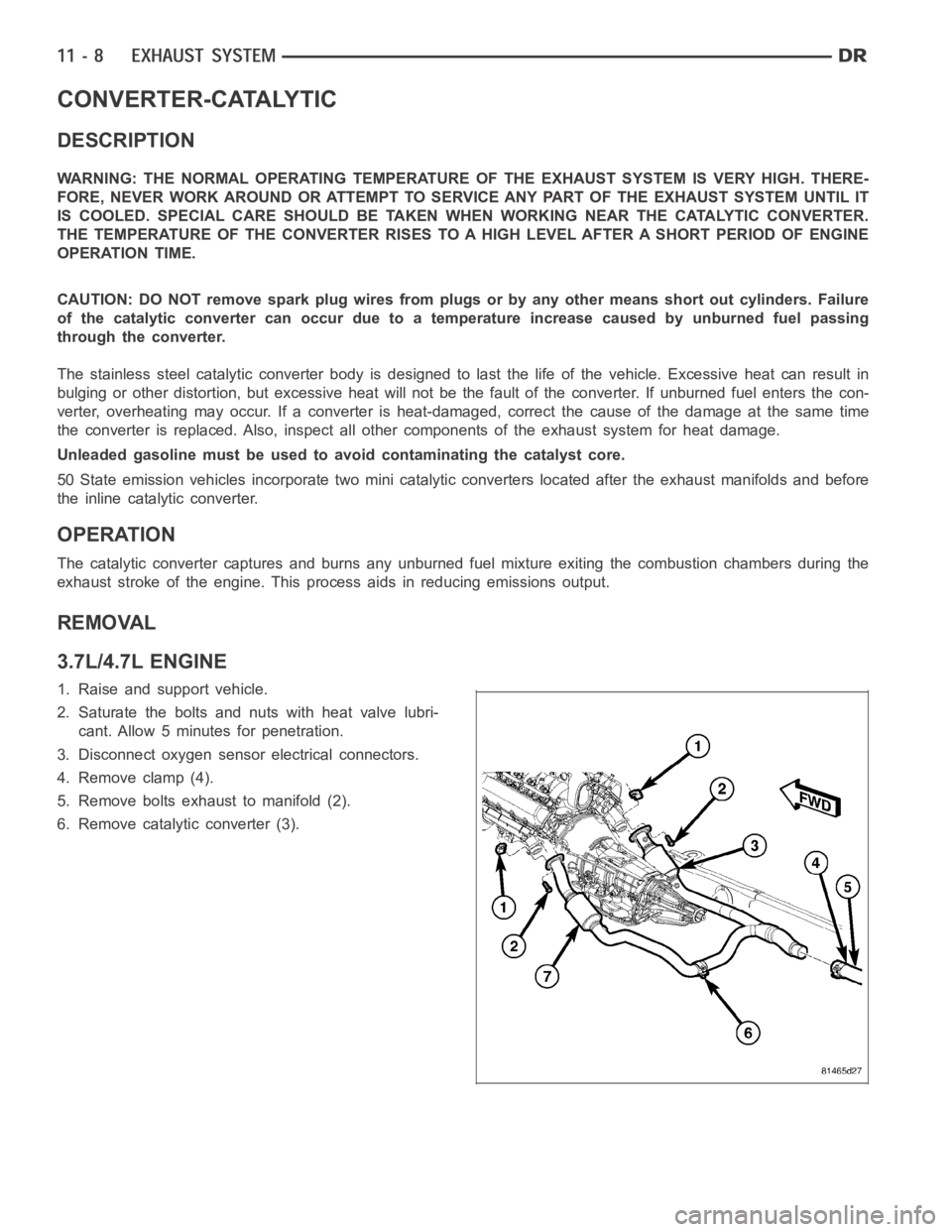
3.7L/4.7L ENGINE
1. Raise and support vehicle.
2. Saturate the bolts and nuts with heat valve lubri-
cant. Allow 5 minutes for penetration.
3. Disconnect oxygen sensor electrical connectors.
4. Remove clamp (4).
5. Remove bolts exhaust to manifold (2).
6. Remove catalytic converter (3).