Page 2144 of 5267
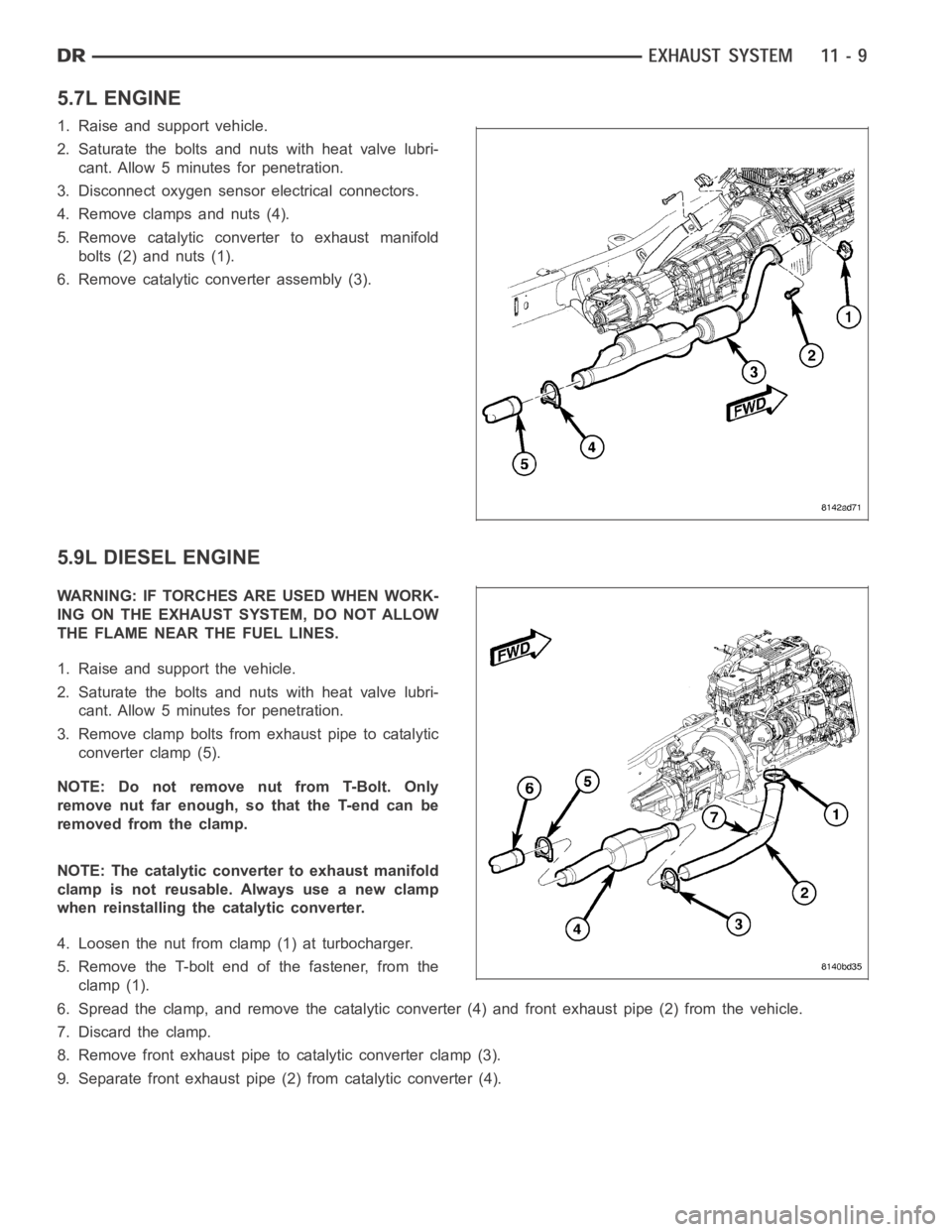
5.7L ENGINE
1. Raise and support vehicle.
2. Saturate the bolts and nuts with heat valve lubri-
cant. Allow 5 minutes for penetration.
3. Disconnect oxygen sensor electrical connectors.
4. Remove clamps and nuts (4).
5. Remove catalytic converter to exhaust manifold
bolts (2) and nuts (1).
6. Remove catalytic converter assembly (3).
5.9L DIESEL ENGINE
WARNING: IF TORCHES ARE USED WHEN WORK-
ING ON THE EXHAUST SYSTEM, DO NOT ALLOW
THE FLAME NEAR THE FUEL LINES.
1. Raise and support the vehicle.
2. Saturate the bolts and nuts with heat valve lubri-
cant. Allow 5 minutes for penetration.
3. Remove clamp bolts from exhaust pipe to catalytic
converter clamp (5).
NOTE: Do not remove nut from T-Bolt. Only
remove nut far enough, so that the T-end can be
removed from the clamp.
NOTE: The catalytic converter to exhaust manifold
clamp is not reusable. Always use a new clamp
when reinstalling the catalytic converter.
4. Loosen the nut from clamp (1) at turbocharger.
5. Remove the T-bolt end of the fastener, from the
clamp (1).
6. Spread the clamp, and remove the catalytic converter (4) and front exhaust pipe (2) from the vehicle.
7. Discard the clamp.
8. Remove front exhaust pipe to catalytic converter clamp (3).
9. Separate front exhaust pipe (2) from catalytic converter (4).
Page 2145 of 5267
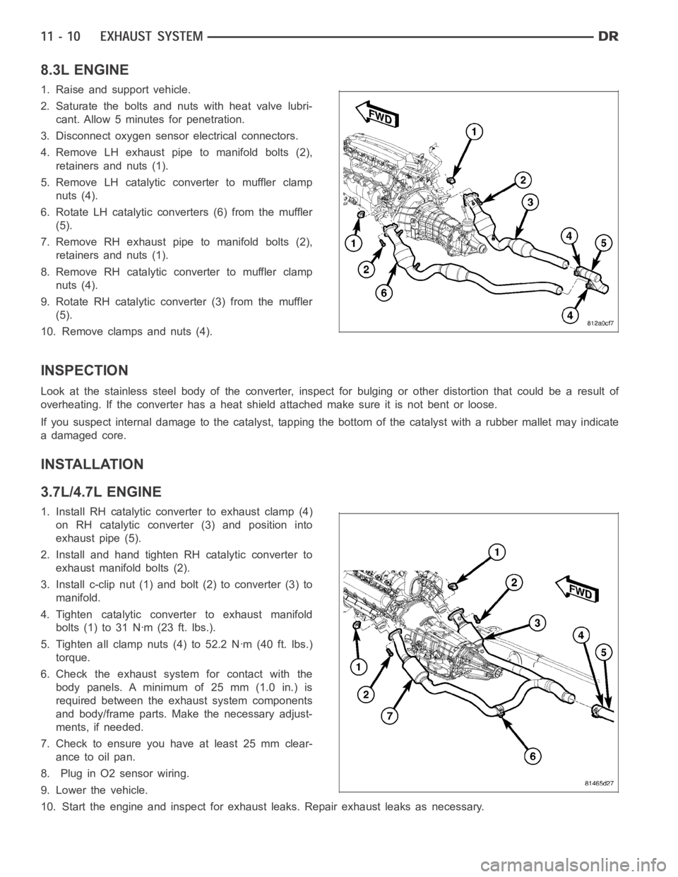
8.3L ENGINE
1. Raise and support vehicle.
2. Saturate the bolts and nuts with heat valve lubri-
cant. Allow 5 minutes for penetration.
3. Disconnect oxygen sensor electrical connectors.
4. Remove LH exhaust pipe to manifold bolts (2),
retainers and nuts (1).
5. Remove LH catalytic converter to muffler clamp
nuts (4).
6. Rotate LH catalytic converters (6) from the muffler
(5).
7. Remove RH exhaust pipe to manifold bolts (2),
retainers and nuts (1).
8. Remove RH catalytic converter to muffler clamp
nuts (4).
9. Rotate RH catalytic converter (3) from the muffler
(5).
10. Remove clamps and nuts (4).
INSPECTION
Look at the stainless steel body of the converter, inspect for bulging or other distortion that could be a result of
overheating. If the converter has a heat shield attached make sure it is notbent or loose.
If you suspect internal damage to the catalyst, tapping the bottom of the catalyst with a rubber mallet may indicate
a damaged core.
INSTALLATION
3.7L/4.7L ENGINE
1. Install RH catalytic converter to exhaust clamp (4)
on RH catalytic converter (3) and position into
exhaust pipe (5).
2. Install and hand tighten RH catalytic converter to
exhaust manifold bolts (2).
3. Install c-clip nut (1) and bolt (2) to converter (3) to
manifold.
4. Tighten catalytic converter to exhaust manifold
bolts(1)to31Nꞏm(23ft.lbs.).
5. Tighten all clamp nuts (4) to 52.2 Nꞏm (40 ft. lbs.)
torque.
6. Check the exhaust system for contact with the
body panels. A minimum of 25 mm (1.0 in.) is
required between the exhaust system components
and body/frame parts. Make the necessary adjust-
ments, if needed.
7. Check to ensure you have at least 25 mm clear-
ance to oil pan.
8. Plug in O2 sensor wiring.
9. Lower the vehicle.
10. Start the engine and inspect for exhaust leaks. Repair exhaust leaks asnecessary.
Page 2146 of 5267
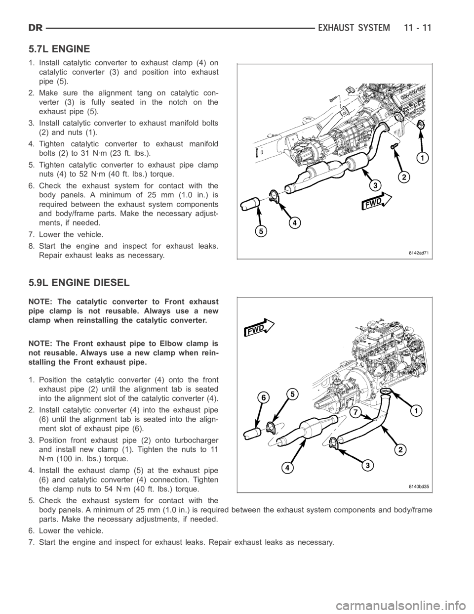
5.7L ENGINE
1. Install catalytic converter to exhaust clamp (4) on
catalytic converter (3) and position into exhaust
pipe (5).
2. Make sure the alignment tang on catalytic con-
verter (3) is fully seated in the notch on the
exhaust pipe (5).
3. Install catalytic converter to exhaust manifold bolts
(2) and nuts (1).
4. Tighten catalytic converter to exhaust manifold
bolts(2)to31Nꞏm(23ft.lbs.).
5. Tighten catalytic converter to exhaust pipe clamp
nuts (4) to 52 Nꞏm (40 ft. lbs.) torque.
6. Check the exhaust system for contact with the
body panels. A minimum of 25 mm (1.0 in.) is
required between the exhaust system components
and body/frame parts. Make the necessary adjust-
ments, if needed.
7. Lower the vehicle.
8. Start the engine and inspect for exhaust leaks.
Repair exhaust leaks as necessary.
5.9L ENGINE DIESEL
NOTE: The catalytic converter to Front exhaust
pipe clamp is not reusable. Always use a new
clamp when reinstalling the catalytic converter.
NOTE: The Front exhaust pipe to Elbow clamp is
not reusable. Always use a new clamp when rein-
stalling the Front exhaust pipe.
1. Position the catalytic converter (4) onto the front
exhaust pipe (2) until the alignment tab is seated
into the alignment slot of the catalytic converter (4).
2. Install catalytic converter (4) into the exhaust pipe
(6) until the alignment tab is seated into the align-
ment slot of exhaust pipe (6).
3. Position front exhaust pipe (2) onto turbocharger
and install new clamp (1). Tighten the nuts to 11
Nꞏm (100 in. lbs.) torque.
4. Install the exhaust clamp (5) at the exhaust pipe
(6) and catalytic converter (4) connection. Tighten
the clamp nuts to 54 Nꞏm (40 ft. lbs.) torque.
5. Check the exhaust system for contact with the
body panels. A minimum of 25 mm (1.0 in.) is required between the exhaust system components and body/frame
parts. Make the necessary adjustments, if needed.
6. Lower the vehicle.
7. Start the engine and inspect for exhaust leaks. Repair exhaust leaks as necessary.
Page 2147 of 5267
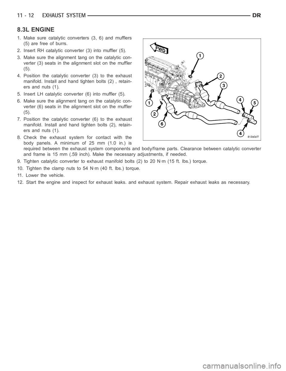
8.3L ENGINE
1. Make sure catalytic converters (3, 6) and mufflers
(5) are free of burrs.
2. Insert RH catalytic converter (3) into muffler (5).
3. Make sure the alignment tang on the catalytic con-
verter (3) seats in the alignment slot on the muffler
(5).
4. Position the catalytic converter (3) to the exhaust
manifold. Install and hand tighten bolts (2) , retain-
ers and nuts (1).
5. Insert LH catalytic converter (6) into muffler (5).
6. Make sure the alignment tang on the catalytic con-
verter (6) seats in the alignment slot on the muffler
(5).
7. Position the catalytic converter (6) to the exhaust
manifold. Install and hand tighten bolts (2), retain-
ers and nuts (1).
8. Check the exhaust system for contact with the
body panels. A minimum of 25 mm (1.0 in.) is
required between the exhaust system components and body/frame parts. Clearance between catalytic converter
and frame is 15 mm (.59 inch). Make the necessary adjustments, if needed.
9. Tighten catalytic converter to exhaust manifold bolts (2) to 20 Nꞏm (15 ft. lbs.) torque.
10. Tighten the clamp nuts to 54 Nꞏm (40 ft. lbs.) torque.
11. Lower the vehicle.
12. Start the engine and inspect for exhaust leaks. and exhaust system. Repair exhaust leaks as necessary.
Page 2154 of 5267
MUFFLER
REMOVAL
3.7L/4.7L/5.7L ENGINE
1. Raise and support the vehicle.
2. Saturate the clamp nuts with heat valve lubricant.
Allow 5 minutes for penetration.
3. Disconnect the muffler hangers.
4. Remove clamps and nuts.
5. Remove the muffler.
8.3L ENGINE
1. Raise and support the vehicle.
2. Saturate the clamp nuts with heat valve lubricant.
Allow 5 minutes for penetration.
3. Remove exhaust pipes (Refer to 11 - EXHAUST
SYSTEM/EXHAUST PIPE - REMOVAL).
4. Saturate the clamp nuts with heat valve lubricant.
Allow 5 minutes for penetration.
5. Disconnect the muffler hangers.
6. Remove muffler-to-catalytic converter clamp nuts.
7. Remove the muffler.
Page 2156 of 5267
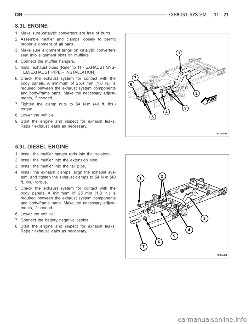
8.3L ENGINE
1. Make sure catalytic converters are free of burrs.
2. Assemble muffler and clamps loosely to permit
proper alignment of all parts.
3. Make sure alignment tangs on catalytic converters
seat into alignment slots on mufflers.
4. Connect the muffler hangers.
5. Install exhaust pipes (Refer to 11 - EXHAUST SYS-
TEM/EXHAUST PIPE - INSTALLATION).
6. Check the exhaust system for contact with the
body panels. A minimum of 25.4 mm (1.0 in.) is
required between the exhaust system components
and body/frame parts. Make the necessary adjust-
ments, if needed.
7.Tightentheclampnutsto54Nꞏm(40ft.lbs.)
torque.
8. Lower the vehicle.
9. Start the engine and inspect for exhaust leaks.
Repair exhaust leaks as necessary.
5.9L DIESEL ENGINE
1. Install the muffler hanger rods into the isolators.
2. Install the muffler into the extension pipe.
3. Install the muffler into the tail pipe.
4. Install the exhaust clamps, align the exhaust sys-
tem, and tighten the exhaust clamps to 54 Nꞏm (40
ft. lbs.) torque.
5. Check the exhaust system for contact with the
body panels. A minimum of 25 mm (1.0 in.) is
required between the exhaust system components
and body/frame parts. Make the necessary adjust-
ments, if needed.
6. Lower the vehicle.
7. Connect the battery negative cables.
8. Start the engine and inspect for exhaust leaks.
Repair exhaust leaks as necessary.
Page 2321 of 5267
SENSOR - OXYGEN
DESCRIPTION
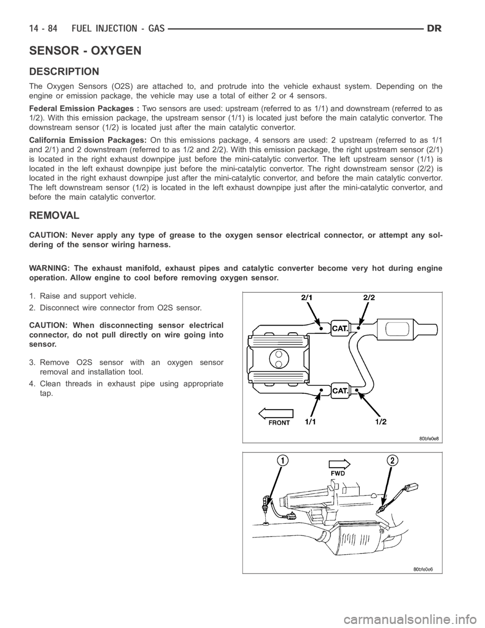
The Oxygen Sensors (O2S) are attached to, and protrude into the vehicle exhaust system. Depending on the
engine or emission package, the vehicle may use a total of either 2 or 4 sensors.
Federal Emission Packages :Two sensors are used: upstream (referred to as 1/1) and downstream (referred to as
1/2). With this emission package, the upstream sensor (1/1) is located just before the main catalytic convertor. The
downstream sensor (1/2) is located just after the main catalytic convertor.
California Emission Packages:On this emissions package, 4 sensors are used: 2 upstream (referred to as 1/1
and 2/1) and 2 downstream (referred to as 1/2 and 2/2). With this emission package, the right upstream sensor (2/1)
is located in the right exhaust downpipe just before the mini-catalytic convertor. The left upstream sensor (1/1) is
located in the left exhaust downpipe just before the mini-catalytic convertor. The right downstream sensor (2/2) is
located in the right exhaust downpipe just after the mini-catalytic convertor, and before the main catalytic convertor.
The left downstream sensor (1/2) is located in the left exhaust downpipe just after the mini-catalytic convertor, and
before the main catalytic convertor.
REMOVAL
CAUTION: Never apply any type of grease to the oxygen sensor electrical connector, or attempt any sol-
dering of the sensor wiring harness.
WARNING: The exhaust manifold, exhaust pipes and catalytic converter become very hot during engine
operation. Allow engine to cool before removing oxygen sensor.
1. Raise and support vehicle.
2. Disconnect wire connector from O2S sensor.
CAUTION: When disconnecting sensor electrical
connector, do not pull directly on wire going into
sensor.
3. Remove O2S sensor with an oxygen sensor
removal and installation tool.
4. Clean threads in exhaust pipe using appropriate
tap.
Page 2926 of 5267
11. Disconnect wires from the solenoid/pressure
switch assembly.
12. Remove the bolts holding the exhaust crossover
pipe to the pre-catalytic converter pipe flanges (1).
13. Remove the bolts holding the exhaust crossover
pipe to the catalytic converter flange.
14. Disconnect gearshift cable (1) from transmission
manual valve lever (3).
15. Disengage the shift cable (1) from the cable sup-
port bracket (2).