2006 DODGE RAM SRT-10 check engine
[x] Cancel search: check enginePage 378 of 5267
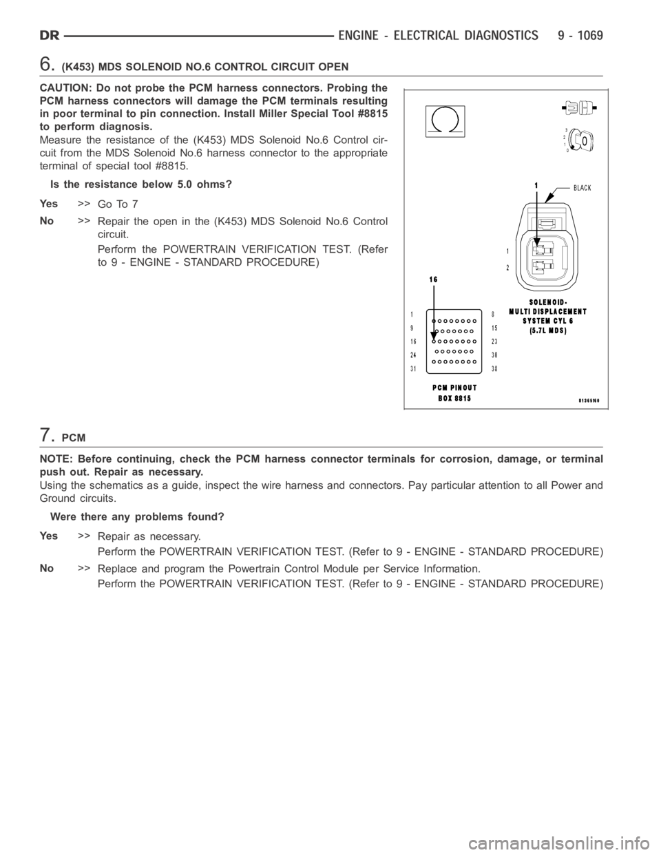
6.(K453) MDS SOLENOID NO.6 CONTROL CIRCUIT OPEN
CAUTION: Do not probe the PCM harness connectors. Probing the
PCM harness connectors will damage the PCM terminals resulting
in poor terminal to pin connection. Install Miller Special Tool #8815
to perform diagnosis.
Measure the resistance of the (K453) MDS Solenoid No.6 Control cir-
cuit from the MDS Solenoid No.6 harness connector to the appropriate
terminal of special tool #8815.
Is the resistance below 5.0 ohms?
Ye s>>
Go To 7
No>>
Repair the open in the (K453) MDS Solenoid No.6 Control
circuit.
Perform the POWERTRAIN VERIFICATION TEST. (Refer
to 9 - ENGINE - STANDARD PROCEDURE)
7.PCM
NOTE: Before continuing, check the PCM harness connector terminals for corrosion, damage, or terminal
push out. Repair as necessary.
Using the schematics as a guide, inspect the wire harness and connectors. Pay particular attention to all Power and
Ground circuits.
Were there any problems found?
Ye s>>
Repair as necessary.
Perform the POWERTRAIN VERIFICATION TEST. (Refer to 9 - ENGINE - STANDARD PROCEDURE)
No>>
Replace and program the Powertrain Control Module per Service Information.
Perform the POWERTRAIN VERIFICATION TEST. (Refer to 9 - ENGINE - STANDARD PROCEDURE)
Page 381 of 5267
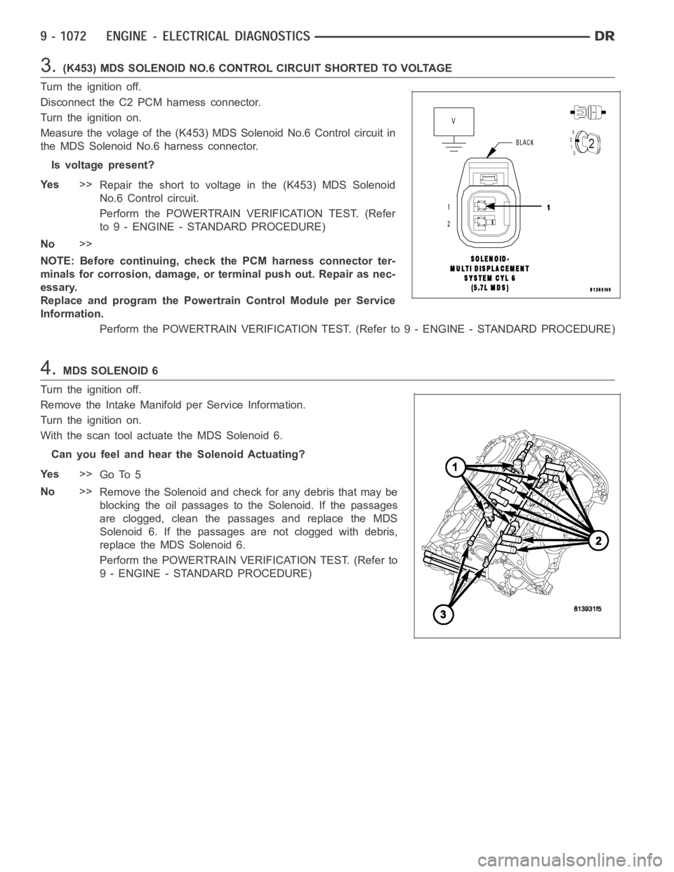
3.(K453) MDS SOLENOID NO.6 CONTROL CIRCUIT SHORTED TO VOLTAGE
Turn the ignition off.
Disconnect the C2 PCM harness connector.
Turn the ignition on.
Measure the volage of the (K453) MDS Solenoid No.6 Control circuit in
the MDS Solenoid No.6 harness connector.
Is voltage present?
Ye s>>
Repair the short to voltage in the (K453) MDS Solenoid
No.6 Control circuit.
Perform the POWERTRAIN VERIFICATION TEST. (Refer
to 9 - ENGINE - STANDARD PROCEDURE)
No>>
NOTE: Before continuing, check the PCM harness connector ter-
minals for corrosion, damage, or terminal push out. Repair as nec-
essary.
Replace and program the Powertrain Control Module per Service
Information.
Perform the POWERTRAIN VERIFICATION TEST. (Refer to 9 - ENGINE - STANDARD PROCEDURE)
4.MDS SOLENOID 6
Turn the ignition off.
Remove the Intake Manifold per Service Information.
Turn the ignition on.
With the scan tool actuate the MDS Solenoid 6.
Can you feel and hear the Solenoid Actuating?
Ye s>>
Go To 5
No>>
Remove the Solenoid and check for any debris that may be
blocking the oil passages to the Solenoid. If the passages
are clogged, clean the passages and replace the MDS
Solenoid 6. If the passages are not clogged with debris,
replace the MDS Solenoid 6.
Perform the POWERTRAIN VERIFICATION TEST. (Refer to
9 - ENGINE - STANDARD PROCEDURE)
Page 386 of 5267
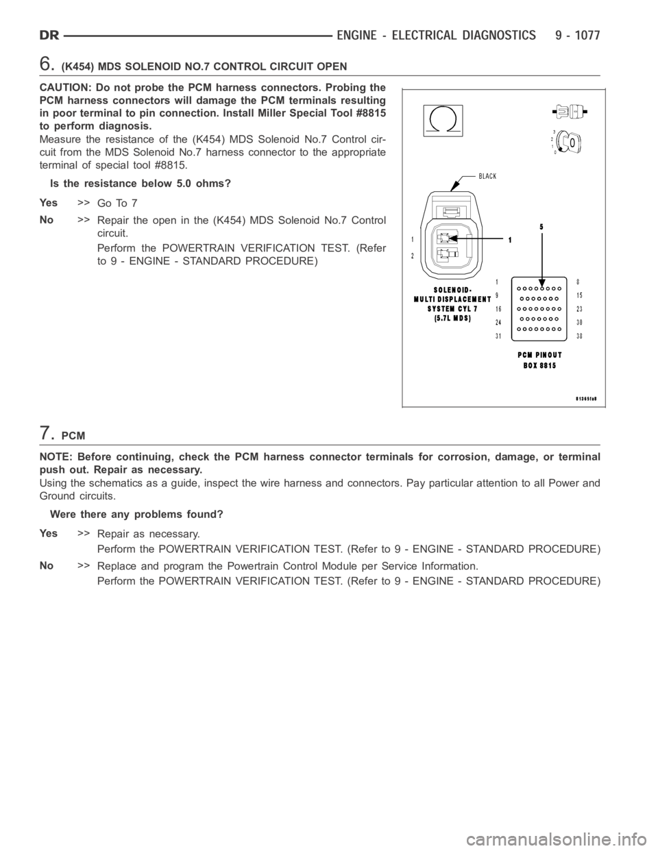
6.(K454) MDS SOLENOID NO.7 CONTROL CIRCUIT OPEN
CAUTION: Do not probe the PCM harness connectors. Probing the
PCM harness connectors will damage the PCM terminals resulting
in poor terminal to pin connection. Install Miller Special Tool #8815
to perform diagnosis.
Measure the resistance of the (K454) MDS Solenoid No.7 Control cir-
cuit from the MDS Solenoid No.7 harness connector to the appropriate
terminal of special tool #8815.
Is the resistance below 5.0 ohms?
Ye s>>
Go To 7
No>>
Repair the open in the (K454) MDS Solenoid No.7 Control
circuit.
Perform the POWERTRAIN VERIFICATION TEST. (Refer
to 9 - ENGINE - STANDARD PROCEDURE)
7.PCM
NOTE: Before continuing, check the PCM harness connector terminals for corrosion, damage, or terminal
push out. Repair as necessary.
Using the schematics as a guide, inspect the wire harness and connectors. Pay particular attention to all Power and
Ground circuits.
Were there any problems found?
Ye s>>
Repair as necessary.
Perform the POWERTRAIN VERIFICATION TEST. (Refer to 9 - ENGINE - STANDARD PROCEDURE)
No>>
Replace and program the Powertrain Control Module per Service Information.
Perform the POWERTRAIN VERIFICATION TEST. (Refer to 9 - ENGINE - STANDARD PROCEDURE)
Page 389 of 5267
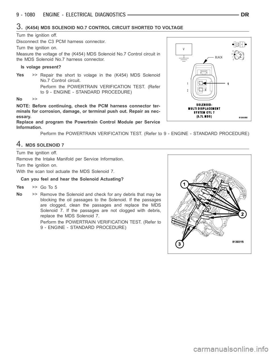
3.(K454) MDS SOLENOID NO.7 CONTROL CIRCUIT SHORTED TO VOLTAGE
Turn the ignition off.
Disconnect the C3 PCM harness connector.
Turn the ignition on.
Measure the voltage of the (K454) MDS Solenoid No.7 Control circuit in
the MDS Solenoid No.7 harness connector.
Is volage present?
Ye s>>
Repair the short to volage in the (K454) MDS Solenoid
No.7 Control circuit.
Perform the POWERTRAIN VERIFICATION TEST. (Refer
to 9 - ENGINE - STANDARD PROCEDURE)
No>>
NOTE: Before continuing, check the PCM harness connector ter-
minals for corrosion, damage, or terminal push out. Repair as nec-
essary.
Replace and program the Powertrain Control Module per Service
Information.
Perform the POWERTRAIN VERIFICATION TEST. (Refer to 9 - ENGINE - STANDARD PROCEDURE)
4.MDS SOLENOID 7
Turn the ignition off.
Remove the Intake Manifold per Service Information.
Turn the ignition on.
With the scan tool actuate the MDS Solenoid 7.
Can you feel and hear the Solenoid Actuating?
Ye s>>
Go To 5
No>>
Remove the Solenoid and check for any debris that may be
blocking the oil passages to the Solenoid. If the passages
are clogged, clean the passages and replace the MDS
Solenoid 7. If the passages are not clogged with debris,
replace the MDS Solenoid 7.
Perform the POWERTRAIN VERIFICATION TEST. (Refer to
9 - ENGINE - STANDARD PROCEDURE)
Page 391 of 5267

P3497-MDS RATIONALITY BANK 2
For a complete wiring diagramRefer to Section 8W.
Theory of Operation
When all criteria has been met, power is supplied to each MDS Solenoid when the engine is making a transition
from 8 cylinder mode to 4 cylinder mode. By actuating the solenoid, oil pressure is raised to the pair of lifters that
coincide with each particular solenoid. The oil pressure pushes in the locking pins that allows the lifter to collapse,
decoupling the valves and camshaft.
When Monitored:
Transition from 8 to 4 cylinder mode.
Set Condition:
O2 sensor readings on Bank 2 side indicate a lean condition while in 4 cylinder mode. One trip fault.
Possible Causes
INSUFFICIENT OIL PRESSURE ACTING ON THE LIFTER LOCKING PINS
OIL PASSAGES RESTRICTED
LIFTER
MDS SOLENOID
Always perform the Pre-Diagnostic Troubleshooting procedure before proceeding (Refer to 9 - ENGINE -
DIAGNOSIS AND TESTING).
Diagnostic Test
1.ACTIVE DTC
Ignition on, engine not running.
With a scan tool, read DTCs.
NOTE: Diagnose any Oil Pressure DTCs before continuing.
Is the DTC active at this time?
Ye s>>
Go To 2
No>>
Refer to the INTERMITTENT CONDITION Diagnostic Procedure.
Perform the POWERTRAIN VERIFICATION TEST. (Refer to 9 - ENGINE - STANDARD PROCEDURE)
2.MDS SOLENOID 4
Turn the ignition off.
Remove the Intake Manifold per Service Information.
Turn the ignition on.
With the scan tool actuate the MDS Solenoid 4.
Can you feel and hear the Solenoid Actuating?
Ye s>>
Go To 3
No>>
Remove the Solenoid and check for any debris that may be blocking the oil passages to the Solenoid.
If the passages are clogged, clean the passages and replace the MDS Solenoid4.Ifthepassagesare
not clogged with debris, replace the MDS Solenoid 4.
Perform the POWERTRAIN VERIFICATION TEST. (Refer to 9 - ENGINE - STANDARD PROCEDURE)
Page 392 of 5267
3.MDS SOLENOID 6
With the scan tool actuate the MDS Solenoid 6.
Can you feel and hear the Solenoid Actuating?
Ye s>>
Go To 4
No>>
Remove the Solenoid and check for any debris that may be blocking the oil passages to the Solenoid.
If the passages are restricted, clean the passages and replace the MDS Solenoid 6. If the passages are
unable to be cleaned out, replacing the engine block may be necessary. If the passages are not clogged
with debris, replace the MDS Solenoid 6.
Perform the POWERTRAIN VERIFICATION TEST. (Refer to 9 - ENGINE - STANDARD PROCEDURE)
4.OIL PASSAGES RESTRICTED
Turn the ignition off.
Remove both Solenoids on Bank 2 of the engine block.
Remove the Bank 2 Cylinder Head per Service Information.
Remove the each pair of lifters for Cylinders 4 and 6.
Inspect the oil passages to the Solenoids and from the Solenoids to the lifters.
Are the passages blocked?
Ye s>>
Clean the oil passages as necessary. If the entire engine is restricted disassembly of the entire engine
block may be necessary.
Perform the POWERTRAIN VERIFICATION TEST. (Refer to 9 - ENGINE - STANDARD PROCEDURE)
No>>
Replace both sets of lifters if no other possible causes remain.
Perform the POWERTRAIN VERIFICATION TEST. (Refer to 9 - ENGINE - STANDARD PROCEDURE)
Page 395 of 5267
U0101-LOST COMMUNICATION WITH TCM
For a complete wiring diagramRefer to Section 8W.
When Monitored:
Ignition run time is greater than 1 second. Battery voltage between 9 and 16volts. Engine run time greater
than 3 seconds.
Set Condition:
The PCM doesn’t receive a Bus Message from the Transmission Control Modulefor 7 consecutive seconds.
One trip failure. The circuit is continuously monitored.
Possible Causes
PCM FUSED IGNITION SWITCH OUTPUT CIRCUIT CHECK
BUS FAILURE OPEN OR SHORTED CONDITION
PCI BUS UNABLE TO COMMUNICATE WITH THE SCAN TOOL
PCM
Refer to 8 - ELECTRICAL/ELECTRONIC CONTROL MODULES - DIAGNOSIS AND TESTING for diagnostic
procedures and for further possible causes.
Diagnostic Test
1.ACTIVE DTC
Ignition on, engine not running.
With the scan tool, erase DTCs.
Cycle the ignition key on and off several times. Leaving the ignition on forat least 20 seconds.
With the scan tool, read DTCs.
Does the DTC reset?
Ye s>>
Go To 2
No>>
Refer to the INTERMITTENT CONDITIONSymptom (Diagnostic Procedure).
Perform the POWERTRAIN VERIFICATION TEST. (Refer to 9 - ENGINE - STANDARD PROCEDURE)
2.PCM FUSED IGNITION SWITCH OUTPUT CIRCUIT
Turn the ignition off.
Disconnect the C1 PCM harness connector.
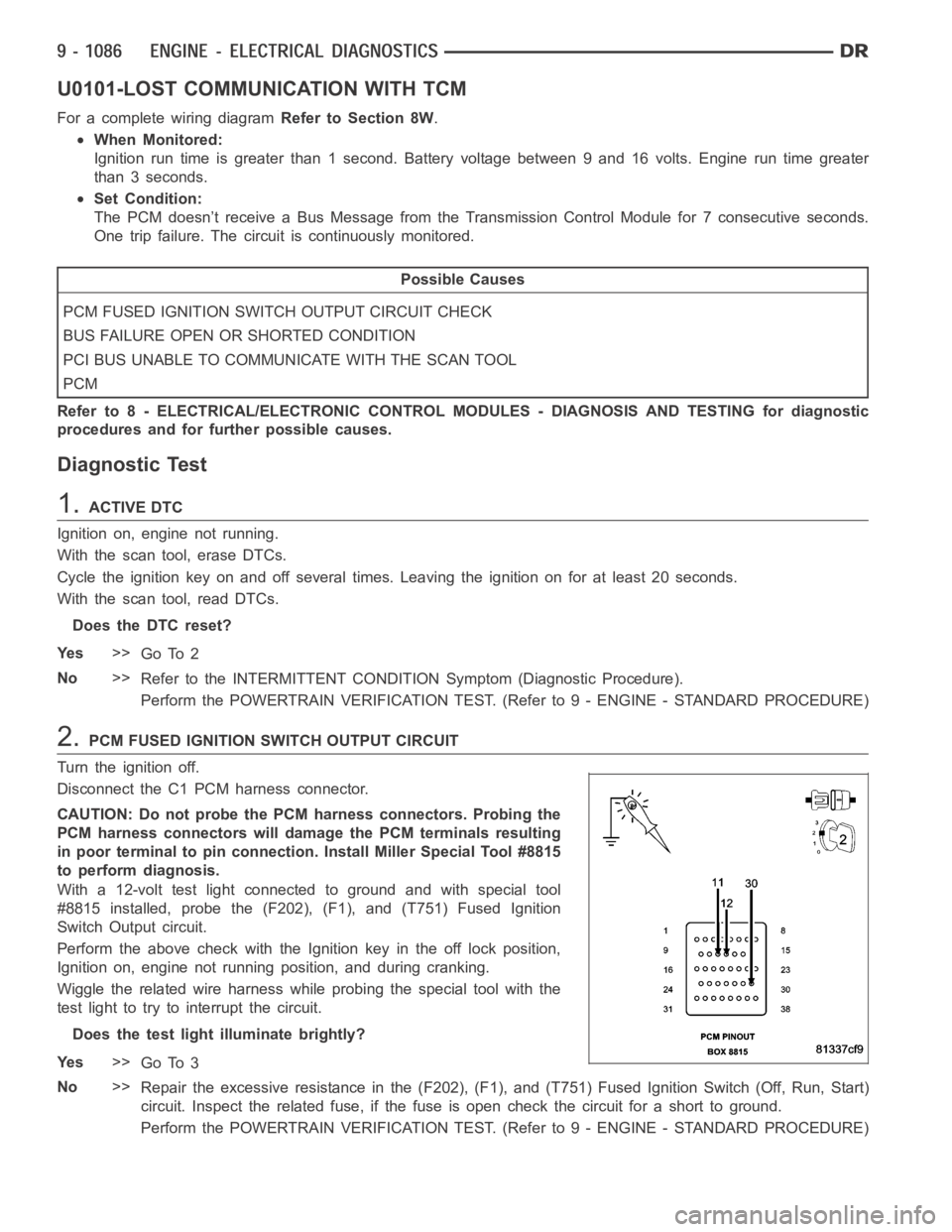
CAUTION: Do not probe the PCM harness connectors. Probing the
PCM harness connectors will damage the PCM terminals resulting
in poor terminal to pin connection. Install Miller Special Tool #8815
to perform diagnosis.
With a 12-volt test light connected to ground and with special tool
#8815 installed, probe the (F202), (F1), and (T751) Fused Ignition
Switch Output circuit.
Perform the above check with the Ignition key in the off lock position,
Ignition on, engine not running position, and during cranking.
Wiggle the related wire harness while probing the special tool with the
test light to try to interrupt the circuit.
Does the test light illuminate brightly?
Ye s>>
Go To 3
No>>
Repair the excessive resistance in the (F202), (F1), and (T751) Fused Ignition Switch (Off, Run, Start)
circuit. Inspect the related fuse, if the fuse is open check the circuit fora short to ground.
Perform the POWERTRAIN VERIFICATION TEST. (Refer to 9 - ENGINE - STANDARD PROCEDURE)
Page 415 of 5267
When Monitored:
Ignition on.
Set Condition:
The fuel volume message the PCM is receiving is implausible. The circuit iscontinuously monitored. One Trip
fault.
Possible Causes
CAN B OPEN OR SHORTED
CLUSTER MODULE
TOTALLY INTEGRATED POWER MODULE
PCM
Always perform the Pre-Diagnostic Troubleshooting procedure before proceeding. (Refer to 9 - ENGINE -
DIAGNOSIS AND TESTING).
Theory of Operation
The Totally Integrated Power Module isn’t receiving a fuel volume signal over CAN B from the Cluster Module. The
TIPM has to send the PCM a fuel volume signal over CAN C. The signal the TIPM sendsoverCANCisimplau-
sible.
Diagnostic Test
1.ACTIVE DTC
Ignition on, engine not running.
With a scan tool read DTCs.
Is the DTC active at this time?
Ye s>>
Go To 2
No>>
Refer to the INTERMITTENT CONDITION Diagnostic Procedure.
Perform the POWERTRAIN VERIFICATION TEST. (Refer to 9 - ENGINE - STANDARD PROCEDURE)
2.CAN B BUS HARDWARE DTCS ALSO ACTIVE
With a scan tool check for DTCs in the TIPM.
Are any CAN B Hardware related DTCs active at this time?
Ye s>>
(Refer to 8 - ELECTRICAL/ELECTRONIC CONTROL MODULES - DIAGNOSIS AND TESTING) for the
appropriate diagnostic procedures.
Perform BODY VERIFICATION TEST – VER 1.
No>>
Replace and program the Powertrain Control Module per Service Information.
Perform the POWERTRAIN VERIFICATION TEST. (Refer to 9 - ENGINE - STANDARD PROCEDURE)