2006 DODGE RAM SRT-10 check engine
[x] Cancel search: check enginePage 5046 of 5267
*HVAC SYSTEM TEST
For a complete wiring diagramRefer to Section 8W.
Theory of Operation
The HVAC System Test provides a starting point in the diagnostic process byidentifying the appropriate diagnostic
procedure or system test to perform when diagnosing a given symptom, condition, or DTC. It also provides a means
for testing the entire HVAC system byutilizing the A/C-heater control’s On-Board System Tests. The On-Board Sys-
tem Tests can also assist in diagnosing stored DTCs. (Refer to 24 - HEATING &AIR CONDITIONING - DIAGNOSIS
AND TESTING) for additional information about on-board diagnostics.
Diagnostic Test
1.HVAC SYSTEM TEST
NOTE: Diagnose and repair all active DTCs before diagnosing and repairingstored DTCs.
Make a selection based on the symptom, condition, or DTC that you want to diagnose.
For Any Active DTC
Refer to the Table of Contents in this Section for a complete list of HVAC related symptoms.
Scan Tool Indicates HVAC Not Active On Bus
(Refer to 8 - ELECTRICAL/ELECTRONIC CONTROL MODULES - DIAGNOSIS AND TESTING) for no
response related diagnostic procedures.
Blower Motor Inoperative
Refer to *Blower Motor Inoperative in this Section.
Complete HVAC System Test
Go To 2
A/C System Performance Test
Go To 2
Mode Switch & Door Actuator Ckt Test
Go To 3
Actuator DTC Detection Test
Go To 4
Actuator Calibration Test
Go To 5
2.A/C SYSTEM PERFORMANCE TEST
NOTE: The following are prerequisites of the Cooldown Test. Verify each ofthe following before running the
test:
If active, diagnose and repair Evaporator Temperature Sensor related DTCs before proceeding. Refer to
the Table of Contents in this Section for a complete list of HVAC related symptoms.
Verify that the refrigerant system has an adequate charge. Check and repair as necessary before pro-
ceeding. (Refer to 24 - HEATING & AIR CONDITIONING/PLUMBING - DIAGNOSIS ANDTESTING).
Verify that the blower motor operates correctly in all speeds. Diagnose and repair all blower related faults
before proceeding.
Verify that the work area ambient temperature is above 15.6°C (60°F) before proceeding. Move the vehicle
to a warmer work area if necessary.
Verify that the evaporator temperature is above 13°C (55°F) before proceeding.
Verify that the Mode Select control is set to the panel position.
Verify that the A/C compressor is not running. If the compressor is running, turn the A/C off and allow the
evaporator to warm up before proceeding.
NOTE: Running the AC Cooldown test will cause the A/C status indicator to flash.
NOTE: One or more status messages will display on the scan tool after running the Cooldown Test. These
messages will clear after paging back out of this test function. Therefore, it is important to note all mes-
sages before doing so.
Start the engine.
Turn the Blower control to the high speed position.
Page 5056 of 5267
Condition Possible Causes Correction
5. Engine overheating.5. Refer to Cooling for more information. Test the
cooling system and repair, if required.
The low side pressure is too
high, and the high side
pressure is too low.1. Accessory drive belt
slipping.1. Refer to Cooling for more information. Inspect
the accessory drive belt condition and tension.
Tighten or replace the accessory drive belt, if
required.
2. Fixed orifice tube not
installed.2. See A/C Orifice Tube in this group. Replace the
liquid line, if required.
3. Faulty A/C compressor.3. See A/C Compressor in this group. Replace the
compressor, if required.
The low side pressure is too
low, and the high side
pressure is too high.1. Restricted refrigerant flow
through the refrigerant lines.1. See Liquid, Suction, and Discharge Line in this
group. Inspect the refrigerant lines for kinks, tight
bends or improper routing. Correct the routing or
replace the refrigerant line, if required.
2. Restricted refrigerant flow
through the fixed orifice
tube.2. See A/C Orifice Tube in this group. Replace the
liquid line, if required.
3. Restricted refrigerant flow
through the condenser.3. See A/C Condenser in this group. Replace the
restricted condenser, if required.
HEATER PERFORMANCE
Before performing the following tests, refer to Group 7 - Cooling for the procedures to check the engine coolant
level and flow, engine coolant reserve/recovery system operation, accessory drive belt condition and tension, radi-
ator air flow and the fan drive operation. Perform the HVAC System Test (refer to 24 - HVAC Electrical Diagnostics).
If any diagnostic trouble codes (DTCs) are found in the A/C-heater control, powertrain control module (PCM) or
engine control module (ECM) (depending on engine application), gateway module or totally integrated power module
(TIPM), repair as necessary.
MAXIMUM HEATER OUTPUT: TEST AND ACTION
Engine coolant is provided to the heater system through two heater hoses. With the engine idling at normal oper-
ating temperature, set the temperature control to maximum heat position,the mode control to the floor position, and
the blower motor control to the highest speed position. Using a test thermometer, check the temperature of the air
being discharged from the floor outlets. Compare the test thermometer reading to the Heater Temperature Refer-
ence chart.
HEATER TEMPERATURE REFERENCE
Ambient Air Temperature16° C
(60° F)21° C
(70° F)26° C
(80° F)32° C
(90° F)
Minimum Air Temperature at
Floor Outlet62° C
(144° F)64° C
(147° F)65° C
(150° F)67° C
(153° F)
If the heater outlet air temperature is below the minimum specification, refer to Group 7 - Cooling. Both of the heater
hoses should be hot to the touch. The coolant return heater hose should be slightly cooler than the coolant supply
heater hose. If the return hose is much cooler than the supply hose, locate and repair the engine coolant flow
obstruction in the cooling system. RefertoGroup7-Coolingformoreinformation.
OBSTRUCTED COOLANT FLOW
Possible locations or causes of obstructed coolant flow are as follows:
Faulty water pump.
Faulty thermostat.
Pinched or kinked heater hoses.
Page 5073 of 5267
CLUTCH-A/C COMPRESSOR
DESCRIPTION
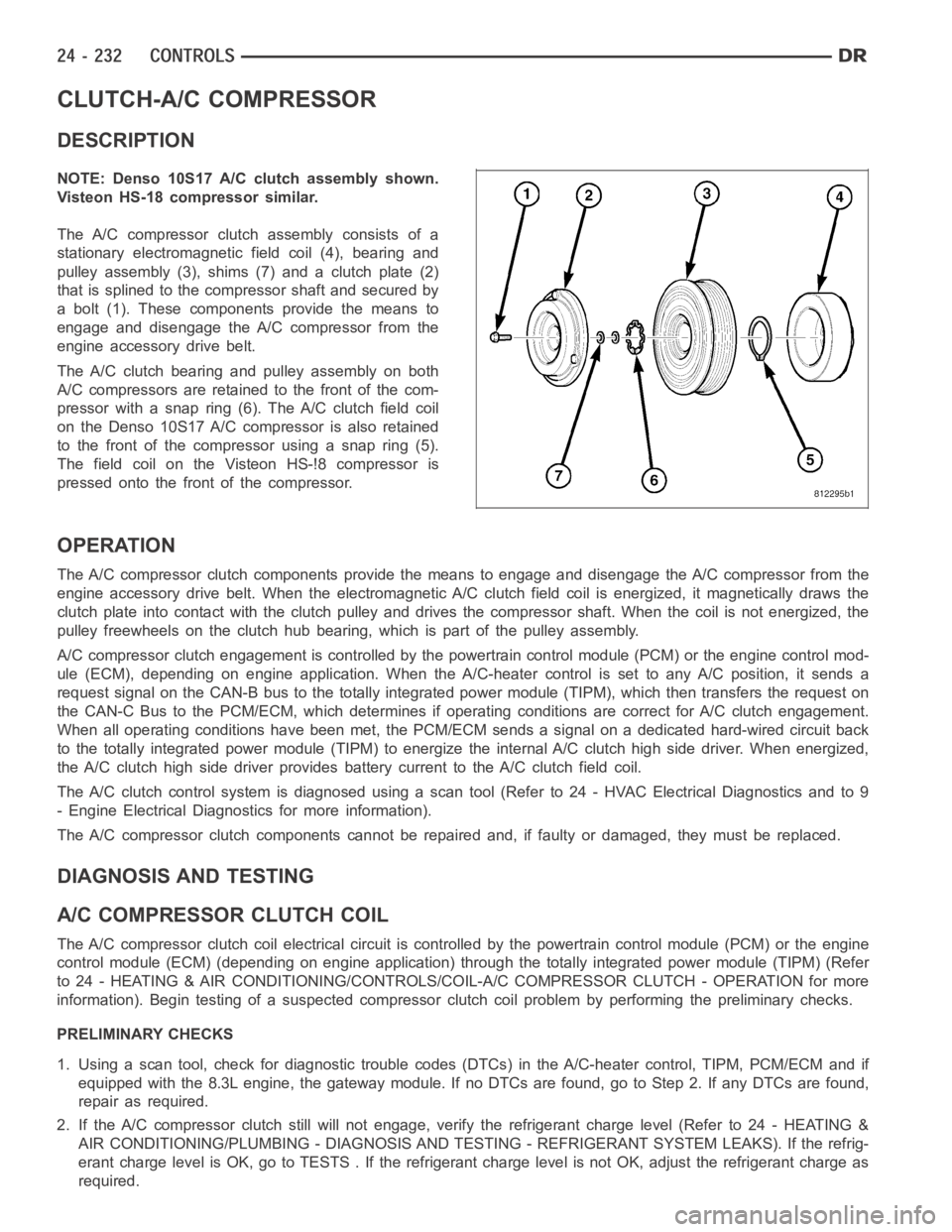
NOTE: Denso 10S17 A/C clutch assembly shown.
Visteon HS-18 compressor similar.
The A/C compressor clutch assembly consists of a
stationary electromagnetic field coil (4), bearing and
pulley assembly (3), shims (7) and a clutch plate (2)
that is splined to the compressor shaft and secured by
a bolt (1). These components provide the means to
engage and disengage the A/C compressor from the
engine accessory drive belt.
The A/C clutch bearing and pulley assembly on both
A/C compressors are retained to the front of the com-
pressor with a snap ring (6). The A/C clutch field coil
on the Denso 10S17 A/C compressor is also retained
to the front of the compressor using a snap ring (5).
The field coil on the Visteon HS-!8 compressor is
pressed onto the front of the compressor.
OPERATION
The A/C compressor clutch components provide the means to engage and disengage the A/C compressor from the
engine accessory drive belt. When the electromagnetic A/C clutch field coil is energized, it magnetically draws the
clutch plate into contact with the clutch pulley and drives the compressorshaft. When the coil is not energized, the
pulley freewheels on the clutch hub bearing, which is part of the pulley assembly.
A/C compressor clutch engagement is controlled by the powertrain controlmodule (PCM) or the engine control mod-
ule (ECM), depending on engine application. When the A/C-heater control is set to any A/C position, it sends a
request signal on the CAN-B bus to the totally integrated power module (TIPM), which then transfers the request on
the CAN-C Bus to the PCM/ECM, which determines if operating conditions arecorrect for A/C clutch engagement.
When all operating conditions have been met, the PCM/ECM sends a signal on adedicated hard-wired circuit back
to the totally integrated power module (TIPM) to energize the internal A/Cclutch high side driver. When energized,
the A/C clutch high side driver provides battery current to the A/C clutch field coil.
The A/C clutch control system is diagnosed using a scan tool (Refer to 24 - HVAC Electrical Diagnostics and to 9
- Engine Electrical Diagnostics for more information).
The A/C compressor clutch components cannot be repaired and, if faulty or damaged, they must be replaced.
DIAGNOSIS AND TESTING
A/CCOMPRESSORCLUTCHCOIL
The A/C compressor clutch coil electrical circuit is controlled by the powertrain control module (PCM) or the engine
control module (ECM) (depending on engine application) through the totally integrated power module (TIPM) (Refer
to 24 - HEATING & AIR CONDITIONING/CONTROLS/COIL-A/C COMPRESSOR CLUTCH -OPERATION for more
information). Begin testing of a suspected compressor clutch coil problem by performing the preliminary checks.
PRELIMINARY CHECKS
1. Using a scan tool, check for diagnostic trouble codes (DTCs) in the A/C-heater control, TIPM, PCM/ECM and if
equipped with the 8.3L engine, the gateway module. If no DTCs are found, go to Step 2. If any DTCs are found,
repair as required.
2. If the A/C compressor clutch still will not engage, verify the refrigerant charge level (Refer to 24 - HEATING &
AIR CONDITIONING/PLUMBING - DIAGNOSIS AND TESTING - REFRIGERANT SYSTEM LEAKS). If the refrig-
erant charge level is OK, go to TESTS . If the refrigerant charge level is notOK, adjust the refrigerant charge as
required.
Page 5074 of 5267
TESTS
1. Verify the battery state of charge (Refer to 8 - ELECTRICAL/BATTERY SYSTEM/BATTERY - DIAGNOSIS AND
TESTING).
2. Connect an ammeter (0 to 10 ampere scale selected) in series with the clutch coil feed terminal. Connect a
voltmeter (0 to 20 volt scale selected) to measure voltage across the battery and the clutch coil.
3. With the A/C-heater control in the A/C mode and the blower motor at low speed, start the engine and allow it to
run at a normal idle speed.
4. The A/C compressor clutch should engage immediately, and the clutch coil supply voltage should be within two
volts of the battery voltage. If the coil supply voltage is OK, go to Step 5. If the coil supply voltage is not within
two volts of battery voltage, test the clutch coil feed circuit for excessive voltage drop and repair as necessary.
5. For the acceptable A/C clutch coil current draw specifications refer to24 - HEATING & AIR CONDITIONING -
SPECIFICATIONS. Specifications apply for a work area temperature of 21° C(70° F). If voltage is more than
12.5 volts, add electrical loads by turning on electrical accessories until voltage reads below 12.5 volts.
STANDARD PROCEDURE
A/C CLUTCH PLATE INSPECTION
NOTE: The A/C clutch can be serviced inthe vehicle. The refrigerant systemcan remain fully-charged dur-
ing compressor clutch, pulley and bearing assembly, or coil replacement.
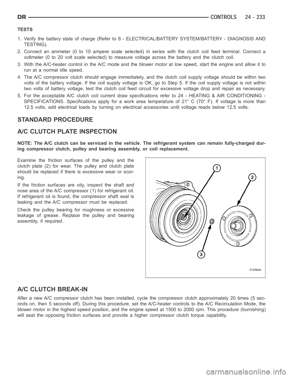
Examine the friction surfaces of the pulley and the
clutch plate (2) for wear. The pulley and clutch plate
should be replaced if there is excessive wear or scor-
ing.
If the friction surfaces are oily, inspect the shaft and
nose area of the A/C compressor (1) for refrigerant oil.
If refrigerant oil is found, the compressor shaft seal is
leaking and the A/C compressor must be replaced.
Check the pulley bearing for roughness or excessive
leakage of grease. Replace the pulley and bearing
assembly, if required.
A/C CLUTCH BREAK-IN
After a new A/C compressor clutch hasbeen installed, cycle the compressorclutch approximately 20 times (5 sec-
onds on, then 5 seconds off). During this procedure, set the A/C-heater controls to the A/C Recirculation Mode, the
blower motor in the highest speed position, and the engine speed at 1500 to 2000 rpm. This procedure (burnishing)
will seat the opposing friction surfaces and provide a higher compressor clutch torque capability.
Page 5081 of 5267
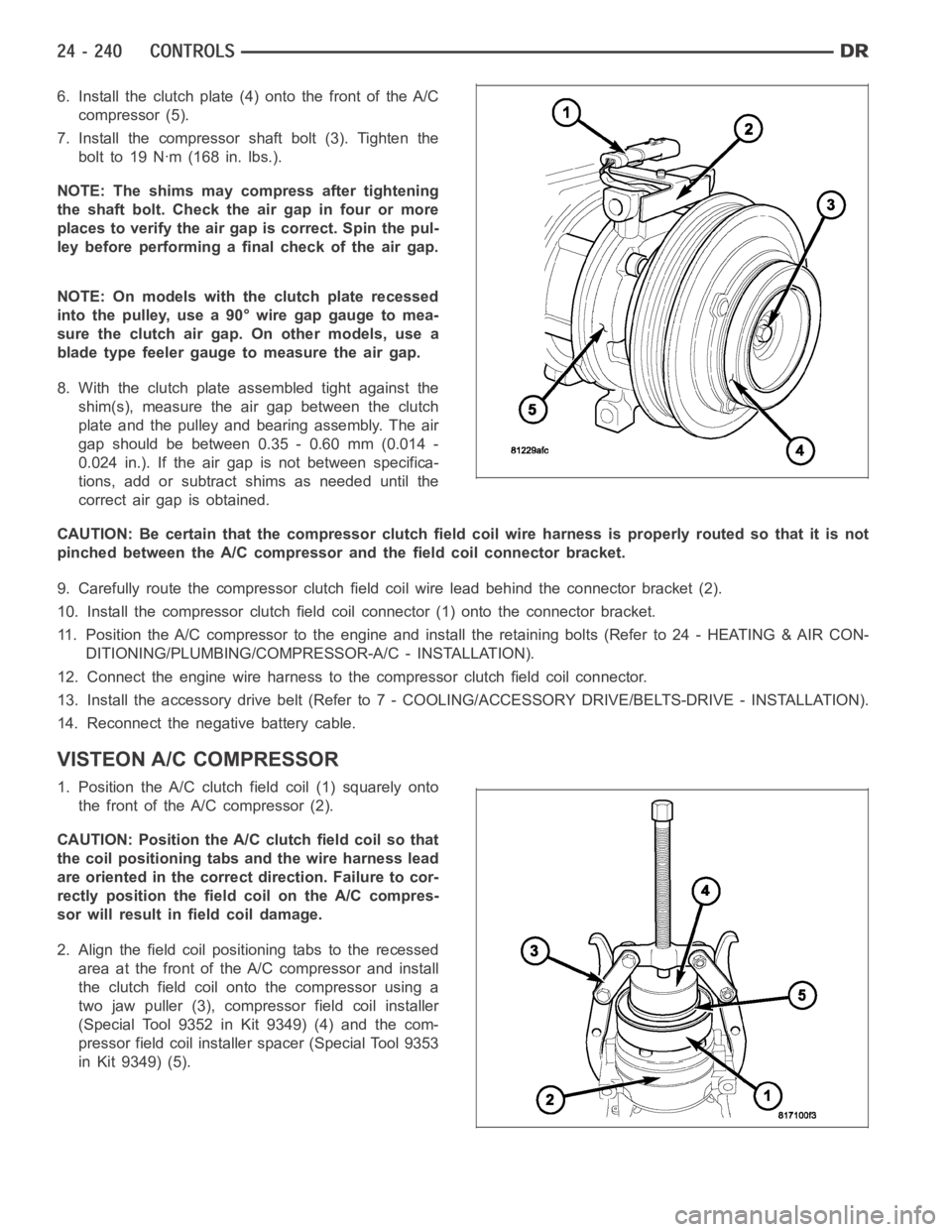
6. Install the clutch plate (4) onto the front of the A/C
compressor (5).
7. Install the compressor shaft bolt (3). Tighten the
bolt to 19 Nꞏm (168 in. lbs.).
NOTE: The shims may compress after tightening
the shaft bolt. Check the air gap in four or more
places to verify the air gap is correct. Spin the pul-
ley before performing a final check of the air gap.
NOTE: On models with the clutch plate recessed
intothepulley,usea90°wiregapgaugetomea-
sure the clutch air gap. On other models, use a
blade type feeler gauge to measure the air gap.
8. With the clutch plate assembled tight against the
shim(s), measure the air gap between the clutch
plate and the pulley and bearing assembly. The air
gap should be between 0.35 - 0.60 mm (0.014 -
0.024 in.). If the air gap is not between specifica-
tions, add or subtract shims as needed until the
correct air gap is obtained.
CAUTION: Be certain that the compressor clutch field coil wire harness is properly routed so that it is not
pinched between the A/C compressor and the field coil connector bracket.
9. Carefully route the compressor clutch field coil wire lead behind the connector bracket (2).
10. Install the compressor clutch fieldcoil connector (1) onto the connector bracket.
11. Position the A/C compressor to the engine and install the retaining bolts (Refer to 24 - HEATING & AIR CON-
DITIONING/PLUMBING/COMPRESSOR-A/C - INSTALLATION).
12. Connect the engine wire harness to the compressor clutch field coil connector.
13. Install the accessory drive belt (Refer to 7 - COOLING/ACCESSORY DRIVE/BELTS-DRIVE - INSTALLATION).
14. Reconnect the negative battery cable.
VISTEON A/C COMPRESSOR
1. Position the A/C clutch field coil (1) squarely onto
the front of the A/C compressor (2).
CAUTION: Position the A/C clutch field coil so that
the coil positioning tabs and the wire harness lead
are oriented in the correct direction. Failure to cor-
rectly position the fieldcoil on the A/C compres-
sor will result in field coil damage.
2. Align the field coil positioning tabs to the recessed
area at the front of the A/C compressor and install
the clutch field coil onto the compressor using a
two jaw puller (3), compressor field coil installer
(Special Tool 9352 in Kit 9349) (4) and the com-
pressor field coil installer spacer (Special Tool 9353
in Kit 9349) (5).
Page 5083 of 5267
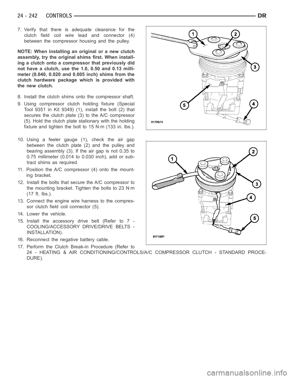
7. Verify that there is adequate clearance for the
clutch field coil wire lead and connector (4)
between the compressor housing and the pulley.
NOTE: When installing an original or a new clutch
assembly, try the original shims first. When install-
ing a clutch onto a compressor that previously did
not have a clutch, use the 1.0, 0.50 and 0.13 milli-
meter (0.040, 0.020 and 0.005 inch) shims from the
clutch hardware package which is provided with
the new clutch.
8. Install the clutch shims onto the compressor shaft.
9. Using compressor clutch holding fixture (Special
Tool 9351 in Kit 9349) (1), install the bolt (2) that
secures the clutch plate (3) to the A/C compressor
(5). Hold the clutch plate stationary with the holding
fixture and tighten the bolt to 15 Nꞏm (133 in. lbs.).
10. Using a feeler gauge (1), check the air gap
between the clutch plate (2) and the pulley and
bearing assembly (3). If the air gap is not 0.35 to
0.75 millimeter (0.014 to 0.030 inch), add or sub-
tract shims as required.
11. Position the A/C compressor (4) onto the mount-
ing bracket.
12. Install the bolts that secure the A/C compressor to
themountingbracket.Tightentheboltsto23Nꞏm
(17 ft. lbs.).
13. Connect the engine wire harness to the compres-
sor clutch field coil connector (5).
14. Lower the vehicle.
15. Install the accessory drive belt (Refer to 7 -
COOLING/ACCESSORY DRIVE/DRIVE BELTS -
INSTALLATION).
16. Reconnect the negative battery cable.
17. Perform the Clutch Break-in Procedure (Refer to
24 - HEATING & AIR CONDITIONING/CONTROLS/A/C COMPRESSOR CLUTCH - STANDARD PROCE-
DURE).
Page 5137 of 5267
DIAGNOSIS AND TESTING
A/C COMPRESSOR
When investigating an A/C system related noise, you must first know the conditions under which the noise occurs.
These conditions include: weather, vehicle speed, transmission in gear or neutral, engine speed, engine tempera-
ture, and any other special conditions. Noises that develop during A/C operation can often be misleading. For exam-
ple: What sounds like a failed front engine bearing or connecting rod, may be caused by loose bolts, nuts, mounting
brackets or a loose compressor clutch assembly.
Drive belts are speed sensitive. At different engine speeds and dependingupon drive belt tension, drive belts can
develop noises that are mistaken for an A/C compressor noise. Improper drive belt tension can cause a misleading
noise when the compressor clutch is engaged, which may not occur when the compressor clutch is disengaged.
Check the accessory drive belt condition and tension as described in Cooling before beginning this procedure.
1. Select a quiet area for testing. Duplicate the complaint conditions as much as possible. Turn the A/C compressor
On and Off several times to clearly identify the compressor noise. Listen to the A/C compressor while the clutch
is engaged and disengaged. Probe the A/C compressor with an engine stethoscope or a long screwdriver with
the handle held to your ear to better localize the source of the noise.
2. Loosen all of the compressor mounting hardware and retighten. Check thecompressor clutch retainer. Be certain
that the clutch field coil is mounted securely to the A/C compressor, and that the clutch plate and pulley are
properly aligned and have the correct air gap (Refer to 24 - HEATING & AIR CONDITIONING/CONTROLS/
CLUTCH-A/C COMPRESSOR - INSTALLATION).
3. To duplicate high-ambient temperature conditions (high head pressure), restrict the air flow through the A/C con-
denser. Install a manifold gauge set or a scan tool to be certain that the discharge pressure does not exceed
2760 kPa (400 psi).
4. Check the refrigerant system plumbing for incorrect routing, rubbing or interference, which can cause unusual
noises. Also check the refrigerant lines and hoses for kinks or sharp bendsthat will restrict refrigerant flow, which
can cause noises (Refer to 24 - HEATING & AIR CONDITIONING/PLUMBING - DESCRIPTION - REFRIGER-
ANT LINES).
5. If the noise is from opening and closing of the high pressure relief valve, recover, evacuate and recharge the
refrigerant system (Refer to 24 - HEATING & AIR CONDITIONING/PLUMBING - STANDARD PROCEDURE -
REFRIGERANT SYSTEM RECOVERY), (Refer to 24 - HEATING & AIR CONDITIONING/PLUMBING - STAN-
DARD PROCEDURE - REFRIGERANT SYSTEM EVACUATE) and (Refer to 24 - HEATING & AIR CONDITION-
ING/PLUMBING - STANDARD PROCEDURE - REFRIGERANT SYSTEM CHARGE). If the high pressure relief
valve still does not seat properly, replace the A/C compressor (Refer to 24- HEATING & AIR CONDITIONING/
PLUMBING/COMPRESSOR-A/C - REMOVAL).
6. If the noise is from liquid refrigerant slugging in the A/C suction line,replace the A/C accumulator (Refer to 24 -
HEATING & AIR CONDITIONING/PLUMBING/ACCUMULATOR-A/C - REMOVAL) and check the refrigerant oil
level and the refrigerant system charge (Refer to 24 - HEATING & AIR CONDITIONING/PLUMBING/REFRIG-
ERANT OIL - STANDARD PROCEDURE - REFRIGERANT OIL LEVEL) (Refer to 24 - HEATING & AIR CON-
DITIONING/PLUMBING- STANDARD PROCEDURE - REFRIGERANT SYSTEM CHARGE).
7. If a slugging condition still exists after replacing the A/C accumulator, then replace the A/C compressor (Refer to
24 - HEATING & AIR CONDITIONING/PLUMBING/COMPRESSOR-A/C - REMOVAL) and repeat Step 1.
REMOVAL
3.7L/4.7L ENGINES
WARNING: Refer to the applicable warnings and cautions for this system before performing the following
operation (Refer to 24 - HEATING & AIR CONDITIONING/PLUMBING - WARNINGS) and (Refer to 24 - HEAT-
ING & AIR CONDITIONING/PLUMBING - CAUTIONS). Failure to follow the warnings and cautions could result
in possible personal injury or death.
NOTE: The A/C compressor may be removed and repositioned without disconnecting the refrigerant lines or
discharging the refrigerant system. Discharging is not necessary if servicing the compressor clutch, clutch
coil, engine, engine cylinder head or the generator.
Page 5141 of 5267
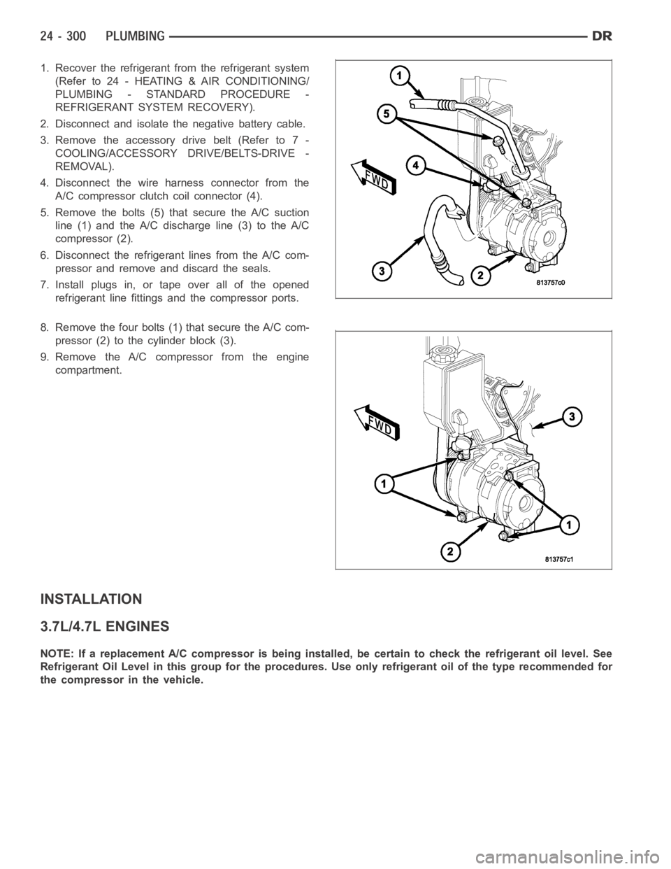
1. Recover the refrigerant from the refrigerant system
(Refer to 24 - HEATING & AIR CONDITIONING/
PLUMBING - STANDARD PROCEDURE -
REFRIGERANT SYSTEM RECOVERY).
2. Disconnect and isolate the negative battery cable.
3. Remove the accessory drive belt (Refer to 7 -
COOLING/ACCESSORY DRIVE/BELTS-DRIVE -
REMOVAL).
4. Disconnect the wire harness connector from the
A/C compressor clutch coil connector (4).
5. Remove the bolts (5) that secure the A/C suction
line (1) and the A/C discharge line (3) to the A/C
compressor (2).
6. Disconnect the refrigerant lines from the A/C com-
pressor and remove and discard the seals.
7. Install plugs in, or tape over all of the opened
refrigerant line fittings and the compressor ports.
8. Remove the four bolts (1) that secure the A/C com-
pressor (2) to the cylinder block (3).
9. Remove the A/C compressor from the engine
compartment.
INSTALLATION
3.7L/4.7L ENGINES
NOTE: If a replacement A/C compressor is being installed, be certain to check the refrigerant oil level. See
Refrigerant Oil Level in this group for the procedures. Use only refrigerant oil of the type recommended for
the compressor in the vehicle.