Page 4323 of 5267
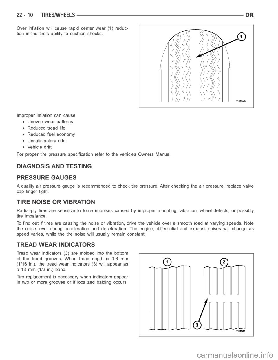
Over inflation will cause rapid center wear (1) reduc-
tion in the tire’s ability to cushion shocks.
Improper inflation can cause:
Uneven wear patterns
Reduced tread life
Reduced fuel economy
Unsatisfactory ride
Vehicle drift
For proper tire pressure specification refer to the vehicles Owners Manual.
DIAGNOSIS AND TESTING
PRESSURE GAUGES
A quality air pressure gauge is recommended to check tire pressure. After checking the air pressure, replace valve
cap finger tight.
TIRE NOISE OR VIBRATION
Radial-ply tires are sensitive to force impulses caused by improper mounting, vibration, wheel defects, or possibly
tire imbalance.
To find out if tires are causing the noise or vibration, drive the vehicle over a smooth road at varying speeds. Note
the noise level during acceleration and deceleration. The engine, differential and exhaust noises will change as
speed varies, while the tire noise will usually remain constant.
TREAD WEAR INDICATORS
Tread wear indicators (3) are molded into the bottom
of the tread grooves. When tread depth is 1.6 mm
(1/16 in.), the tread wear indicators (3) will appear as
a 13 mm (1/2 in.) band.
Tire replacement is necessary when indicators appear
in two or more grooves or if localized balding occurs.
Page 4877 of 5267
3.CHECK FOR A SHORTED CONDENSER FAN MOTOR
Reconnect the TIPM C8 harness connector.
Ignition on, engine not running.
With the scan tool, actuate the Condenser Fan.
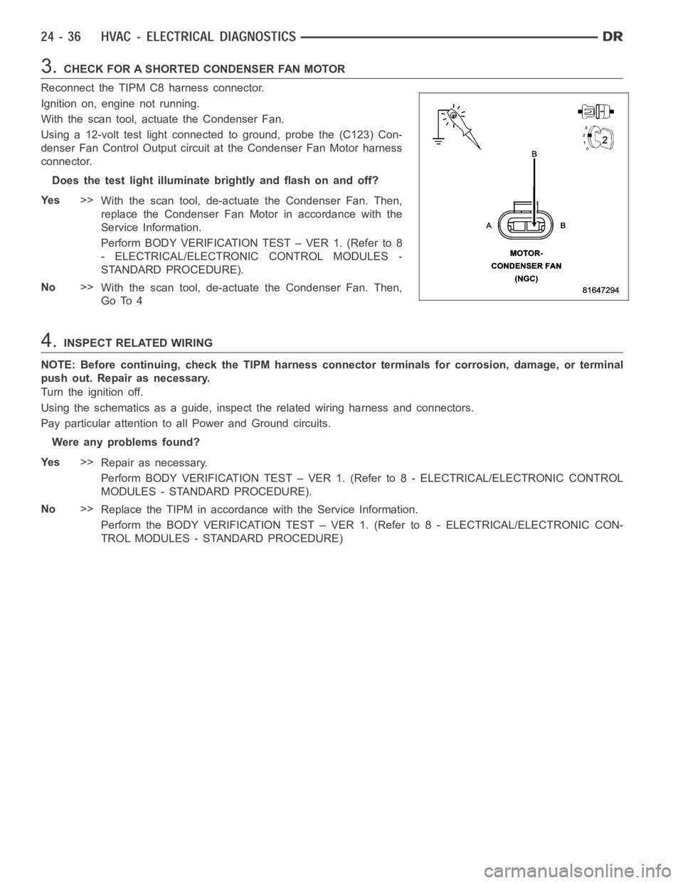
Using a 12-volt test light connected to ground, probe the (C123) Con-
denser Fan Control Output circuit at the Condenser Fan Motor harness
connector.
Does the test light illuminate brightly and flash on and off?
Ye s>>
With the scan tool, de-actuate the Condenser Fan. Then,
replace the Condenser Fan Motor in accordance with the
Service Information.
Perform BODY VERIFICATION TEST – VER 1. (Refer to 8
- ELECTRICAL/ELECTRONIC CONTROL MODULES -
STANDARD PROCEDURE).
No>>
With the scan tool, de-actuate the Condenser Fan. Then,
Go To 4
4.INSPECT RELATED WIRING
NOTE: Before continuing, check the TIPM harness connector terminals for corrosion, damage, or terminal
push out. Repair as necessary.
Turn the ignition off.
Using the schematics as a guide, inspect the related wiring harness and connectors.
Pay particular attention to all Power and Ground circuits.
Were any problems found?
Ye s>>
Repair as necessary.
Perform BODY VERIFICATION TEST – VER 1. (Refer to 8 - ELECTRICAL/ELECTRONIC CONTROL
MODULES - STANDARD PROCEDURE).
No>>
Replace the TIPM in accordance with the Service Information.
Perform the BODY VERIFICATION TEST – VER 1. (Refer to 8 - ELECTRICAL/ELECTRONIC CON-
TROL MODULES - STANDARD PROCEDURE)
Page 4879 of 5267
When Monitored:
With the ignition on. Battery voltage greater than 10.4 volts.
Set Condition:
If the Totally Integrated Power Module (TIPM) detects a shorted high condition in the (C123) Condenser Fan
Control circuit.
Possible Causes
(C123) CONDENSER FAN CONTROL OUTPUT CIRCUIT SHORTED TO BATTERY VOLTAGE
EXCESSIVE RESISTANCE IN THE (Z823) GROUND CIRCUIT
CONDENSER FAN MOTOR
TIPM
Diagnostic Test
1.VERIFY DTC IS ACTIVE
Turn the ignition on.
With the scan tool, erase TIPM DTCs.
Turn the ignition off, wait 10 seconds, and turn the ignition on.
With the scan tool, actuate the Condenser Fan.
With the scan tool, read TIPM DTCs.
Does this DTC reset?
Ye s>>
With the scan tool, de-actuate the Condenser Fan. Then, Go To 2
No>>
With the scan tool, de-actuate the Condenser Fan. Then, check for an intermittent condition by inspect-
ing the related wiring harness for chafed, pierced, pinched, and partially broken wires. Also, inspect the
related connectors for broken, bent, corroded, and contaminated terminals.
Perform BODY VERIFICATION TEST – VER 1. (Refer to 8 - ELECTRICAL/ELECTRONIC CONTROL
MODULES - STANDARD PROCEDURE).
2.CHECK (C123) CONDENSER FAN CONTROL OUTPUT CIRCUIT FOR A SHORT TO BATTERY VOLTA G E
Turn the ignition off
Disconnect the TIPM C8 harness connector.
Disconnect the Condenser Fan Motor harness connector.
Ignition on, engine not running.
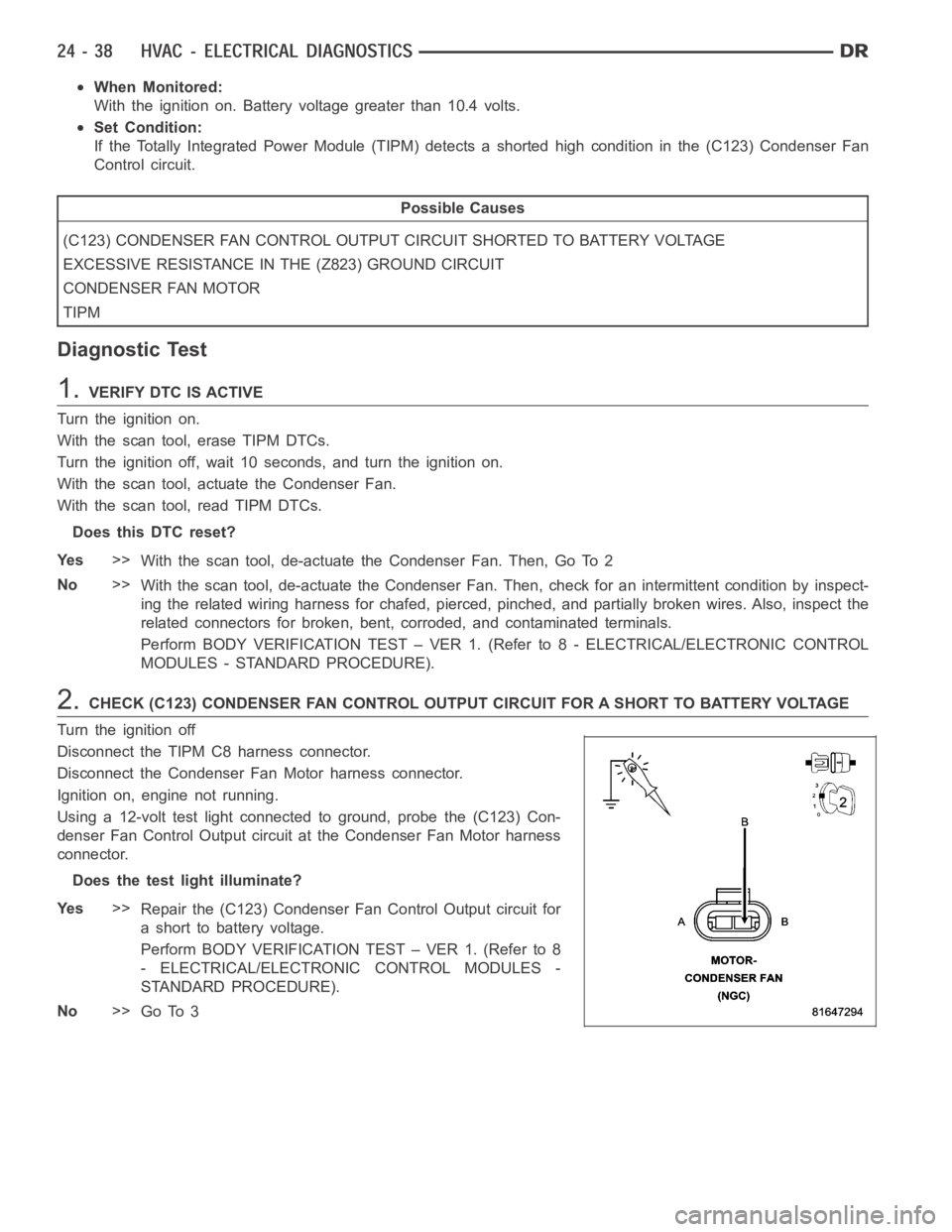
Using a 12-volt test light connected to ground, probe the (C123) Con-
denser Fan Control Output circuit at the Condenser Fan Motor harness
connector.
Does the test light illuminate?
Ye s>>
Repair the (C123) Condenser Fan Control Output circuit for
a short to battery voltage.
Perform BODY VERIFICATION TEST – VER 1. (Refer to 8
- ELECTRICAL/ELECTRONIC CONTROL MODULES -
STANDARD PROCEDURE).
No>>
Go To 3
Page 4880 of 5267
3.CHECK (Z823) GROUND CIRCUIT FOR AN OPEN
Turn the ignition off.
Reconnect the TIPM C8 harness connector.
NOTE: The test light should illuminate brightly. Compare the
brightness to that of a direct connection to the battery.
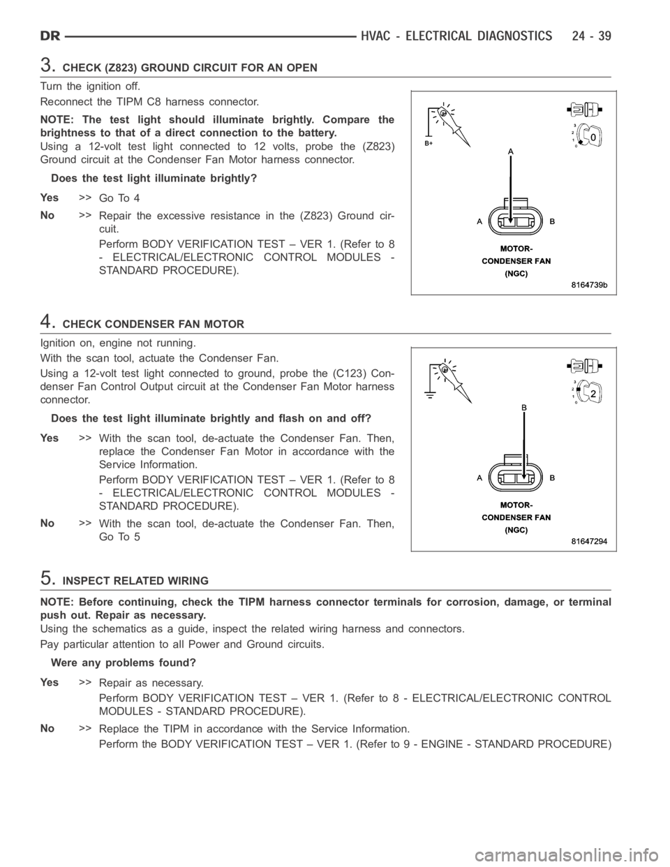
Using a 12-volt test light connected to 12 volts, probe the (Z823)
Ground circuit at the Condenser Fan Motor harness connector.
Does the test light illuminate brightly?
Ye s>>
Go To 4
No>>
Repair the excessive resistance in the (Z823) Ground cir-
cuit.
Perform BODY VERIFICATION TEST – VER 1. (Refer to 8
- ELECTRICAL/ELECTRONIC CONTROL MODULES -
STANDARD PROCEDURE).
4.CHECK CONDENSER FAN MOTOR
Ignition on, engine not running.
With the scan tool, actuate the Condenser Fan.
Using a 12-volt test light connected to ground, probe the (C123) Con-
denser Fan Control Output circuit at the Condenser Fan Motor harness
connector.
Does the test light illuminate brightly and flash on and off?
Ye s>>
With the scan tool, de-actuate the Condenser Fan. Then,
replace the Condenser Fan Motor in accordance with the
Service Information.
Perform BODY VERIFICATION TEST – VER 1. (Refer to 8
- ELECTRICAL/ELECTRONIC CONTROL MODULES -
STANDARD PROCEDURE).
No>>
With the scan tool, de-actuate the Condenser Fan. Then,
Go To 5
5.INSPECT RELATED WIRING
NOTE: Before continuing, check the TIPM harness connector terminals for corrosion, damage, or terminal
push out. Repair as necessary.
Using the schematics as a guide, inspect the related wiring harness and connectors.
Pay particular attention to all Power and Ground circuits.
Were any problems found?
Ye s>>
Repair as necessary.
Perform BODY VERIFICATION TEST – VER 1. (Refer to 8 - ELECTRICAL/ELECTRONIC CONTROL
MODULES - STANDARD PROCEDURE).
No>>
Replace the TIPM in accordance with the Service Information.
Perform the BODY VERIFICATION TEST – VER 1. (Refer to 9 - ENGINE - STANDARD PROCEDURE)
Page 4882 of 5267
2.CHECK FOR DTCs IN THE A/C HEATER CONTROL MODULE
Turn the ignition on.
With the scan tool, read HVAC DTCs.
Excluding B10B2–A/C Cool Down Test Performance, are any DTCs present in the A/C Heater Control
Module?
Ye s>>
Diagnose and Repair the DTC(s). Refer to the Table of Contents in this Section for a complete list of
HVAC related symptoms. Rerun the Cooldown Test after the repair is complete.
Perform BODY VERIFICATION TEST – VER 1. (Refer to 8 - ELECTRICAL/ELECTRONIC CONTROL
MODULES - STANDARD PROCEDURE).
No>>
Go To 3
3.CHECK FOR DTCs IN THE TIPM
With the scan tool, read TIPM DTCs.
Are any DTCs present in the TIPM?
Ye s>>
Diagnose and Repair the DTC(s). Rerun the Cooldown Test after the repair iscomplete.
Perform BODY VERIFICATION TEST – VER 1. (Refer to 8 - ELECTRICAL/ELECTRONIC CONTROL
MODULES - STANDARD PROCEDURE).
No>>
Go To 4
4.CHECK FOR DTCs IN THE PCM / ECM
With the scan tool, read PCM / ECM DTCs.
Are any DTCs present in the PCM / ECM?
Ye s>>
Diagnose and repair the DTC(s). (Refer to 9 - ENGINE - DIAGNOSIS AND TESTING) for the diagnostic
procedures. Rerun the Cooldown Test after the repair is complete.
Perform BODY VERIFICATION TEST – VER 1. (Refer to 8 - ELECTRICAL/ELECTRONIC CONTROL
MODULES - STANDARD PROCEDURE).
No>>
Refer to the Service Information for additional Cooldown Test related diagnostic information and testing
procedures. Rerun the Cooldown Test after the repair is complete.
Perform BODY VERIFICATION TEST – VER 1. (Refer to 8 - ELECTRICAL/ELECTRONIC CONTROL
MODULES - STANDARD PROCEDURE).
Page 4885 of 5267
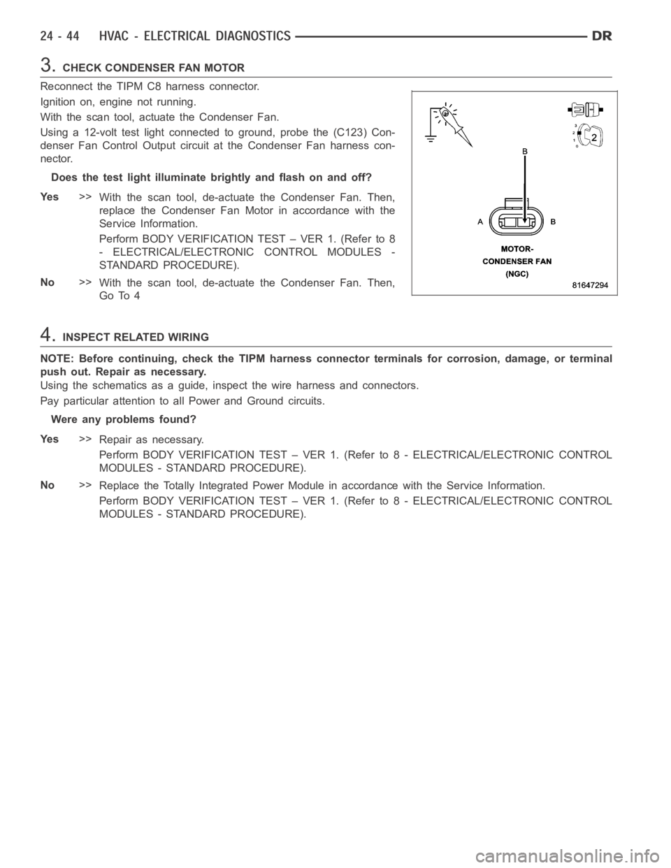
3.CHECK CONDENSER FAN MOTOR
Reconnect the TIPM C8 harness connector.
Ignition on, engine not running.
With the scan tool, actuate the Condenser Fan.
Using a 12-volt test light connected to ground, probe the (C123) Con-
denser Fan Control Output circuit at the Condenser Fan harness con-
nector.
Does the test light illuminate brightly and flash on and off?
Ye s>>
With the scan tool, de-actuate the Condenser Fan. Then,
replace the Condenser Fan Motor in accordance with the
Service Information.
Perform BODY VERIFICATION TEST – VER 1. (Refer to 8
- ELECTRICAL/ELECTRONIC CONTROL MODULES -
STANDARD PROCEDURE).
No>>
With the scan tool, de-actuate the Condenser Fan. Then,
Go To 4
4.INSPECT RELATED WIRING
NOTE: Before continuing, check the TIPM harness connector terminals for corrosion, damage, or terminal
push out. Repair as necessary.
Using the schematics as a guide, inspect the wire harness and connectors.
Pay particular attention to all Power and Ground circuits.
Were any problems found?
Ye s>>
Repair as necessary.
Perform BODY VERIFICATION TEST – VER 1. (Refer to 8 - ELECTRICAL/ELECTRONIC CONTROL
MODULES - STANDARD PROCEDURE).
No>>
Replace the Totally Integrated Power Module in accordance with the Service Information.
Perform BODY VERIFICATION TEST – VER 1. (Refer to 8 - ELECTRICAL/ELECTRONIC CONTROL
MODULES - STANDARD PROCEDURE).
Page 4894 of 5267
5.CHECK (C123) CONDENSER FAN CONTROL OUTPUT FROM TIPM
Reconnect the TIPM C8 harness connector.
Ignition on, engine not running.
With a scan tool, actuate the Condenser Fan.
Using the 12-Volt test light connected to ground, probe the (C123) Con-
denser Fan Control Output circuit in the Condenser Fan Motor harness
connector.
Does the test light illuminate brightly?
Ye s>>
With a scan tool, de-actuate the Condenser Fan. Then,
replace the Condenser Fan Motor in accordance with the
Service Information.
Perform BODY VERIFICATION TEST – VER 1. (Refer to 8
- ELECTRICAL/ELECTRONIC CONTROL MODULES -
STANDARD PROCEDURE).
No>>
With a scan tool, de-actuate the Condenser Fan. Then,
replace the TIPM in accordance with the Service Informa-
tion.
Perform BODY VERIFICATION TEST – VER 1. (Refer to 8 - ELECTRICAL/ELECTRONIC CONTROL
MODULES - STANDARD PROCEDURE).
Page 5034 of 5267
2.CHECK FOR DTCs IN THE A/C HEATER CONTROL MODULE
Turn the ignition on.
With the scan tool, read HVAC DTCs.
Excluding B1079–Climate Control Cool Down Test Excessive Time, are any DTCs present in the A/C
Heater Control Module?
Ye s>>
Diagnose and Repair the DTC(s). Refer to the Table of Contents in this Section for a complete list of
HVAC related symptoms. Rerun the Cooldown Test after the repair is complete.
Perform BODY VERIFICATION TEST – VER 1. (Refer to 8 - ELECTRICAL/ELECTRONIC CONTROL
MODULES - STANDARD PROCEDURE).
No>>
Go To 3
3.CHECK FOR DTCs IN THE TIPM
With the scan tool, read TIPM DTCs.
Are any DTCs present in the TIPM?
Ye s>>
Diagnose and Repair the DTC(s). Rerun the Cooldown Test after the repair iscomplete.
Perform BODY VERIFICATION TEST – VER 1. (Refer to 8 - ELECTRICAL/ELECTRONIC CONTROL
MODULES - STANDARD PROCEDURE).
No>>
Go To 4
4.CHECK FOR DTCs IN THE PCM / ECM
With the scan tool, read PCM / ECM DTCs.
Are any DTCs present in the PCM / ECM?
Ye s>>
Diagnose and repair the DTC(s). (Refer to 9 - ENGINE - DIAGNOSIS AND TESTING) for the diagnostic
procedures. Rerun the Cooldown Test after the repair is complete.
Perform BODY VERIFICATION TEST – VER 1. (Refer to 8 - ELECTRICAL/ELECTRONIC CONTROL
MODULES - STANDARD PROCEDURE).
No>>
Refer to the Service Information for additional Cooldown Test related diagnostic information and testing
procedures. Rerun the Cooldown Test after the repair is complete.
Perform BODY VERIFICATION TEST – VER 1. (Refer to 8 - ELECTRICAL/ELECTRONIC CONTROL
MODULES - STANDARD PROCEDURE).