2006 DODGE RAM SRT-10 check engine
[x] Cancel search: check enginePage 3947 of 5267
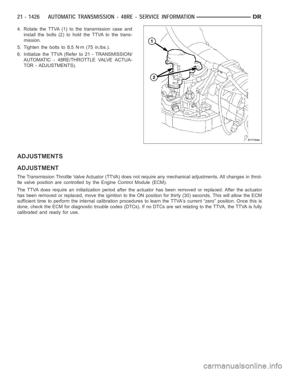
4. Rotate the TTVA (1) to the transmission case and
install the bolts (2) to hold the TTVA to the trans-
mission.
5. Tighten the bolts to 8.5 Nꞏm (75 in.lbs.).
6. Initialize the TTVA (Refer to 21 - TRANSMISSION/
AUTOMATIC - 48RE/THROTTLE VALVE ACTUA-
TOR - ADJUSTMENTS).
ADJUSTMENTS
ADJUSTMENT
The Transmission Throttle Valve Actuator (TTVA) does not require any mechanical adjustments. All changes in throt-
tle valve position are controlled by the Engine Control Module (ECM).
The TTVA does require an initialization period after the actuator has beenremoved or replaced. After the actuator
has been removed or replaced, move the iginition to the ON position for thirty (30) seconds. This will allow the ECM
sufficient time to perform the internal calibration procedures to learn the TTVA’s current “zero” position. Once this is
done, check the ECM for diagnostic trouble codes (DTCs). If no DTCs are set relating to the TTVA, the TTVA is fully
calibrated and ready for use.
Page 3959 of 5267
VALVE-TORQUE CONVERTER DRAINBACK
DESCRIPTION
GAS ENGINES
The drainback valve is located in the transmission cooler outlet (pressure) line.
DIESEL ENGINE
The converter drainback check valve is located in the in the TOC pressure - supply line, between the engine
mounted TOC and the air to oil TOC.
OPERATION
GAS ENGINES
The valve prevents fluid from draining from the converter into the cooler and lines when the vehicle is shut down for
lengthy periods. Production valves have a hose nipple at one end, while theopposite end is threaded for a flare
fitting. All valves have an arrow (or similar mark) to indicate direction of flow through the valve.
DIESEL ENGINE
The valve prevents fluid from draining from the converter into the cooler and lines when the vehicle is shut down for
lengthy periods. Production valves have pipe thread on one end, while the opposite end is threaded for a flare
fitting, and are threaded into the oil cooler mounted on the side of the engine. All valves have an arrow (or similar
mark) to indicate direction of flow through the valve.
STANDARD PROCEDURE
GAS ENGINES
The converter drainback check valve is located in the cooler outlet (pressure) line near the radiator tank. The valve
prevents fluid drainback when the vehicle is parked for lengthy periods. The valve check ball is spring loaded and
has an opening pressure of approximately 2 psi.
The valve is serviced as an assembly; it is not repairable. Do not clean the valve if restricted, or contaminated by
sludge, or debris. If the valve fails, or if a transmission malfunction occurs that generates significant amounts of
sludge and/or clutch particles and metal shavings, the valve must be replaced.
If the valve is restricted, installed backwards, or in the wrong line, it will cause an transmission overheating condition
and possible transmission failure.
CAUTION: The drainback valve is a one-way flow device. It must be properly orientedintermsofflowdirec-
tion for the cooler to function properly. The valve must be installed in thepressure line. Otherwise flow will
be blocked and would cause an transmission overheating condition and eventual transmission failure.
DIESEL ENGINE
The converter drainback check valve is located in the in the TOC pressure - supply line, between the engine
mounted transmission oil cooler and the air to oil transmission oil cooler. The valve prevents fluid drainback when
the vehicle is parked for lengthy periods. The valve check ball is spring loaded and has an opening pressure of
approximately 2 psi.
The valve is serviced as an assembly; it is not repairable. Do not clean the valve if restricted, or contaminated by
sludge, or debris. If the valve fails, or if a transmission malfunction occurs that generates significant amounts of
sludge and/or clutch particles and metal shavings, the valve must be replaced.
If the valve is restricted, installed backwards, or in the wrong line, it will cause an transmission overheating condition
and possible transmission failure.
Page 4043 of 5267
3.ACTUATE T-CASE MOTOR
Reconnect the TIPM C4 harness connector.
Ignition on, engine not running.
With the scan tool, actuate the T-Case Motor Brake.
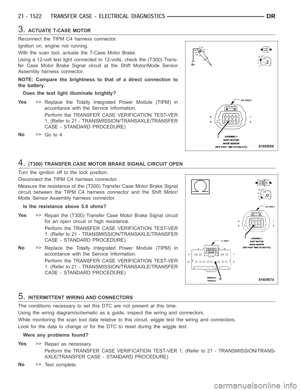
Using a 12-volt test light connected to 12-volts, check the (T300) Trans-
fer Case Motor Brake Signal circuit at the Shift Motor/Mode Sensor
Assembly harness connector.
NOTE: Compare the brightness to that of a direct connection to
the battery.
Does the test light illuminate brightly?
Ye s>>
Replace the Totally Integrated Power Module (TIPM) in
accordance with the Service Information.
Perform the TRANSFER CASE VERIFICATION TEST-VER
1. (Refer to 21 - TRANSMISSION/TRANSAXLE/TRANSFER
CASE - STANDARD PROCEDURE)
No>>
Go to 4
4.(T300) TRANSFER CASE MOTOR BRAKE SIGNAL CIRCUIT OPEN
Turn the ignition off to the lock position.
Disconnect the TIPM C4 harness connector.
Measure the resistance of the (T300) Transfer Case Motor Brake Signal
circuit between the TIPM C4 harness connector and the Shift Motor/
Mode Sensor Assembly harness connector.
Is the resistance above 5.0 ohms?
Ye s>>
Repair the (T300) Transfer Case Motor Brake Signal circuit
for an open circuit or high resistance.
Perform the TRANSFER CASE VERIFICATION TEST-VER
1. (Refer to 21 - TRANSMISSION/TRANSAXLE/TRANSFER
CASE - STANDARD PROCEDURE)
No>>
Replace the Totally Integrated Power Module (TIPM) in
accordance with the Service Information.
Perform the TRANSFER CASE VERIFICATION TEST-VER
1. (Refer to 21 - TRANSMISSION/TRANSAXLE/TRANSFER
CASE - STANDARD PROCEDURE)
5.INTERMITTENT WIRING AND CONNECTORS
The conditions necessary to set this DTC are not present at this time.
Using the wiring diagram/schematic as a guide, inspect the wiring and connectors.
While monitoring the scan tool data relative to this circuit, wiggle test the wiring and connectors.
Look for the data to change or for the DTC to reset during the wiggle test.
Were any problems found?
Ye s>>
Repair as necessary.
Perform the TRANSFER CASE VERIFICATION TEST-VER 1. (Refer to 21 - TRANSMISSION/TRANS-
AXLE/TRANSFER CASE - STANDARD PROCEDURE)
No>>
Te s t c o m p l e t e .
Page 4045 of 5267
When Monitored:
With the ignition on and no system undervoltage or overvoltage condition present.
Set Condition:
The Totally Integrated Power Module (TIPM) detects voltage on the Transfer Case Brake circuit when the out-
put is off.
Possible Causes
(T300) T-CASE MOTOR BRAKE CIRCUIT OPEN
(T300) T-CASE MOTOR BRAKE CIRCUIT SHORTED TO POWER
TRANSFER CASE MOTOR ASSEMBLY
TOTALLY INTEGRATED POWER MODULE (TIPM)
Diagnostic Test
1.CHECK IF THE DTC IS ACTIVE
Start the engine and allow it to idle.
Move the Transfer Case Selector Switch to each position several times.
With the scan tool, read the TIPM DTCs.
Is the status Active for this DTC?
Ye s>>
Go to 2
No>>
Go to 5
2.(T300) TRANSFER CASE MOTOR BRAKE SIGNAL CIRCUIT SHORTED TO VOLTAGE
Turn the ignition off to the lock position.
Disconnect the Shift Motor/Mode Sensor Assembly harness connector.
Disconnect the TIPM C4 harness connector.
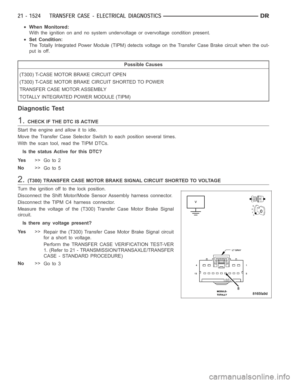
Measure the voltage of the (T300) Transfer Case Motor Brake Signal
circuit.
Is there any voltage present?
Ye s>>
Repair the (T300) Transfer Case Motor Brake Signal circuit
for a short to voltage.
Perform the TRANSFER CASE VERIFICATION TEST-VER
1. (Refer to 21 - TRANSMISSION/TRANSAXLE/TRANSFER
CASE - STANDARD PROCEDURE)
No>>
Go to 3
Page 4062 of 5267
When Monitored:
The ignition on, with the T-Case Switch in a 4W/LO position.
Set Condition:
The TIPM detects the Front Axle Lock Control circuit is shorted low.
Possible Causes
(G304) FRONT AXLE LOCK CONTROL CIRCUIT SHORTED TO GROUND
FRONT AXLE DISCONNECT (FAD) MODULE
TOTALLY INTEGRATED POWER MODULE (TIPM)
Diagnostic Test
1.ACTIVE DTC
CAUTION: Before removing the TIPM harness connectors, clean the connector and locking cam area of dirt
and debris. Failure to do so can result in the connector being jammed or damage to the locking cams on
the harness connector or module. Do not force the assist arm when releasingor installing the harness con-
nector.
Ignition on, engine not running.
With the scan tool, read the TIPM DTCs.
Is the status Active for this DTC?
Ye s>>
Go To 2
No>>
Go To 6
2.(G304) FRONT AXLE LOCK CONTROL CIRCUIT
Turn the ignition off to the lock position.
Disconnect the FAD harness connector.
Ignition on, engine not running.
With the scan tool, actuate the Front Axle Lock Control in the TIPM.
Using a 12-volt test light connected to 12-volts, check the (G304) Front Axle Lock Control circuit in the FAD harness
connector.
Does the test light illuminate brightly?
Ye s>>
Go To 5
No>>
Go To 3
Page 4070 of 5267
When Monitored:
The ignition on, with the T-Case Switch in 4W/LO position.
Set Condition:
The TIPM detects the Front Axle Lock Signal circuit is shorted low.
Possible Causes
(A880) FUSED B+ CIRCUIT OPEN
(G303) FRONT AXLE LOCK SIGNAL CIRCUIT OPEN
(G304) FRONT AXLE LOCK CONTROL CIRCUIT OPEN
FRONT AXLE DISCONNECT (FAD) MODULE
TOTALLY INTEGRATED POWER MODULE (TIPM)
Diagnostic Test
1.ACTIVE DTC
CAUTION: Before removing the TIPM harness connectors, clean the connector and locking cam area of dirt
and debris. Failure to do so can result in the connector being jammed or damage to the locking cams on
the harness connector or module. Do not force the assist arm when releasingor installing the harness con-
nector.
Ignition on, engine not running.
With the scan tool, read the TIPM DTCs.
Is the DTC currently active?
Ye s>>
Go To 2
No>>
Go To 6
2.(A880) FUSED B+ OPEN
Turn the ignition off to the lock position.
Disconnect the FAD harness connector.
Ignition on, engine not running.
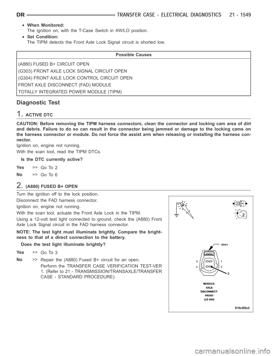
With the scan tool, actuate the Front Axle Lock in the TIPM.
Using a 12-volt test light connected to ground, check the (A880) Front
Axle Lock Signal circuit in the FAD harness connector.
NOTE: The test light must illuminate brightly. Compare the bright-
ness to that of a direct connection to the battery.
Does the test light illuminate brightly?
Ye s>>
Go To 3
No>>
Repair the (A880) Fused B+ circuit for an open.
Perform the TRANSFER CASE VERIFICATION TEST-VER
1. (Refer to 21 - TRANSMISSION/TRANSAXLE/TRANSFER
CASE - STANDARD PROCEDURE)
Page 4076 of 5267
3.(G304) FRONT AXLE LOCK CONTROL CIRCUIT
Turn the ignition off to the lock position.
Disconnect the TIPM C2 harness connector.
Ignition on, engine not running.
With the scan tool, actuate the TIPM.
Using a 12-volt test light connected to 12-volts, check the (G304) Front Axle Lock Control circuit in the FAD harness
connector.
Does the test light turn on and off?
Ye s>>
Go To 5
No>>
Go To 4
4.(G304) FRONT AXLE LOCK CONTROL CIRCUIT SHORTED TO GROUND
Turn the ignition off to the lock position.
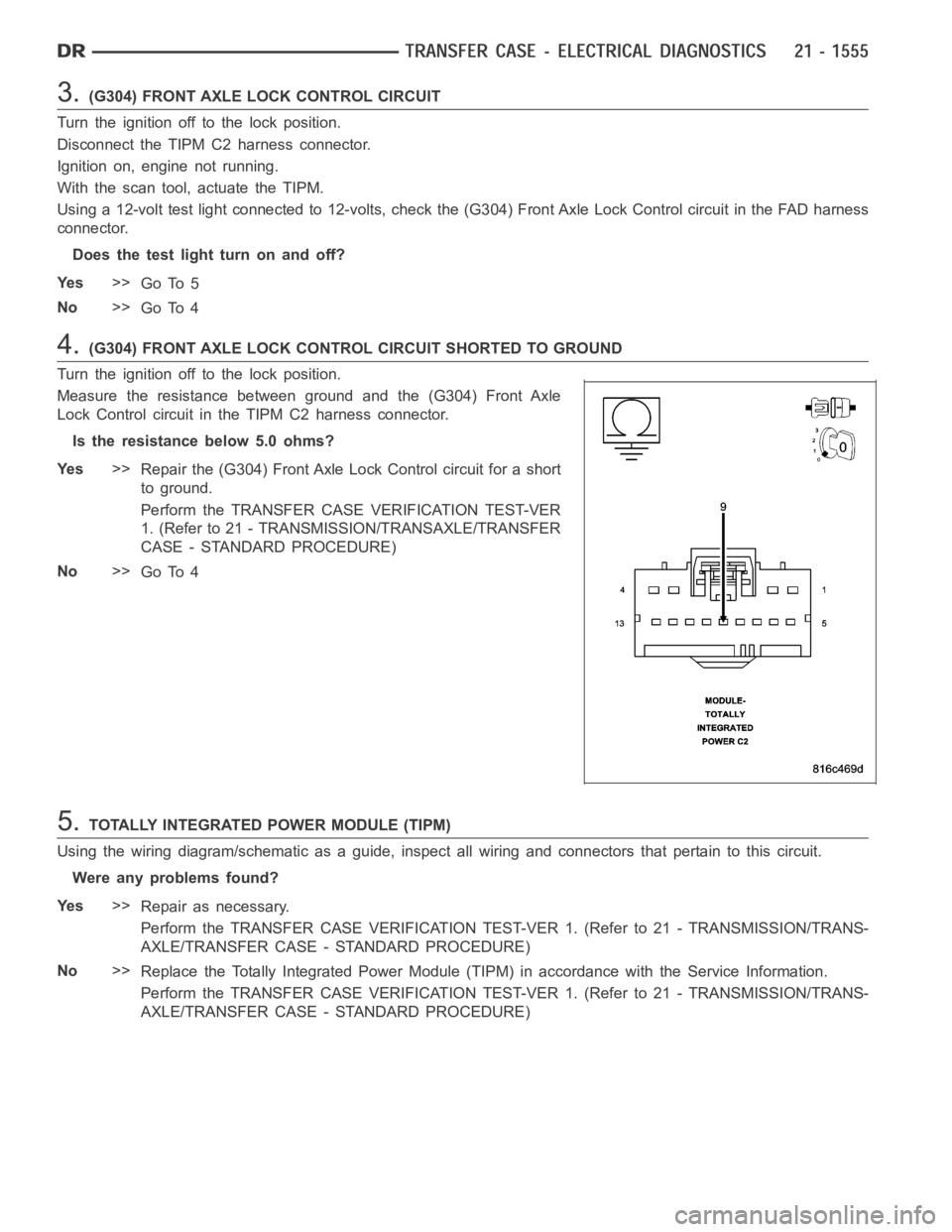
Measure the resistance between ground and the (G304) Front Axle
Lock Control circuit in the TIPM C2 harness connector.
Is the resistance below 5.0 ohms?
Ye s>>
Repair the (G304) Front Axle Lock Control circuit for a short
to ground.
Perform the TRANSFER CASE VERIFICATION TEST-VER
1. (Refer to 21 - TRANSMISSION/TRANSAXLE/TRANSFER
CASE - STANDARD PROCEDURE)
No>>
Go To 4
5.TOTALLY INTEGRATED POWER MODULE (TIPM)
Using the wiring diagram/schematic as a guide, inspect all wiring and connectors that pertain to this circuit.
Were any problems found?
Ye s>>
Repair as necessary.
Perform the TRANSFER CASE VERIFICATION TEST-VER 1. (Refer to 21 - TRANSMISSION/TRANS-
AXLE/TRANSFER CASE - STANDARD PROCEDURE)
No>>
Replace the Totally Integrated Power Module (TIPM) in accordance with theService Information.
Perform the TRANSFER CASE VERIFICATION TEST-VER 1. (Refer to 21 - TRANSMISSION/TRANS-
AXLE/TRANSFER CASE - STANDARD PROCEDURE)
Page 4079 of 5267
When Monitored:
The ignition on. T-Case Switch in 4W/LO position.
Set Condition:
The TIPM detects that the Front Axle Lock Signal circuit is shorted low.
Possible Causes
(A880) FUSED B+ CIRCUIT OPEN
(G303) FRONT AXLE LOCK SIGNAL CIRCUIT OPEN
(G304) FRONT AXLE LOCK CONTROL CIRCUIT OPEN
FRONT AXLE DISCONNECT (FAD) MODULE
TOTALLY INTEGRATED POWER MODULE (TIPM)
Diagnostic Test
1.ACTIVE DTC
CAUTION: Before removing the TIPM harness connectors, clean the connector and locking cam area of dirt
and debris. Failure to do so can result in the connector being jammed or damage to the locking cams on
the harness connector or module. Do not force the assist arm when releasingor installing the harness con-
nector.
Ignition on, engine not running.
With the scan tool, read the TIPM DTCs.
Is the status Active for this DTC?
Ye s>>
Go To 2
No>>
Go To 6
2.(A880) FUSED B+ OPEN
Turn the ignition off to the lock position.
Disconnect the FAD harness connector.
Ignition on, engine not running.
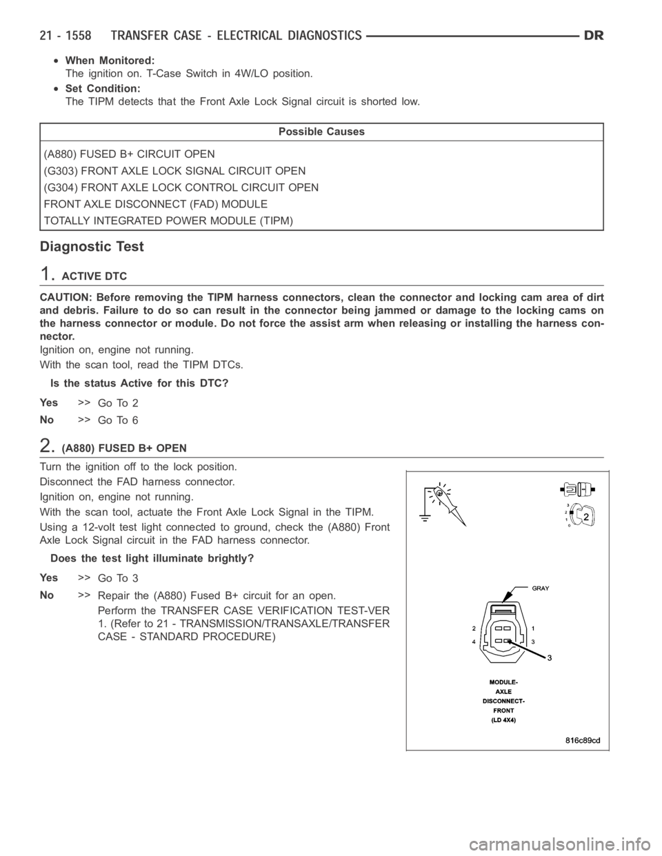
With the scan tool, actuate the Front Axle Lock Signal in the TIPM.
Using a 12-volt test light connected to ground, check the (A880) Front
Axle Lock Signal circuit in the FAD harness connector.
Does the test light illuminate brightly?
Ye s>>
Go To 3
No>>
Repair the (A880) Fused B+ circuit for an open.
Perform the TRANSFER CASE VERIFICATION TEST-VER
1. (Refer to 21 - TRANSMISSION/TRANSAXLE/TRANSFER
CASE - STANDARD PROCEDURE)