2006 DODGE RAM SRT-10 check engine
[x] Cancel search: check enginePage 3645 of 5267
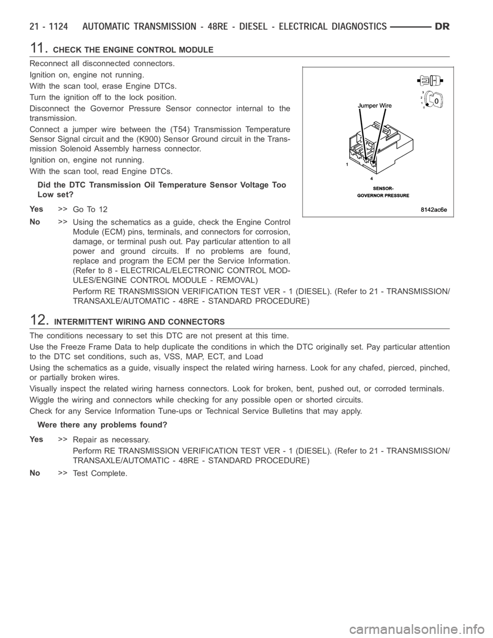
11 .CHECK THE ENGINE CONTROL MODULE
Reconnect all disconnected connectors.
Ignition on, engine not running.
With the scan tool, erase Engine DTCs.
Turn the ignition off to the lock position.
Disconnect the Governor Pressure Sensor connector internal to the
transmission.
Connect a jumper wire between the (T54) Transmission Temperature
Sensor Signal circuit and the (K900) Sensor Ground circuit in the Trans-
mission Solenoid Assembly harness connector.
Ignition on, engine not running.
With the scan tool, read Engine DTCs.
Did the DTC Transmission Oil Temperature Sensor Voltage Too
Low set?
Ye s>>
Go To 12
No>>
Using the schematics as a guide, check the Engine Control
Module (ECM) pins, terminals, and connectors for corrosion,
damage, or terminal push out. Pay particular attention to all
power and ground circuits. If no problems are found,
replace and program the ECM per the Service Information.
(Refer to 8 - ELECTRICAL/ELECTRONIC CONTROL MOD-
ULES/ENGINE CONTROL MODULE - REMOVAL)
Perform RE TRANSMISSION VERIFICATION TEST VER - 1 (DIESEL). (Refer to 21 - TRANSMISSION/
TRANSAXLE/AUTOMATIC - 48RE - STANDARD PROCEDURE)
12.INTERMITTENT WIRING AND CONNECTORS
The conditions necessary to set this DTC are not present at this time.
Use the Freeze Frame Data to help duplicate the conditions in which the DTC originally set. Pay particular attention
to the DTC set conditions, such as, VSS, MAP, ECT, and Load
Using the schematics as a guide, visually inspect the related wiring harness. Look for any chafed, pierced, pinched,
or partially broken wires.
Visually inspect the related wiring harness connectors. Look for broken,bent, pushed out, or corroded terminals.
Wiggle the wiring and connectors while checking for any possible open or shorted circuits.
Check for any Service Information Tune-ups or Technical Service Bulletins that may apply.
Were there any problems found?
Ye s>>
Repair as necessary.
Perform RE TRANSMISSION VERIFICATION TEST VER - 1 (DIESEL). (Refer to 21 - TRANSMISSION/
TRANSAXLE/AUTOMATIC - 48RE - STANDARD PROCEDURE)
No>>
Te s t C o m p l e t e .
Page 3647 of 5267
Theory of Operation
The Output Shaft speed and other inputs are used to determine the current governor pressure. This directly effects
which gear the vehicle is in.
When Monitored:
Continuously with the ignition on, engine running, and gear selector NOT in park or neutral.
Set Condition:
This DTC will set if the vehicle speed (reported from the CAB module) is above 24 Kmh (15 mph), and the
monitored Output Shaft Speed is below 60 RPM for 2.6 seconds.
Possible Causes
PARK/NEUTRAL DTC PRESENT
(T13) SENSOR GROUND CIRCUIT OPEN
(T14) OUTPUT SPEED SENSOR SIGNAL CIRCUIT OPEN
(T13) SENSOR GROUND CIRCUIT SHORT TO ANOTHER CIRCUIT
(T14) OUTPUT SPEED SENSOR SIGNAL CIRCUIT SHORT TO GROUND
(T14) OUTPUT SPEED SENSOR SIGNAL CIRCUIT SHORT TO ANOTHER CIRCUIT
(T13) SENSOR GROUND CIRCUIT SHORT TO VOLTAGE
(T14) OUTPUT SPEED SENSOR SIGNAL CIRCUIT SHORT TO VOLTAGE
OUTPUT SPEED SENSOR
ENGINE CONTROL MODULE
Always perform the Pre-Diagnostic Troubleshooting procedure before proceeding. (Refer to 21 - TRANSMIS-
SION/TRANSAXLE/AUTOMATIC - 48RE - STANDARD PROCEDURE)
Diagnostic Test
1.CHECK IF THE DTC IS CURRENT
Ignition on, engine not running.
With the scan tool, read Engine DTCs.
Record the Freeze Frame data for the reported DTC.
With the scan tool, erase DTCs.
Turn the ignition off to the lock position.
Using the Freeze Frame data recorded earlier, try to duplicate the conditions in which the DTC originally set.
NOTE: It may be necessary to road test the vehicle to duplicate the originalset conditions.
With the scan tool, read Engine DTCs.
Did the DTC reset?
Ye s>>
Go To 2
No>>
Go To 11
2.CHECK IF A PARK/NEUTRAL DTC IS PRESENT
Is there a Park/Neutral DTC present?
Ye s>>
Refer to the Transmission category and perform the appropriate symptom(s).
No>>
Go To 3
Page 3650 of 5267
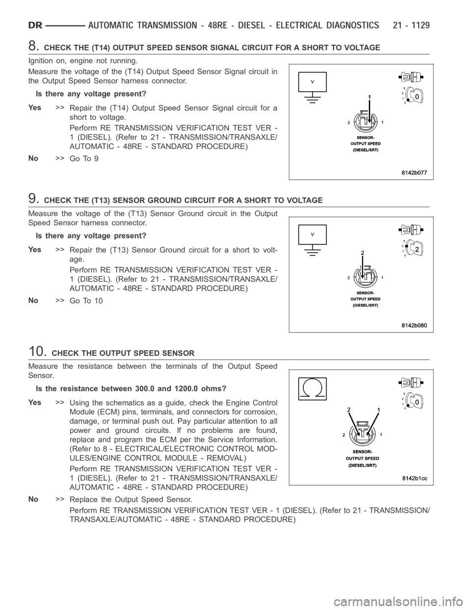
8.CHECK THE (T14) OUTPUT SPEED SENSOR SIGNAL CIRCUIT FOR A SHORT TO VOLTAGE
Ignition on, engine not running.
Measure the voltage of the (T14) Output Speed Sensor Signal circuit in
the Output Speed Sensor harness connector.
Is there any voltage present?
Ye s>>
Repair the (T14) Output Speed Sensor Signal circuit for a
short to voltage.
Perform RE TRANSMISSION VERIFICATION TEST VER -
1 (DIESEL). (Refer to 21 - TRANSMISSION/TRANSAXLE/
AUTOMATIC - 48RE - STANDARD PROCEDURE)
No>>
Go To 9
9.CHECK THE (T13) SENSOR GROUND CIRCUIT FOR A SHORT TO VOLTAGE
Measure the voltage of the (T13) Sensor Ground circuit in the Output
Speed Sensor harness connector.
Is there any voltage present?
Ye s>>
Repair the (T13) Sensor Ground circuit for a short to volt-
age.
Perform RE TRANSMISSION VERIFICATION TEST VER -
1 (DIESEL). (Refer to 21 - TRANSMISSION/TRANSAXLE/
AUTOMATIC - 48RE - STANDARD PROCEDURE)
No>>
Go To 10
10.CHECK THE OUTPUT SPEED SENSOR
Measure the resistance between the terminals of the Output Speed
Sensor.
Is the resistance between 300.0 and 1200.0 ohms?
Ye s>>
Using the schematics as a guide, check the Engine Control
Module (ECM) pins, terminals, and connectors for corrosion,
damage, or terminal push out. Pay particular attention to all
power and ground circuits. If no problems are found,
replace and program the ECM per the Service Information.
(Refer to 8 - ELECTRICAL/ELECTRONIC CONTROL MOD-
ULES/ENGINE CONTROL MODULE - REMOVAL)
Perform RE TRANSMISSION VERIFICATION TEST VER -
1 (DIESEL). (Refer to 21 - TRANSMISSION/TRANSAXLE/
AUTOMATIC - 48RE - STANDARD PROCEDURE)
No>>
Replace the Output Speed Sensor.
Perform RE TRANSMISSION VERIFICATION TEST VER - 1 (DIESEL). (Refer to 21 - TRANSMISSION/
TRANSAXLE/AUTOMATIC - 48RE - STANDARD PROCEDURE)
Page 3653 of 5267
Theory of Operation
The Governor Pressure Solenoid is used to control governor pressure. Governor pressure is used to shift between
first, second, and third gear.
When Monitored:
Continuously with the ignition on.
Set Condition:
This DTC will set if the ECM monitored voltage detected on the Governor Pressure Solenoid Control circuit is
different than the expected voltage. Note: To clear this DTC, it is necessary to drive the vehicle at a sustained
speed which would allow the TCC and/or Overdrive Clutch to operate.
Possible Causes
(T16) TRANSMISSION CONTROL OUTPUT CIRCUIT OPEN
(T16) TRANSMISSION CONTROL OUTPUT CIRCUIT SHORT TO GROUND
(T118) GOVERNOR PRESSURE SOLENOID CONTROL CIRCUIT OPEN
(T118) GOVERNOR PRESSURE SOLENOID CONTROL CIRCUIT SHORT TO GROUND
(T118) GOVERNOR PRESSURE SOLENOID CONTROL CIRCUIT SHORT TO VOLTAGE
(T118) GOVERNOR PRESSURE SOLENOID CONTROL CIRCUIT SHORT TO ANOTHER CIRCUIT
TOTALLY INTEGRATED POWER MODULE (TIPM)
GOVERNOR PRESSURE SOLENOID
ENGINE CONTROL MODULE
Always perform the Pre-Diagnostic Troubleshooting procedure before proceeding. (Refer to 21 - TRANSMIS-
SION/TRANSAXLE/AUTOMATIC - 48RE - STANDARD PROCEDURE)
Diagnostic Test
1.CHECK IF THE DTC P0882 IS PRESENT
Ignition on, engine not running.
With the scan tool, read Engine DTCs.
Is the DTC P0882 present also?
Ye s>>
Refer to the Transmission category and perform the appropriate symptom.
No>>
Go To 2
2.CHECK IF THE DTC IS CURRENT
With the scan tool, read Engine DTCs.
Record the Freeze Frame data for the reported DTC.
With the scan tool, erase DTCs.
Turn the ignition off to the lock position.
Using the Freeze Frame data recorded earlier, try to duplicate the conditions in which the DTC originally set.
NOTE: It may be necessary to road test the vehicle to duplicate the originalset conditions.
With the scan tool, read Engine DTCs.
Did the DTC reset?
Ye s>>
Go To 3
No>>
Go To 13
Page 3654 of 5267
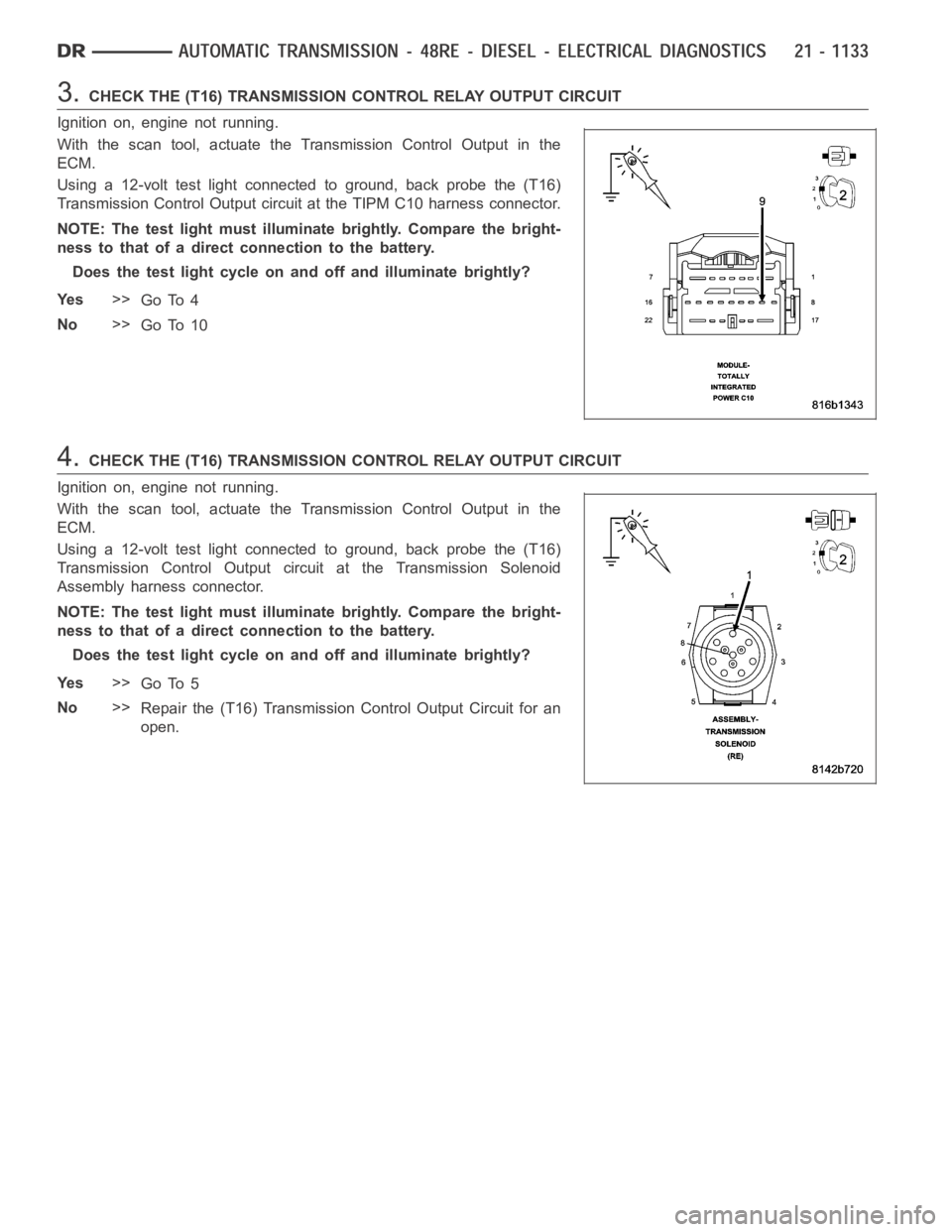
3.CHECK THE (T16) TRANSMISSION CONTROL RELAY OUTPUT CIRCUIT
Ignition on, engine not running.
With the scan tool, actuate the Transmission Control Output in the
ECM.
Using a 12-volt test light connected to ground, back probe the (T16)
Transmission Control Output circuit at the TIPM C10 harness connector.
NOTE: The test light must illuminate brightly. Compare the bright-
ness to that of a direct connection to the battery.
Does the test light cycle on and off and illuminate brightly?
Ye s>>
Go To 4
No>>
Go To 10
4.CHECK THE (T16) TRANSMISSION CONTROL RELAY OUTPUT CIRCUIT
Ignition on, engine not running.
With the scan tool, actuate the Transmission Control Output in the
ECM.
Using a 12-volt test light connected to ground, back probe the (T16)
Transmission Control Output circuit at the Transmission Solenoid
Assembly harness connector.
NOTE: The test light must illuminate brightly. Compare the bright-
ness to that of a direct connection to the battery.
Does the test light cycle on and off and illuminate brightly?
Ye s>>
Go To 5
No>>
Repair the (T16) Transmission Control Output Circuit for an
open.
Page 3656 of 5267
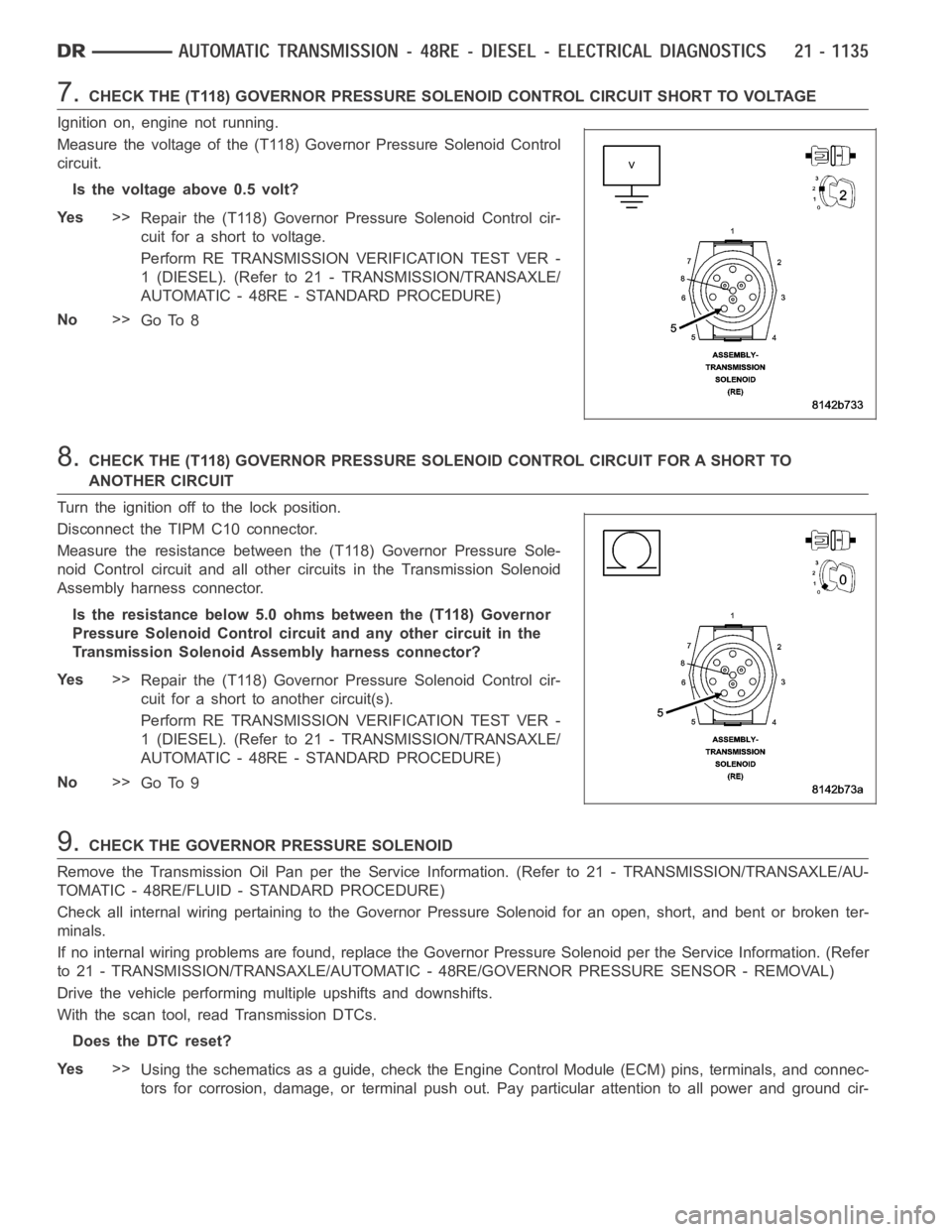
7.CHECK THE (T118) GOVERNOR PRESSURE SOLENOID CONTROL CIRCUIT SHORT TO VOLTAGE
Ignition on, engine not running.
Measure the voltage of the (T118) Governor Pressure Solenoid Control
circuit.
Is the voltage above 0.5 volt?
Ye s>>
Repair the (T118) Governor Pressure Solenoid Control cir-
cuit for a short to voltage.
Perform RE TRANSMISSION VERIFICATION TEST VER -
1 (DIESEL). (Refer to 21 - TRANSMISSION/TRANSAXLE/
AUTOMATIC - 48RE - STANDARD PROCEDURE)
No>>
Go To 8
8.CHECK THE (T118) GOVERNOR PRESSURE SOLENOID CONTROL CIRCUIT FOR A SHORT TO
ANOTHER CIRCUIT
Turn the ignition off to the lock position.
Disconnect the TIPM C10 connector.
Measure the resistance between the (T118) Governor Pressure Sole-
noid Control circuit and all other circuits in the Transmission Solenoid
Assembly harness connector.
Is the resistance below 5.0 ohms between the (T118) Governor
Pressure Solenoid Control circuit and any other circuit in the
Transmission Solenoid Assembly harness connector?
Ye s>>
Repair the (T118) Governor Pressure Solenoid Control cir-
cuit for a short to another circuit(s).
Perform RE TRANSMISSION VERIFICATION TEST VER -
1 (DIESEL). (Refer to 21 - TRANSMISSION/TRANSAXLE/
AUTOMATIC - 48RE - STANDARD PROCEDURE)
No>>
Go To 9
9.CHECK THE GOVERNOR PRESSURE SOLENOID
Remove the Transmission Oil Pan per the Service Information. (Refer to 21 -TRANSMISSION/TRANSAXLE/AU-
TOMATIC - 48RE/FLUID - STANDARD PROCEDURE)
Check all internal wiring pertaining to the Governor Pressure Solenoid for an open, short, and bent or broken ter-
minals.
If no internal wiring problems are found, replace the Governor Pressure Solenoid per the Service Information. (Refer
to 21 - TRANSMISSION/TRANSAXLE/AUTOMATIC - 48RE/GOVERNOR PRESSURE SENSOR - REMOVAL)
Drive the vehicle performing multiple upshifts and downshifts.
With the scan tool, read Transmission DTCs.
Does the DTC reset?
Ye s>>
Using the schematics as a guide, check the Engine Control Module (ECM) pins, terminals, and connec-
tors for corrosion, damage, or terminal push out. Pay particular attentiontoallpowerandgroundcir-
Page 3657 of 5267
cuits. If no problems are found, replace and program the ECM per the ServiceInformation. (Refer to 8
- ELECTRICAL/ELECTRONIC CONTROL MODULES/ENGINE CONTROL MODULE - REMOVAL)
Perform RE TRANSMISSION VERIFICATION TEST VER - 1 (DIESEL). (Refer to 21 - TRANSMISSION/
TRANSAXLE/AUTOMATIC - 48RE - STANDARD PROCEDURE)
No>>
Te s t C o m p l e t e .
Perform RE TRANSMISSION VERIFICATION TEST VER - 1 (DIESEL). (Refer to 21 - TRANSMISSION/
TRANSAXLE/AUTOMATIC - 48RE - STANDARD PROCEDURE)
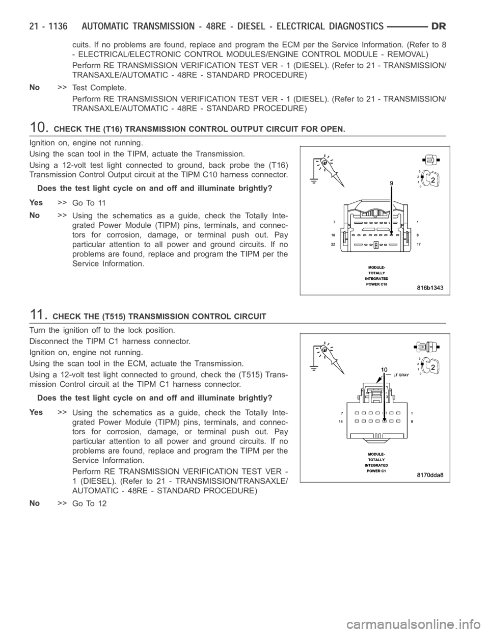
10.CHECK THE (T16) TRANSMISSION CONTROL OUTPUT CIRCUIT FOR OPEN.
Ignition on, engine not running.
Using the scan tool in the TIPM, actuate the Transmission.
Using a 12-volt test light connected to ground, back probe the (T16)
Transmission Control Output circuit at the TIPM C10 harness connector.
Does the test light cycle on and off and illuminate brightly?
Ye s>>
Go To 11
No>>
Using the schematics as a guide, check the Totally Inte-
grated Power Module (TIPM) pins, terminals, and connec-
tors for corrosion, damage, or terminal push out. Pay
particular attention to all power and ground circuits. If no
problems are found, replace and program the TIPM per the
Service Information.
11 .CHECK THE (T515) TRANSMISSION CONTROL CIRCUIT
Turn the ignition off to the lock position.
Disconnect the TIPM C1 harness connector.
Ignition on, engine not running.
Using the scan tool in the ECM, actuate the Transmission.
Using a 12-volt test light connected to ground, check the (T515) Trans-
mission Control circuit at the TIPM C1 harness connector.
Does the test light cycle on and off and illuminate brightly?
Ye s>>
Using the schematics as a guide, check the Totally Inte-
grated Power Module (TIPM) pins, terminals, and connec-
tors for corrosion, damage, or terminal push out. Pay
particular attention to all power and ground circuits. If no
problems are found, replace and program the TIPM per the
Service Information.
Perform RE TRANSMISSION VERIFICATION TEST VER -
1 (DIESEL). (Refer to 21 - TRANSMISSION/TRANSAXLE/
AUTOMATIC - 48RE - STANDARD PROCEDURE)
No>>
Go To 12
Page 3658 of 5267
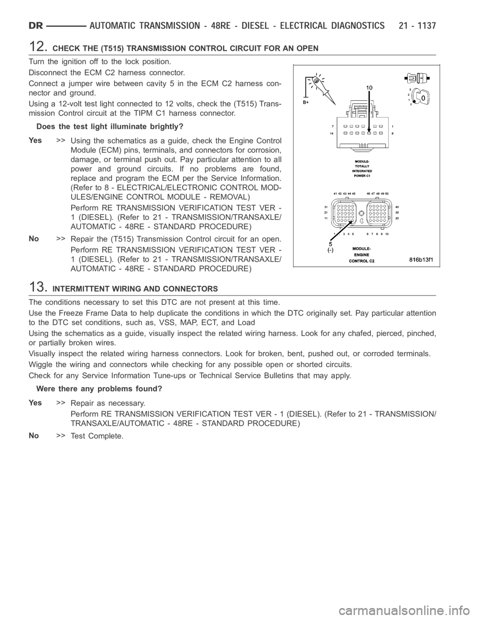
12.CHECK THE (T515) TRANSMISSION CONTROL CIRCUIT FOR AN OPEN
Turn the ignition off to the lock position.
Disconnect the ECM C2 harness connector.
Connect a jumper wire between cavity 5 in the ECM C2 harness con-
nector and ground.
Using a 12-volt test light connected to 12 volts, check the (T515) Trans-
mission Control circuit at the TIPM C1 harness connector.
Does the test light illuminate brightly?
Ye s>>
Using the schematics as a guide, check the Engine Control
Module (ECM) pins, terminals, and connectors for corrosion,
damage, or terminal push out. Pay particular attention to all
power and ground circuits. If no problems are found,
replace and program the ECM per the Service Information.
(Refer to 8 - ELECTRICAL/ELECTRONIC CONTROL MOD-
ULES/ENGINE CONTROL MODULE - REMOVAL)
Perform RE TRANSMISSION VERIFICATION TEST VER -
1 (DIESEL). (Refer to 21 - TRANSMISSION/TRANSAXLE/
AUTOMATIC - 48RE - STANDARD PROCEDURE)
No>>
Repair the (T515) Transmission Control circuit for an open.
Perform RE TRANSMISSION VERIFICATION TEST VER -
1 (DIESEL). (Refer to 21 - TRANSMISSION/TRANSAXLE/
AUTOMATIC - 48RE - STANDARD PROCEDURE)
13.INTERMITTENT WIRING AND CONNECTORS
The conditions necessary to set this DTC are not present at this time.
Use the Freeze Frame Data to help duplicate the conditions in which the DTC originally set. Pay particular attention
to the DTC set conditions, such as, VSS, MAP, ECT, and Load
Using the schematics as a guide, visually inspect the related wiring harness. Look for any chafed, pierced, pinched,
or partially broken wires.
Visually inspect the related wiring harness connectors. Look for broken,bent, pushed out, or corroded terminals.
Wiggle the wiring and connectors while checking for any possible open or shorted circuits.
Check for any Service Information Tune-ups or Technical Service Bulletins that may apply.
Were there any problems found?
Ye s>>
Repair as necessary.
Perform RE TRANSMISSION VERIFICATION TEST VER - 1 (DIESEL). (Refer to 21 - TRANSMISSION/
TRANSAXLE/AUTOMATIC - 48RE - STANDARD PROCEDURE)
No>>
Te s t C o m p l e t e .