Page 1800 of 2893
����
Driver’s Seat
20-122 Seats
Front Seat Frame Replacement (cont’d)
A
B
C
D
Fastener Locations
:Clip,3
A
E
Check the operation of the driver’")
����
�(�#�'���������������
����������������� �����)����
Driver’s Seat
20-122 Seats
Front Seat Frame Replacement (cont’d)
A
B
C
D
Fastener Locations
:Clip,3
A
E
Check the operation of the driver’s seat position sensor
after any of these actions (see page 24-29):
Driver’s seat position sensor replacement
Cover plate (front side of driver’s seat slide rail) replacement
NOTE: Put on gloves to protect your hands.
Apply oil to the pivot portions of the slide lock.
Apply multipurpose grease to the sliding portions and pivot portions of the seat tracks.
If the side airbag has deployed, replace the seat frame and related pieces with new ones (see page
24-185).
1. Remove the front seat (see page 20-118).
2. Remove these items: Front seat-back cover/pad (see page 20-123)
Front seat cushion cover/pad (see page 20-127)
Driver’s seat position sensor (see page 24-211)
Front seat belt buckle (see page 24-6) 3. Remove the clips, then remove the recline inner
covers (A), the outer upper rail cover (B), the inner
upper rail cover (C) and the module holder (D) from
the seat frame (E).
4. Install the new seat frame in the reverse order of removal, and note these items:
Make sure the driver’s seat position sensor connector is plugged in properly.
If the clips are damaged or stress-whitened, replace them with new ones.
Push the clips into place securely.
Make sure the seat wiring harnesses are routed properly and not pinched.
08/08/21 15:03:56 61SNR030_200_0124
ProCarManuals.com
DYNOMITE -2009-
Page 1815 of 2893
���
���
�(�#�'���������������
����������������� �����)����
20-13620-136 Seats
Rear Seat-back Latch Replacement
(cont’d)
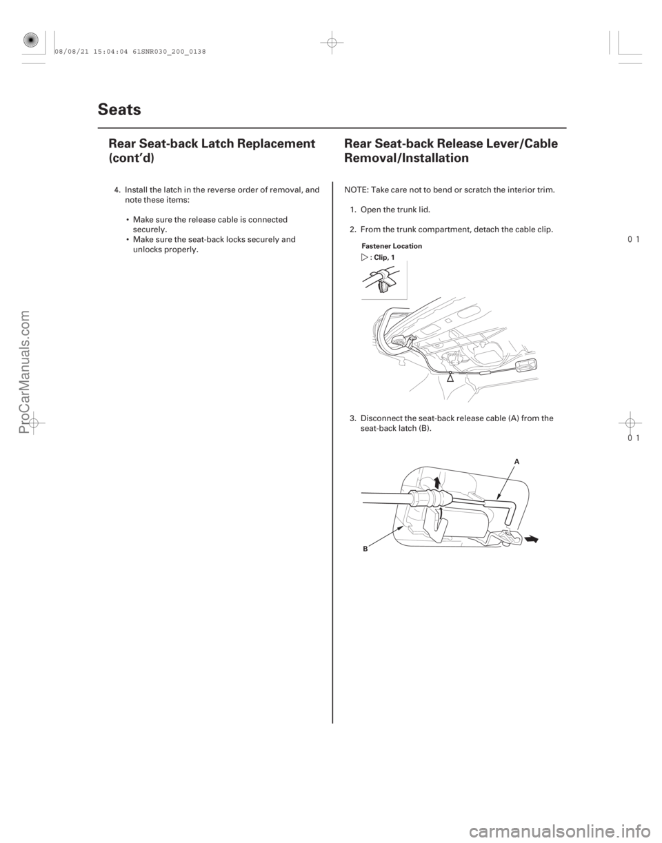
Rear Seat-back Release Lever/Cable
Removal/Installation
Fastener Location
:Clip,1
A
B
4. Install the latch in the reverse order of removal, and note these items:
Make sure the release cable is connected securely.
Make sure the seat-back locks securely and unlocks properly. NOTE: Take care not to bend or scratch the interior trim.
1. Open the trunk lid.
2. From the trunk compartment, detach the cable clip.
3. Disconnect the seat-back release cable (A) from the seat-back latch (B).
08/08/21 15:04:04 61SNR030_200_0138
ProCarManuals.com
DYNOMITE -2009-
Page 1816 of 2893
���
���
�(�#�'���������������
����������������� �����)����
20-13620-136 Seats
Rear Seat-back Latch Replacement
(cont’d)
Rear Seat-back Release Lever/Cable
Removal/Installation
Fastener Location
:Clip,1
A
B
4. Install the latch in the reverse order of removal, and note these items:
Make sure the release cable is connected securely.
Make sure the seat-back locks securely and unlocks properly. NOTE: Take care not to bend or scratch the interior trim.
1. Open the trunk lid.
2. From the trunk compartment, detach the cable clip.
3. Disconnect the seat-back release cable (A) from the seat-back latch (B).
08/08/21 15:04:04 61SNR030_200_0138
ProCarManuals.com
DYNOMITE -2009-
Page 1817 of 2893
����
���
�(�#�'���������������
�������
��������� �����)����
Special Tools Required
20-13720-137
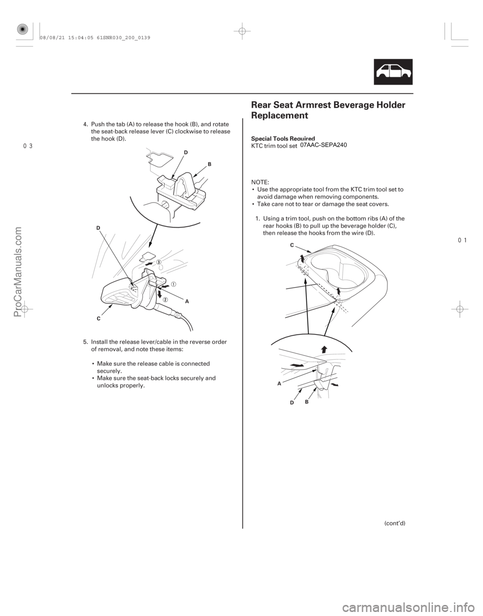
Rear Seat Armrest Beverage Holder
Replacement
A B
C
D
D
AB
C
D
4. Push the tab (A) to release the hook (B), and rotate the seat-back release lever (C) clockwise to release
the hook (D).
5. Install the release lever/cable in the reverse order of removal, and note these items:
Make sure the release cable is connected securely.
Make sure the seat-back locks securely and unlocks properly. KTC trim tool set SOJATP2014
NOTE:
Use the appropriate tool from the KTC trim tool set to avoid damage when removing components.
Take care not to tear or damage the seat covers.
1. Using a trim tool, push on the bottom ribs (A) of the rear hooks (B) to pull up the beverage holder (C),
then release the hooks from the wire (D).
(cont’d)
08/08/21 15:04:05 61SNR030_200_0139
ProCarManuals.com
DYNOMITE -2009-
Page 1818 of 2893
����
���
�(�#�'���������������
�������
��������� �����)����
Special Tools Required
20-13720-137
Rear Seat Armrest Beverage Holder
Replacement
A B
C
D
D
AB
C
D
4. Push the tab (A) to release the hook (B), and rotate the seat-back release lever (C) clockwise to release
the hook (D).
5. Install the release lever/cable in the reverse order of removal, and note these items:
Make sure the release cable is connected securely.
Make sure the seat-back locks securely and unlocks properly. KTC trim tool set SOJATP2014
NOTE:
Use the appropriate tool from the KTC trim tool set to avoid damage when removing components.
Take care not to tear or damage the seat covers.
1. Using a trim tool, push on the bottom ribs (A) of the rear hooks (B) to pull up the beverage holder (C),
then release the hooks from the wire (D).
(cont’d)
08/08/21 15:04:05 61SNR030_200_0139
ProCarManuals.com
DYNOMITE -2009-
Page 1840 of 2893
����
20-155
Trunk Lid
Trunk Lid Adjustment
A
B
C D G
H
E
6x1.0mm
18 N·m
(1.8 kgf·m, 13 lbf·ft)
E
6x1.0mm
9.8 N·m (1.0 kgf·m, 7.2 lbf·ft)
H F
F
1")
���
�(�#�'�����������
���������������������"�����)����
20-155
Trunk Lid
Trunk Lid Adjustment
A
B
C D G
H
E
6x1.0mm
18 N·m
(1.8 kgf·m, 13 lbf·ft)
E
6x1.0mm
9.8 N·m (1.0 kgf·m, 7.2 lbf·ft)
H F
F
1. Remove the rear shelf (see page 20-78).
2. Pry up on the notch (A) to release the rear hooks (B) and pivot the striker trim cap (C) on the front hooks (D), thenremove the cap. Slightly loosen each bolt (E).
3. Adjust the trunk lid alignment in the following sequence: Adjust the trunk lid hinges (F) right and left, as well as forward and rearward, by using the elongated holes. Takecare not to hit the rear window when loosening the bolts.
Turn the trunk lid edge cushions (G), in or out as necessary, to make the trunk lid fit flush with the body at the rear and side edges.
Adjust the fit between the trunk lid and the trunk lid opening by moving the striker (H).
4. Tighten the bolts to the specified torque.
5. Make sure the trunk lid opens properly and locks securely.
6. Reinstall all removed parts.
08/08/21 15:04:57 61SNR030_200_0157
ProCarManuals.com
DYNOMITE -2009-
Page 1841 of 2893
����
Special Tool Required
20-156
Trunk Lid
Trunk Lid Torsion Bar Replacement
B
A
A
B
B
A
07AAF-SNAA100 A
A B
=Normal position
=Higher")
���
��������
���
�(�#�'�����������
�������������������
� �����)����
Special Tool Required
20-156
Trunk Lid
Trunk Lid Torsion Bar Replacement
B
A
A
B
B
A
07AAF-SNAA100 A
A B
=Normal position
=Higher tension
Torsion bar assembly tool 07AAF-SNAA100
1. Remove the torsion bars (A) from the torsion bar center clip (B).
2. Put on gloves to protect your hands. Remove the torsion bars with the torsion bar assembly tool
from both trunk lid hinges. First remove the left
torsion bar (A), then remove the right torsion bar
(B). 3. Remove the torsion bar center clip (A) from the
body.
4. Install the torsion bar in the reverse order of removal, and note these items:
The shapes of the left torsion bar (A) and the right torsion bar (B) are shown. Install the torsion
bars properly.
Adjust the torsion bars forward or rearward with the torsion bar assembly tool.
The torsion bars were installed at the factory in the normal position, as shown.
Make sure the trunk lid opens properly and locks securely.
08/08/21 15:04:58 61SNR030_200_0158
ProCarManuals.com
DYNOMITE -2009-
Page 1843 of 2893
���
����
�(�#�'�����������
���������������������"�����)����
20-158 Fuel Fill Door
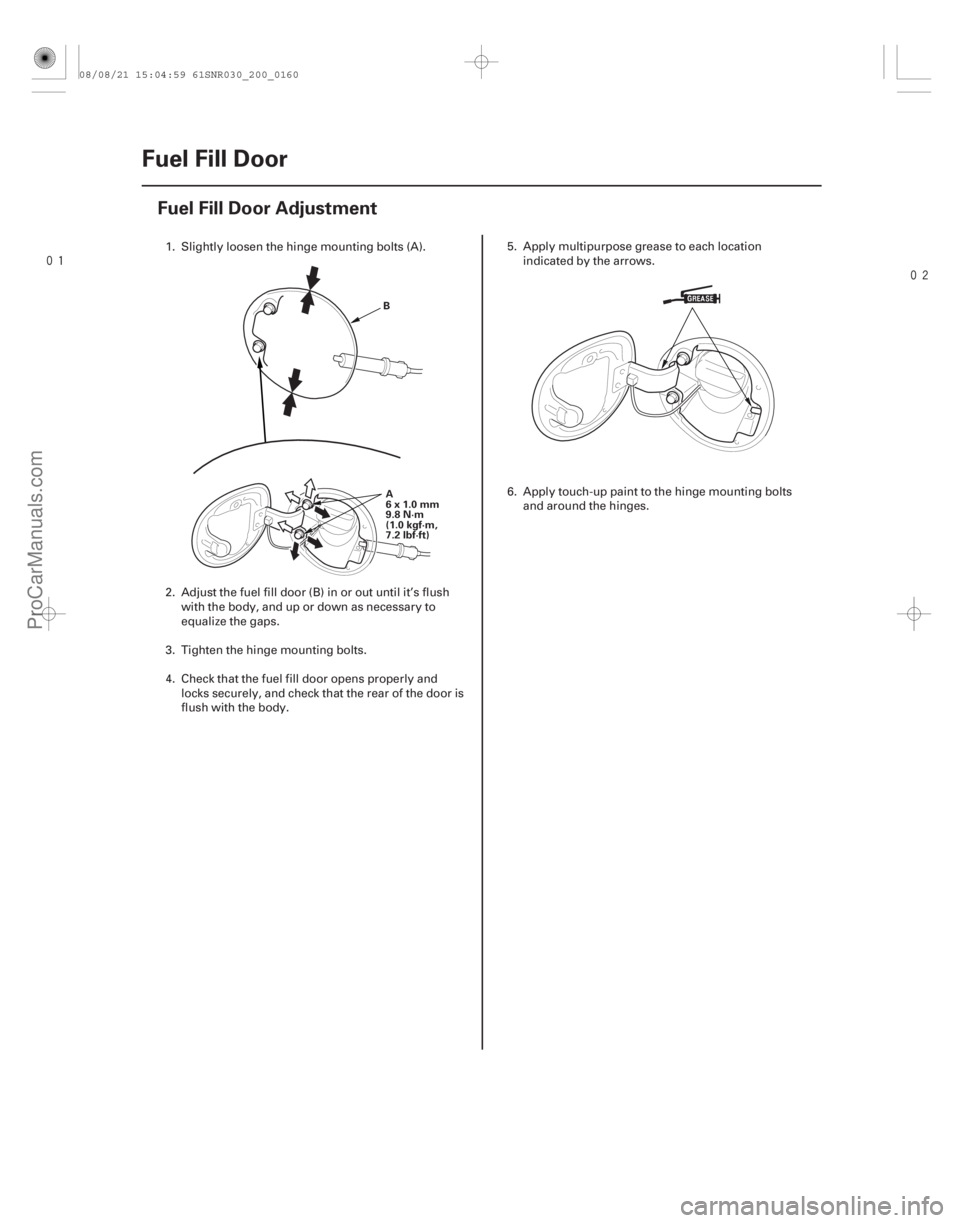
Fuel Fill Door Adjustment
B
A
6x1.0mm
9.8 N·m
(1.0 kgf·m,
7.2 lbf·ft)
1. Slightly loosen the hinge mounting bolts (A).
2. Adjust the fuel fill door (B) in or out until it’s flush with the body, and up or down as necessary to
equalize the gaps.
3. Tighten the hinge mounting bolts.
4. Check that the fuel fill door opens properly and locks securely, and check that the rear of the door is
flush with the body. 5. Apply multipurpose grease to each location
indicated by the arrows.
6. Apply touch-up paint to the hinge mounting bolts and around the hinges.
08/08/21 15:04:59 61SNR030_200_0160
ProCarManuals.com
DYNOMITE -2009-