Page 1774 of 2893
��������� ����
����
20-97
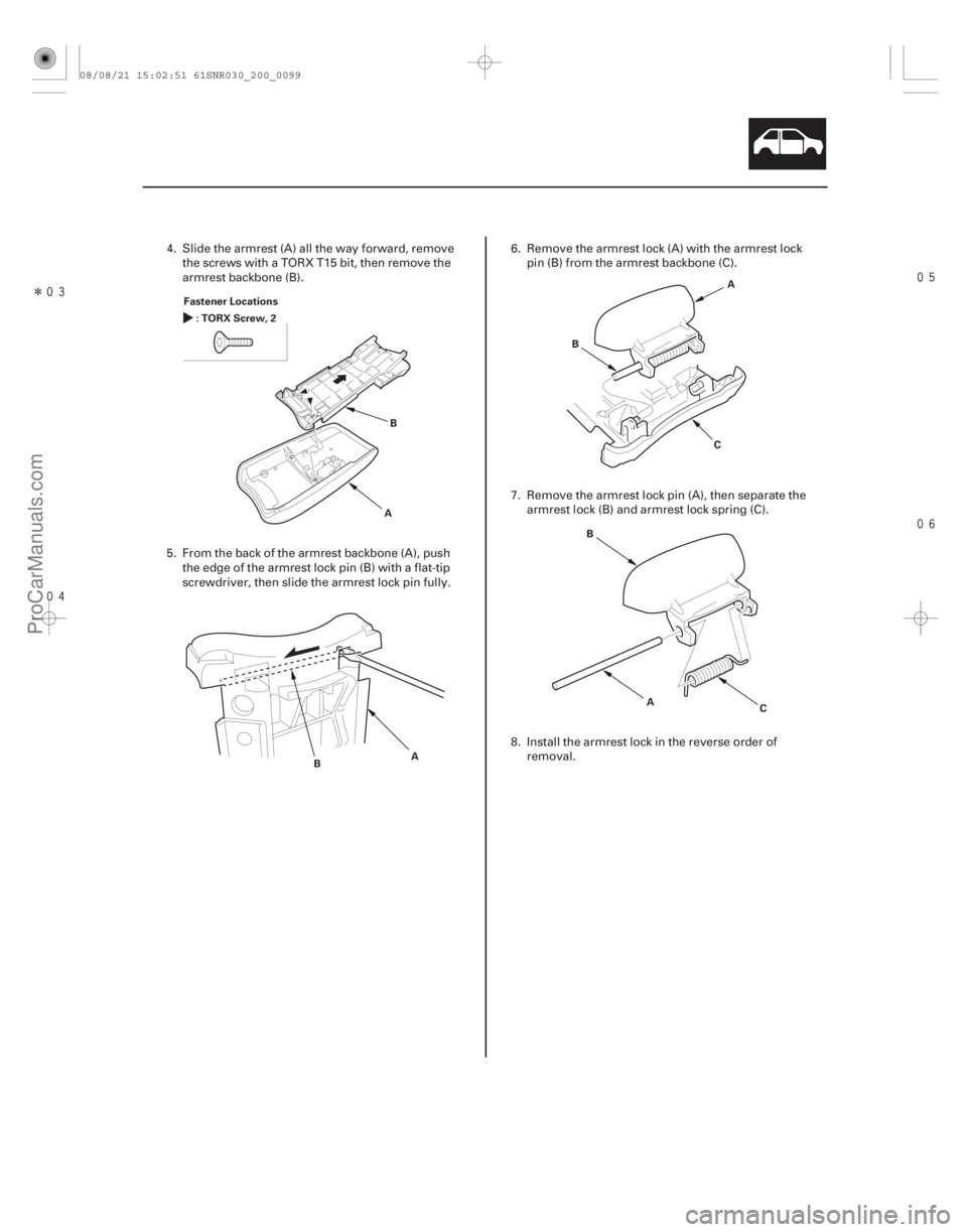
Fastener Locations
:TORXScrew,2
AB
B A A
B
C
A
B
C
4. Slide the armrest (A) all the way forward, removethe screws with a TORX T15 bit, then remove the
armrest backbone (B).
5. From the back of the armrest backbone (A), push the edge of the armrest lock pin (B) with a flat-tip
screwdriver, then slide the armrest lock pin fully. 6. Remove the armrest lock (A) with the armrest lock
pin (B) from the armrest backbone (C).
7. Remove the armrest lock pin (A), then separate the armrest lock (B) and armrest lock spring (C).
8. Install the armrest lock in the reverse order of removal.
08/08/21 15:02:51 61SNR030_200_0099
ProCarManuals.com
DYNOMITE -2009-
Page 1780 of 2893
�
�� ���
�(�#������������������������
��������� �����)����
20-10320-103
Driver’s Dashboard Undercover
Removal/Installation Center Pocket Removal/I")
���
�(�#�'�����������������������
�������
� �����)�
�� ���
�(�#�'�����������������������
��������� �����)����
20-10320-103
Driver’s Dashboard Undercover
Removal/Installation Center Pocket Removal/Installation
Fastener Locations
:Clip,2
C DE AB Fastener Locations
:Screw,4
A
NOTE: Take care not to scratch the dashboard and
related parts.1. Remove the driver’s dashboard undercover (A). –1 Turn the lock knob (B) 90 °.
–2 Gently pull down the rear edge to detach theclips.
–3 Pull the undercover away to release the pin (C) from the holder (D).
–4 For some models: If equipped with a foot light illumination, disconnect the foot light
illumination connector (E).
2. Install the undercover in the r everse order of
removal, and note these items:
Make sure the foot light illumination connector is plugged in properly (for some models).
If the clips are damaged or stress-whitened, replace them with new ones.
Push the clips into place securely. NOTE: Take care not to scratch the dashboard and
related parts.
1. Disassemble the dashboard/steering hanger beam (see page 20-114).
2. Remove the screws, then remove the center pocket (A).
3. Install the center pocket in the reverse order of removal.
08/08/21 15:02:54 61SNR030_200_0105
ProCarManuals.com
DYNOMITE -2009-
Page 1787 of 2893
��������
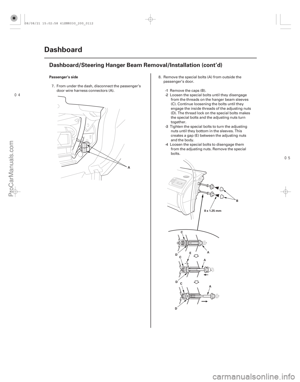
Passenger’s side
20-110 Dashboard
Dashboard/Steering Hanger Beam Removal/Installation (cont’d)
A
A
B
C
D E
A
C
A
C
D
D 8x1.25mm
7. From under the dash, disconnect the passenger’s
door wire harness connectors (A). 8. Remove the special bolts (A) from outside the
passenger’s door.
–1 Remove the caps (B).
–2 Loosen the special bolts until they disengage from the threads on the hanger beam sleeves
(C). Continue loosening the bolts until they
engage the inside threads of the adjusting nuts
(D). The thread lock on the special bolts makes
the special bolts and the adjusting nuts turn
together.
–3 Tighten the special bolts to turn the adjusting nuts until they bottom in the sleeves. This
creates a gap (E) between the adjusting nuts
and the body.
–4 Loosen the special bolts to disengage them from the adjusting nuts. Remove the special
bolts.
08/08/21 15:02:58 61SNR030_200_0112
ProCarManuals.com
DYNOMITE -2009-
Page 1788 of 2893
����
��������
20-111
A
B
C
BC
A
21 mm (0.83 in.) 6x1.0mm
9.8 N·m
(1.0 kgf·m,
7.2 lbf·ft)
A
B
D
D
8x1.25mm
22 N·m
(2.2 kgf·m, 16 lbf·ft)
BB
D
D
6x1.0mm
9.8 N·m
(1.0 kgf·m,
7.2 lbf·ft)
C
8x1.25mm
22 N·m
(2.2 kgf·m, 16 lbf·ft)
Fastener Locations
:Bolt,3 :Bolt,1 :Bolt,4
B CD
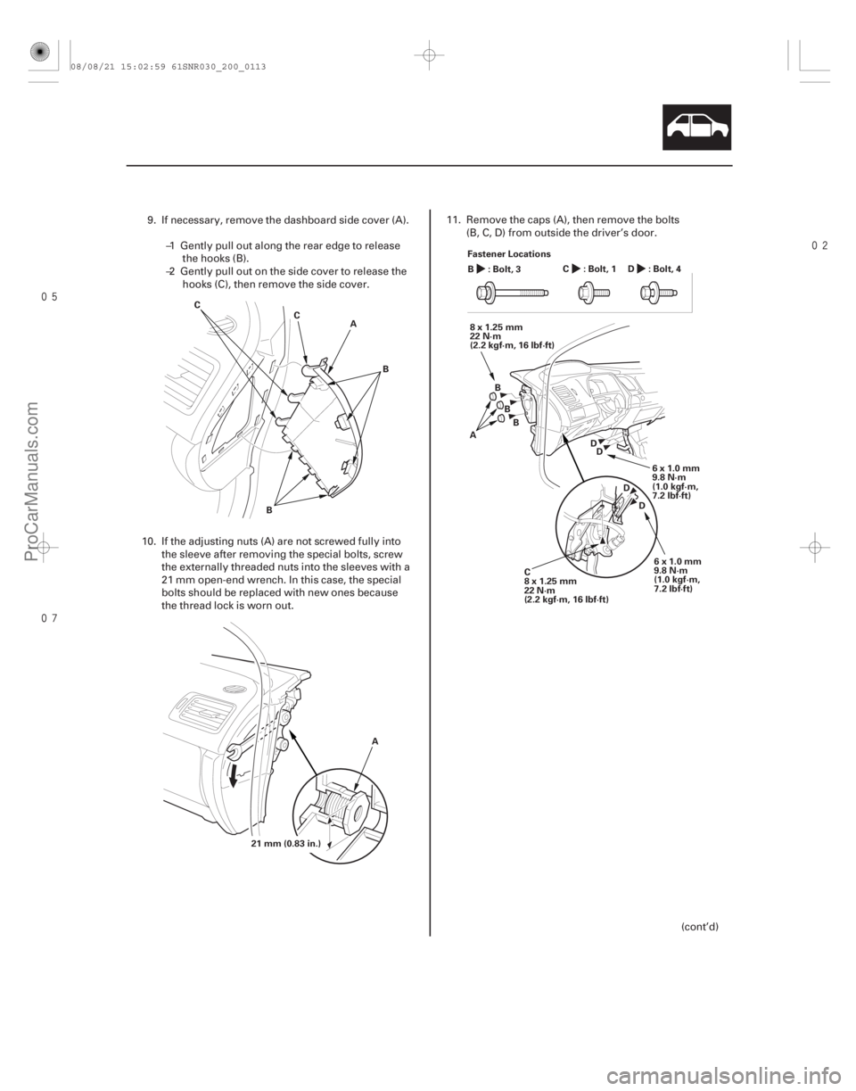
9. If necessary, remove the dashboard side cover (A).
–1 Gently pull out along the rear edge to releasethe hooks (B).
–2 Gently pull out on the side cover to release the hooks (C), then remove the side cover.
10. If the adjusting nuts (A) are not screwed fully into the sleeve after removing the special bolts, screw
the externally threaded nuts into the sleeves with a
21 mm open-end wrench. In this case, the special
bolts should be replaced with new ones because
the thread lock is worn out. 11. Remove the caps (A), then remove the bolts
(B, C, D) from outside the driver’s door.
(cont’d)
08/08/21 15:02:59 61SNR030_200_0113
ProCarManuals.com
DYNOMITE -2009-
Page 1790 of 2893
 A
B
C
A
B
C
B C
14. Install the dashboard in the r
everse order of
removal, and note these items:")
�
�
Special bolt tightening on passenger’s side
20-113
A
8x1.25mm
22 N·m (2.2 kgf·m, 16 lbf·ft) A
B
C
A
B
C
B C
14. Install the dashboard in the r
everse order of
removal, and note these items:
Before tightening the bolts, make sure the wire harnesses are not pinched.
Make sure the connectors are plugged in properly, and the antenna lead and each cable
are connected properly.
Before reinstalling the dashboard, screw the special bolts (A) into the adjusting nuts (B), and
check that they turn together. If they do not turn
together, replace the special bolts.
After setting the dashboard in the body, reinstall all of the mounting bolts but do not tighten them.
First tighten the driver’s side bracket bolts to the
specified torque. Next, loosen the special bolts to
turn the adjusting nuts out of the sleeves (C) until
the nuts contact the body. Then tighten the
special bolts to the specified torque.
Tighten all remaining mounting bolts to the specified torque.
Apply medium strength liquid thread lock to the bolts securing the center bracket and the
dashboard before reinstallation.
Check for any DTCs that may have been set during repairs, and clear them.
Do the battery terminal reconnection procedure (see page 22-68).
08/08/21 15:02:59 61SNR030_200_0115
ProCarManuals.com
DYNOMITE -2009-
Page 1794 of 2893
����
Resetting Head Restraint Position
Inspection
20-117
Front Seat Active Head Restraint Inspection
A
B
Locked B BB
Full stroke Normal
250")
���
����
����
�(�#�'���������������
���������
�����
�"�����)����
Resetting Head Restraint Position
Inspection
20-117
Front Seat Active Head Restraint Inspection
A
B
Locked B BB
Full stroke Normal
250 mm
(9.84 in.)
A
B
C
D
250 mm
(9.84 in.)
Above50mm(2.0in.)
(Level)
A
NOTE: If the vehicle has been in a collision, always
inspect the active head restraint, even if they appear
reusable, by doing the following procedure.1. Push the head restraint (A) forward fully from the locked position to release the inertial lock (B).
2. Slowly raise the head restraint into the normal position. 3. Fold the seat-back forward, then recline the seat-
back to the first lock position, and adjust the head
restraint to the highest position.
4. Apply masking tape on the top of the head restraint.
5. Make marks (A) on both sides at 250 mm (9.84 in.) upward from the roots of the head restraint frame
(B) along the back of the head restraint (C) surface.
Make a center of these points as a datum point (D).
6. Push the head restraint (A) forward, and measure the level amount of the head restraint movement.
The head restraint should move than 50 mm (2.0 in.)
without resistance. If it is less than 50 mm (0.2 in.),
or the head restraint does not move smoothly,
replace the seat frame assembly:
Passenger’s seat (see page 20-120)
Driver’s seat (see page 20-122)
08/08/21 15:03:06 61SNR030_200_0119
ProCarManuals.com
DYNOMITE -2009-
Page 1797 of 2893
�
��
Passenger’s Seat
20-12020-120 Seats
Front Seat Removal/Installation
(cont’d)
Front Seat Frame Replacement
Fastener Locations
:Bolt,4
10x")
���
���
�(�#�'���������������
����������������� �����)�
��
Passenger’s Seat
20-12020-120 Seats
Front Seat Removal/Installation
(cont’d)
Front Seat Frame Replacement
Fastener Locations
:Bolt,4
10x1.25mm
34 N·m
(3.5 kgf·m, 25 lbf·ft) A
A
B
C
Fastener Locations
:Clip,4
A
9. With the help of an assistant, carefully remove thefront seat through the front door opening.
10. Install the seat in the reverse order of removal, and note these items:
Apply medium strength liquid thread lock to the seat mounting bolts before reinstallation.
Tighten the seat mounting bolts to the specified torque in the sequence shown. Slide the seat (A)
all the way back and tighten and , then slide
it forward and tighten and . The driver’s seat
is shown; the passenger’s seat is similar.
Tighten the bolts by hand first, then tighten them to specification with a torque wrench.
Make sure each connector is plugged in properly.
Check for any DTCs that may have been set during repairs, and clear them.
Do the battery terminal reconnection procedure (see page 22-68). Calibrate the ODS unit after any of these actions
(see page 24-27):
Front passenger’s seat replacement (including any seat components)
Replacement of the front seat weight sensors
After a vehicle collision
NOTE: Put on gloves to protect your hands.
Apply oil to the pivot portions of the slide locks.
Apply multipurpose grease to the sliding portions of the seat tracks.
If the side airbag has deployed, replace the seat frame and related pieces with new ones (see page
24-185).
1. Remove the front seat (see page 20-118).
2. Remove these items: Front seat-back cover (see page 20-123)
Front seat cushion cover (see page 20-127)
ODS unit (see page 24-209)
Front seat belt buckle (see page 24-6)
3. Remove the clips, then remove the recline inner covers (A) and module holder (B) from the seat
frame (C).
08/08/21 15:03:55 61SNR030_200_0122
ProCarManuals.com
DYNOMITE -2009-
Page 1798 of 2893
�
��
Passenger’s Seat
20-12020-120 Seats
Front Seat Removal/Installation
(cont’d)
Front Seat Frame Replacement
Fastener Locations
:Bolt,4
10x")
���
���
�(�#�'���������������
����������������� �����)�
��
Passenger’s Seat
20-12020-120 Seats
Front Seat Removal/Installation
(cont’d)
Front Seat Frame Replacement
Fastener Locations
:Bolt,4
10x1.25mm
34 N·m
(3.5 kgf·m, 25 lbf·ft) A
A
B
C
Fastener Locations
:Clip,4
A
9. With the help of an assistant, carefully remove thefront seat through the front door opening.
10. Install the seat in the reverse order of removal, and note these items:
Apply medium strength liquid thread lock to the seat mounting bolts before reinstallation.
Tighten the seat mounting bolts to the specified torque in the sequence shown. Slide the seat (A)
all the way back and tighten and , then slide
it forward and tighten and . The driver’s seat
is shown; the passenger’s seat is similar.
Tighten the bolts by hand first, then tighten them to specification with a torque wrench.
Make sure each connector is plugged in properly.
Check for any DTCs that may have been set during repairs, and clear them.
Do the battery terminal reconnection procedure (see page 22-68). Calibrate the ODS unit after any of these actions
(see page 24-27):
Front passenger’s seat replacement (including any seat components)
Replacement of the front seat weight sensors
After a vehicle collision
NOTE: Put on gloves to protect your hands.
Apply oil to the pivot portions of the slide locks.
Apply multipurpose grease to the sliding portions of the seat tracks.
If the side airbag has deployed, replace the seat frame and related pieces with new ones (see page
24-185).
1. Remove the front seat (see page 20-118).
2. Remove these items: Front seat-back cover (see page 20-123)
Front seat cushion cover (see page 20-127)
ODS unit (see page 24-209)
Front seat belt buckle (see page 24-6)
3. Remove the clips, then remove the recline inner covers (A) and module holder (B) from the seat
frame (C).
08/08/21 15:03:55 61SNR030_200_0122
ProCarManuals.com
DYNOMITE -2009-