Page 1653 of 2893
.
10. Me")
��������
�µ
�µ
�µ
�µ
YES
NO
YES
NO
19-161
YAW RATE-LATERAL ACCELERATION SENSOR
5P CONNECTOR
YEL YAW RATE-LATERAL ACCELERATION SENSOR
5P CONNECTOR
BLK
9. Turn the ignition switch to ON (II).
10. Measure the voltage between yaw rate-lateral acceleration sensor 5P connector terminal No. 1
and body ground.
Go to step 11.
Check the No. 4 (7.5 A) fuse in the under-dash
fuse/relay box. If the fuse is OK, repair open in the
wirebetweentheNo.4(7.5A)fuseandyawrate-
lateral acceleration sensor. 11. Turn the ignition switch to LOCK (0).
12. Reconnect the yaw rate-lateral acceleration sensor
5P connector.
13. Turn the ignition switch to ON (II).
14. Measure the voltage between yaw rate-lateral acceleration sensor 5P connector terminal No. 5
and body ground.
Replace the yaw rate-lateral acceleration
sensor (see page 19-169).
Repair open in the wire between the yaw rate-
lateral acceleration sensor and body ground
(G602).
Wire side of female terminals
Wire side of female terminals
Is there battery voltage?Is t her e 0.1 V or l ess?
08/08/21 15:06:43 61SNR030_190_0161
ProCarManuals.com
DYNOMITE -2009-
Page 1654 of 2893
�����(�#���������� �����
�������(�������
�������)����
�µ
�µ �µ
�µ
�µ
�µ
DTC 107-22: DTC 108-21:
YES
NO YES
NO
YES
NO
19-16219-162VSA System Compone")
�(�#�'��������� �����
�������(���������������)�����(�#�'��������� �����
�������(�������
�������)����
�µ
�µ �µ
�µ
�µ
�µ
DTC 107-22: DTC 108-21:
YES
NO YES
NO
YES
NO
19-16219-162VSA System Components
DTC Troubleshooting (cont’d)
Central Processing Unit (CPU)
Internal Circuit Malfunction Steering Angle Sensor
Malfunction
1. Turn the ignition switch to LOCK (0) to cool the VSA
modulator-control unit, and wait 1 hour or more.
2. Turn the ignition switch to ON (II).
3. Clear the DTC with the HDS.
4. Turn the ignition switch to LOCK (0), then turn it to ON (II) again.
5. Check for DTCs with the HDS.
Replace the VSA modulator-control unit
(see page 19-171).
The system is OK at this time. 1. Turn the ignition switch to ON (II).
2. Clear the DTC with the HDS.
3. Test-drive the vehicle.
NOTE: Drive the vehicle on the road, not on a lift.
4. Check for DTCs with the HDS.
Go to step 5.
Intermittent failure, the system is OK at this
time.
5. Turn the ignition switch to LOCK (0).
6. Substitute a known-good steering angle sensor (see page 19-168).
7. Turn the ignition switch to ON (II).
8. Clear the DTC with the HDS.
9. Test-drive the vehicle. NOTE: Drive the vehicle on the road, not on a lift.
10. Check for DTCs with the HDS.
Replace the VSA modulator-control unit
(see page 19-171).
Replace the original steering angle sensor
(see page 19-168).
I s DT C 107 -22 i nd i cat ed ? I s DT C 108-21 i nd i cat ed ?
I s DT C 108-21 i nd i cat ed ?
08/08/21 15:06:43 61SNR030_190_0162
ProCarManuals.com
DYNOMITE -2009-
Page 1655 of 2893
���
�´
�µ
�µ �µ
�µ
�µ
�µ
DTC 112-01:
YES
NO YES
NO
YES
NO
19-163
VSA MODULATOR-CONTROL UNIT 37P CONNECTOR
FSR B (WHT)
VSA MODULATOR-")
���
����
����
�(�#�'��������� �����
�������(�
�����
�������)���
�´
�µ
�µ �µ
�µ
�µ
�µ
DTC 112-01:
YES
NO YES
NO
YES
NO
19-163
VSA MODULATOR-CONTROL UNIT 37P CONNECTOR
FSR B (WHT)
VSA MODULATOR-CONTROL UNIT 37P CONNECTOR
IG1 (GRY)
VSA MODULATOR-CONTROL UNIT 37P CONNECTOR IG1 (GRY)
Central Processing Unit (CPU)
Internal Circuit Malfunction
1. Turn the ignition switch to ON (II).
2. Clear the DTC with the HDS.
3. Turn the ignition switch to LOCK (0).
4. Disconnect the VSA modulator-control unit 37P
connector (see step 2 on page 19- 171).
5. Measure the voltage between VSA modulator- control unit 37P connector terminal No. 13 and
body ground.
Go to step 6.
Check the battery performance (see page
22-67), and troubleshoot the alternator and
regulator circuit (see page 4-28). 6. Measure the voltage between VSA modulator-
control unit 37P connector terminal No. 28 and
body ground.
Go to step 7.
Repair short to power in the wire between the
No. 4 (7.5 A) fuse in the under-dash fuse/relay box
and the VSA modulator-control unit.
7. Turn the ignition switch to ON (II).
8. Measure the voltage between VSA modulator- control unit 37P connector terminal No. 28 and
body ground.
Check for loose terminals in the VSA
modulator-control unit 37P connector. If necessary,
substitute a known-good VSA modulator-control
unit (see page 19-171), and retest.
Repair open in the wire between the No. 4
(7.5 A) fuse in the under-dash fuse/relay box and
the VSA modulator-control unit.
Wire side of female terminals
Wire side of female terminals
Wire side of female terminals
Is there battery voltage? Is there 0 V ?
Is there battery voltage?
08/08/21 15:06:44 61SNR030_190_0163
ProCarManuals.com
DYNOMITE -2009-
Page 1656 of 2893
�(�#�'��������� �����
�������(���
�-�-�������)����
�µ
�µ
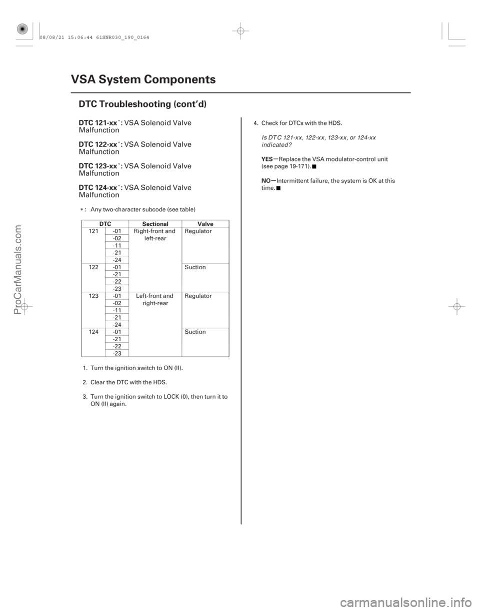
DTC 121-xx :
DTC 122-xx :
DTC 123-xx :
DTC 124-xx :
DTC Sectional Valve YES
NO
19-164VSA System Components
DTC Troubleshooting (cont’d)
VSA Solenoid Valve
Malfunction
VSA Solenoid Valve
Malfunction
VSA Solenoid Valve
Malfunction
VSA Solenoid Valve
Malfunction
: Any two-character subcode (see table)
121 -01 Right-front and left-rearRegulator
-02
-11
-21
-24
122 -01 Suction -21
-22
-23
123 -01 Left-front and right-rearRegulator
-02
-11
-21
-24
124 -01 Suction -21
-22
-23
1. Turn the ignition switch to ON (II).
2. Clear the DTC with the HDS.
3. Turn the ignition switch to LOCK (0), then turn it to ON (II) again. 4. Check for DTCs with the HDS.
Replace the VSA modulator-control unit
(see page 19-171).
Intermittent failure, the system is OK at this
time.
Is DT C 121-xx, 122-xx, 123-xx, or 124-xx indicated?
08/08/21 15:06:44 61SNR030_190_0164
ProCarManuals.com
DYNOMITE -2009-
Page 1657 of 2893
����
�µ
�µ
�µ
�µ �µ
�µ
VSA activation indicator does not go off, and
no DTCs are stored
YES
NO
YES
NO YES
NO
19-165
Symptom Troubleshooting
VSA")
����
�(�#�'���������������
�����������������������)����
�µ
�µ
�µ
�µ �µ
�µ
VSA activation indicator does not go off, and
no DTCs are stored
YES
NO
YES
NO YES
NO
19-165
Symptom Troubleshooting
VSA OFF SWITCH 5P CONNECTOR
BRN1. Turn the ignition switch to ON (II).
2. Check the VSA activation indicator for severalseconds when the ignition switch is turned to
ON (II).
The system is OK at this time.
Go to step 3.
3. Turn the ignition switch to LOCK (0).
4. Disconnect the VSA OFF switch 5P connector (see page 19-170).
5. Check the VSA OFF switch (see page 19-170).
Go to step 6.
ReplacetheVSAOFFswitch(seepage
19-170).
6. Disconnect the gauge control module (tach) 36P connector. 7. Check for continuity between VSA OFF switch 5P
connector terminal No. 2 and body ground.
Repair short to body ground in the wire
between the gauge control module (tach) and the
VSA OFF switch.
Substitute a known-good gauge control
module (tach) (see page 22-277), then go to step 1,
and recheck. If it is OK, replace the original gauge
control module (tach) (see page 22-277).
Wire side of female terminals
Does t he i nd i cat or come on t hen go of f ?
Is the V SA OFF switch OK ? Is there continuity?
08/08/21 15:06:44 61SNR030_190_0165
ProCarManuals.com
DYNOMITE -2009-
Page 1658 of 2893
����
�µ
�µ
�µ
�µ �µ
�µ
�µ
�µ
ABS indicator, brake system indicator, and
VSA indicator do not go off
YES
NO
YES
NO YES
NO
YES
NO
19-")
����
�����
�(�#�'���������������
�����������������������)����
�µ
�µ
�µ
�µ �µ
�µ
�µ
�µ
ABS indicator, brake system indicator, and
VSA indicator do not go off
YES
NO
YES
NO YES
NO
YES
NO
19-166
VSA System Components
Symptom Troubleshooting (cont’d)
VSA MODULATOR-CONTROL UNIT 37P CONNECTOR
IG1 (GRY) VSA MODULATOR-CONTROL UNIT 37P CONNECTOR
IG1 (GRY)
1. Turn the ignition switch to LOCK (0).
2. Check the No. 4 (7.5 A) fuse in the under-dash fuse/relay box.
Go to step 3.
Reinstall the checked fuse, then go to step 9.
3. Disconnect the VSA modulator-control unit 37P connector (see step 2 on page 19- 171).
4. Disconnect the yaw rate-lateral acceleration sensor 5P connector (see page 19- 169).
5. Check for continuity between VSA modulator- control unit 37P connector terminal No. 28 and
body ground.
Repair short to body ground in the wire
between the No. 4 (7.5 A) fuse in the under-dash
fuse/relay box and the VSA modulator-control unit
or the yaw rate-lateral acceleration sensor.
Install a new No. 4 (7.5 A) fuse in the under-
dashfuse/relaybox,thengotostep6. 6. Reconnect all connectors.
7. Turn the ignition switch to ON (II).
8. Check the ABS indicator, the brake system
indicator and the VSA indicator for several seconds
when the ignition switch is tuned to ON (II).
Troubleshooting is complete.
Replace the VSA modulator-control unit
(see page 19-171).
9. Disconnect the VSA modulator-control unit 37P connector (see step 2 on page 19-171).
10. Turn the ignition switch to ON (II).
11. Measure the voltage between VSA modulator- control unit 37P connector terminal No. 28 and
body ground.
Go to step 12.
Repair open in the wire between the No. 4
(7.5 A) fuse in the under-dash fuse/relay box and
the VSA modulator-control unit.
12. Turn the ignition switch to LOCK (0).
Wire side of female terminals Wire side of female terminals
Isthefuseblown?
Is there continuity? Does t he i nd i cat or s come on t hen go of f ?
Is there battery voltage?
08/08/21 15:06:44 61SNR030_190_0166
ProCarManuals.com
DYNOMITE -2009-
Page 1661 of 2893
���� ���
�(�#����������������
�����������������������)���
19-16919-169
Yaw Rate-Lateral Acceleration
Sensor Replacement VSA Sensor Neutral Position")
���
�(�#�'���������������
�������������
�
� �����)���� ���
�(�#�'���������������
�����������������������)���
19-16919-169
Yaw Rate-Lateral Acceleration
Sensor Replacement VSA Sensor Neutral Position
Memorization
AB
9.8 N·m
(1.0 kgf·m, 7.2 lbf·ft) A
NOTE:
Do not damage or drop the sensor as it is sensitive.
Do not use power tools when replacing the sensor.
1. Turn the ignition switch to LOCK (0).
2. Remove the center console (see page 20-92).
3. Remove the yaw rate-lateral acceleration sensor (A) mounting bolts.
4. Pull out the yaw rate-lateral acceleration sensor, then disconnect the sensor connector (B).
5. Install the yaw rate-lateral acceleration sensor in the reverse order of removal.
6. Do the VSA sensor neutral position memorization (see page 19-169). NOTE: Do not press the brake pedal during this
procedure.
1. Park the vehicle on a flat and level surface, with the steering wheel in the straight ahead position.
2. With the ignition switch in LOCK (0), connect the HDS to the data link connector (DLC) (A) under the
driver’s side of the dashboard.
3. Turn the ignition switch to ON (II).
4. Make sure the HDS communicates with the vehicle and the VSA modulator-control unit. If it doesn’t
troubleshoot the DLC circuit (see page 11-204).
5. Select VSA ADJUSTMENT with the HDS, and follow the screen prompts.
NOTE: See the HDS Help menu for specific
instructions.
6. Turn the ignition switch to LOCK (0).
08/08/21 15:06:46 61SNR030_190_0169
ProCarManuals.com
DYNOMITE -2009-
Page 1662 of 2893
���
��������
�(�#�'���������������
���������������
�������)����
�´�µ
19-170 VSA System Components
VSA OFF Switch Test
A
B
VSA OFF SWITCH 5P CONNECTOR GND VSA OFF SW VSA OFF SWITCH 5P CONNECTOR
ILL ( ) ILL ( )
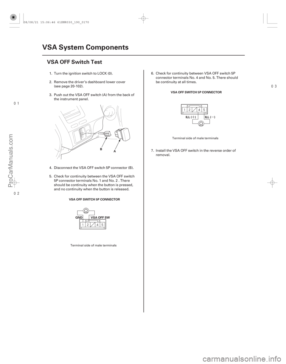
1. Turn the ignition switch to LOCK (0).
2. Remove the driver’s dashboard lower cover(see page 20-102).
3. Push out the VSA OFF switch (A) from the back of the instrument panel.
4. Disconnect the VSA OFF switch 5P connector (B).
5. Check for continuity between the VSA OFF switch 5P connector terminals No. 1 and No. 2 . There
should be continuity when the button is pressed,
and no continuity when the button is released. 6. Check for continuity between VSA OFF switch 5P
connector terminals No. 4 and No. 5. There should
be continuity at all times.
7. Install the VSA OFF switch in the reverse order of removal.
Terminal side of male terminals Terminal side of male terminals
08/08/21 15:06:46 61SNR030_190_0170
ProCarManuals.com
DYNOMITE -2009-