Page 1694 of 2893
����
20-2120-21
Rear Door Latch Replacement
Fastener Locations :Screw,3
A:Screw,1 B
A
A
A
6x1.0mm
6N·m
(0.6 kgf·m, 4 lbf·ft) 6x1.0mm
6N·m
(0.6 kg")
���
�(�#�'�����������
���
���������������
� �����)����
20-2120-21
Rear Door Latch Replacement
Fastener Locations :Screw,3
A:Screw,1 B
A
A
A
6x1.0mm
6N·m
(0.6 kgf·m, 4 lbf·ft) 6x1.0mm
6N·m
(0.6 kgf·m, 4 lbf·ft)C
B
11. Install the handle in the reverse order of removal, and note these items:
Make sure the door locks and opens properly.
When reinstalling the door panel, make sure the
plastic cover is installed properly and sealed
around its outside perimeter to seal out water.
Check for water leaks (see step 9 on page 20-29). NOTE: Put on gloves to protect your hands.
1. Raise the glass fully.
2. Remove the door panel (see page 20-17).
3. Remove the plastic cover, as needed (see step 4 on page 20-19).
4. Remove the screws (A, B) securing the latch (C), then lower it.
5. Detach the rod fastener (see step 6 on page 20-19).
6. Disconnect the outer handle rod from the outer handle (see step 7 on page 20-20).
(cont’d)
08/08/21 14:59:07 61SNR030_200_0023
ProCarManuals.com
DYNOMITE -2009-
Page 1695 of 2893
����
20-2120-21
Rear Door Latch Replacement
Fastener Locations :Screw,3
A:Screw,1 B
A
A
A
6x1.0mm
6N·m
(0.6 kgf·m, 4 lbf·ft) 6x1.0mm
6N·m
(0.6 kg")
���
�(�#�'�����������
���
���������������
� �����)����
20-2120-21
Rear Door Latch Replacement
Fastener Locations :Screw,3
A:Screw,1 B
A
A
A
6x1.0mm
6N·m
(0.6 kgf·m, 4 lbf·ft) 6x1.0mm
6N·m
(0.6 kgf·m, 4 lbf·ft)C
B
11. Install the handle in the reverse order of removal, and note these items:
Make sure the door locks and opens properly.
When reinstalling the door panel, make sure the
plastic cover is installed properly and sealed
around its outside perimeter to seal out water.
Check for water leaks (see step 9 on page 20-29). NOTE: Put on gloves to protect your hands.
1. Raise the glass fully.
2. Remove the door panel (see page 20-17).
3. Remove the plastic cover, as needed (see step 4 on page 20-19).
4. Remove the screws (A, B) securing the latch (C), then lower it.
5. Detach the rod fastener (see step 6 on page 20-19).
6. Disconnect the outer handle rod from the outer handle (see step 7 on page 20-20).
(cont’d)
08/08/21 14:59:07 61SNR030_200_0023
ProCarManuals.com
DYNOMITE -2009-
Page 1696 of 2893
���
��������
20-22Doors
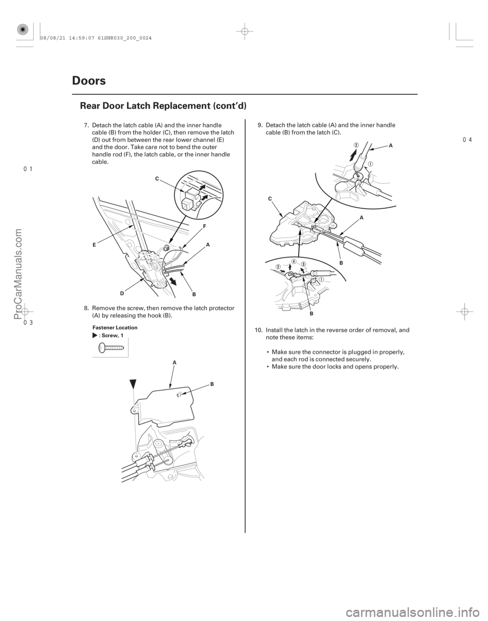
Rear Door Latch Replacement (cont’d)
A
B
C
D F
E
Fastener Location :Screw,1
AB A
A
B
C
B
7. Detach the latch cable (A) and the inner handlecable (B) from the holder (C), then remove the latch
(D) out from between the rear lower channel (E)
and the door. Take care not to bend the outer
handle rod (F), the latch cable, or the inner handle
cable.
8. Remove the screw, then remove the latch protector (A) by releasing the hook (B). 9. Detach the latch cable (A) and the inner handle
cable (B) from the latch (C).
10. Install the latch in the reverse order of removal, and note these items:
Make sure the connector is plugged in properly, and each rod is connected securely.
Make sure the door locks and opens properly.
08/08/21 14:59:07 61SNR030_200_0024
ProCarManuals.com
DYNOMITE -2009-
Page 1697 of 2893
����
20-23
Rear Door Glass and Regulator Replacement
A
B C
FG
H
E
C
E
D
Fastener Locations :Bolt,2
6x1.0mm
9.8 N·m
(1.0 kgf·m,
7.2 lbf·ft")
����
��������
�(�#�'�������������������������������
� �����)����
20-23
Rear Door Glass and Regulator Replacement
A
B C
FG
H
E
C
E
D
Fastener Locations :Bolt,2
6x1.0mm
9.8 N·m
(1.0 kgf·m,
7.2 lbf·ft)A
B
A
C Fastener Locations
:Bolt,1
A:Screw,1 D
4x0.7mm
4N·m
(0.4 kgf·m, 3 lbf·ft)
6x1.0mm
8N·m
(0.8 kgf·m, 6 lbf·ft) A
B C
D
NOTE: Put on gloves to protect your hands.
1. Remove the door panel (see page 20-17).
2. Detach the harness clip (A), and disconnect the power door lock actuator connector (B). Remove
the plug caps (C).
3. Pass the cable (D) and the harnesses (E) through the holes (F) and slit (G) in the plastic cover (H),
then remove it.
4. Carefully move the glass (A) until you can see the bolts, then remove them. Release the glass from
the holder (B), then remove it from the regulator (C),
and carefully lower the glass. Take care not to drop
the glass inside the door. 5. Remove the bolt (A) from the rear lower channel (B).
Pull the glass run channel (C) away as needed, and
remove the screw (D).
(cont’d)
08/08/21 14:59:08 61SNR030_200_0025
ProCarManuals.com
DYNOMITE -2009-
Page 1701 of 2893
����
20-27
Rear Door Weatherstrip Replacement
Fastener Locations:Bolt,1
A :Clip,13
B
B A B
C
D F
E C
E
E
E
8x1.25mm
29 N·m
(3.0 kgf·m, 22 lbf·ft) :")
���
�(�#�'�����������
���
���������������
� �����)����
20-27
Rear Door Weatherstrip Replacement
Fastener Locations:Bolt,1
A :Clip,13
B
B A B
C
D F
E C
E
E
E
8x1.25mm
29 N·m
(3.0 kgf·m, 22 lbf·ft) : Clip, 2
C
:Clip,1
D (White)
(Black) (Left: Yellow
Right: Green)
NOTE:
Put on gloves to protect your hands.
Take care not to scratch the door.
Remove the clips with a clip remover.
1. At the B-pillar, remove the door checker mounting
bolt (A).
2. Detach the clips (B, C, D), then remove the door weatherstrip (E). 3. Install the weatherstrip in the reverse order of
removal, and note these items:
If the clips are damaged or stress-whitened, replace them with new ones.
Make sure the weatherstrip is installed in the holder (F) securely.
Apply medium strength liquid thread lock to the door checker mounting bolt before installation.
When reinstalling the door panel, make sure the
plastic cover is installed properly and sealed
around its outside perimeter to seal out water.
Check for water leaks (see step 9 on page 20-29).
08/08/21 14:59:10 61SNR030_200_0029
ProCarManuals.com
DYNOMITE -2009-
Page 1709 of 2893
����
20-34 Mirrors
Mirror Holder Replacement
A
B C
A
B
C
D E
C
E
F A
B
C B
A B
C
A
C
CB A
A
B
C
NO GOOD
OK
NOTE: Put on gloves to protect yo")
���
��������
�(�#�'�������������������������������
� �����)����
20-34 Mirrors
Mirror Holder Replacement
A
B C
A
B
C
D E
C
E
F A
B
C B
A B
C
A
C
CB A
A
B
C
NO GOOD
OK
NOTE: Put on gloves to protect your hands.
1. Carefully push on the top edge of the mirror holder (A) by hand.
2. Put a shop towel in the opening between the lower edge of the mirror holder and the mirror housing
(B) to prevent scratches, and detach the bottom
clips (C) with a flat-tip screwdriver wrapped with
protective tape.
3. Carefully pull out the bottom edge of the mirror holder (A) to separate the adhesive (B), and then
release the side clips (C).
4. Separate the mirror holder from the actuator (D) by releasing the hooks (E). Disconnect the mirror
defogger connectors (F) from the heater pad
terminals. 5. Before reinstalling the mirror holder to the inner
holder (A) on the actuator, check the actuator rods
(B) and the actuator boots (C). Make sure the
actuator rods are securely mounted in the holes,
and that the boots properly cover each rod.
6. Reconnect the mirror defogger connectors.
7. Reattach the hooks of the mirror holder to the actuator, then position the mirror holder on the
actuator. Carefully push on the clip portions of the
mirror holder until the mirror holder locks into
place.
8. Check the actuator operation.
08/08/21 15:00:05 61SNR030_200_0036
ProCarManuals.com
DYNOMITE -2009-
Page 1742 of 2893
�
�
S
pecial Tools Required
Driver’s side Passenger’s sideFront Door Sill Area
20-66Interior Trim
Trim Removal/Installation - Door Are")
��������
����
�(�#�'��������������������������������� �����)�
�
S
pecial Tools Required
Driver’s side Passenger’s sideFront Door Sill Area
20-66Interior Trim
Trim Removal/Installation - Door Areas
A
B C
D
E
F
G G
A B A
B
G
G
Fastener Locations
:Clip,1
F : Clip, 4
G
(White)
(Orange)
E Fa
stener Locations
: Clip, 1
F : Clip, 4
G
(White)
(Orange)
A
B
C D E
F
G B
A
A
BG
G
G
E
AB
A
A
KTC trim tool set SOJATP2014
NOTE:
Put on gloves to protect your hands.
Take care not to bend or scratch the trim and panels.
Use the appropriate tool from the KTC trim tool set to avoid damage when removing components.
1. Driver’s side: Remove the footrest (see step 3 on page 20-89).
2. Driver’s side: Remove the front side cap from the front door sill trim, and remove the trunk lid/fuel fill
door opener lock cylinder and the screw (see page
20-184).
3. Detach the hooks (A) and the tabs (B) from the kick panel (C) and the B-pillar lower trim (D), and pull
the front door sill trim (E) up by hand to detach the
clips (F, G), then remove it.
4
. Pull out the front door opening seal (A) from thetrim hooks (B) and around the front door opening
flange, then remove the seal.
08/08/21 15:01:29 61SNR030_200_0068
ProCarManuals.com
DYNOMITE -2009-
Page 1773 of 2893
���� ����
�����
�(�#������������������
�����
��������� �����)���
20-9620-96 Consoles
Center Console Armrest
Replacement
Armrest Lock Repla")
���
�����(�#�'�����������������
�����
�����
�
� �����)���� ����
�����
�(�#�'�����������������
�����
��������� �����)���
20-9620-96 Consoles
Center Console Armrest
Replacement
Armrest Lock Replacement
Fastener Locations
:Clip,5
A
A
B CFastener Locations
:TORXScrew,2
A
B
C
Fastener Locations :TORXScrew,2
NOTE: Take care not to scratch the armrest, center
console, and related parts.
1. Remove the center console (see page 20-92).
2. Gently pull out the center console rear cover (A) to detach the clips.
3. Open the armrest (A), pull the pin (B) off the armrest, then separate the armrest and the center
console (C).
4. Install the center console armrest in the reverse order of removal, and if the clips are damaged or
stress-whitened, replace them with new ones. NOTE: Take care not to scratch the armrest and related
parts.
1. Remove the center console armrest (see page 20-96).
2. Remove the screws with a TORX T15 bit. Slide the armrest liner (A) downward to release the hooks (B),
then remove the armrest liner and armrest spring
(C).
3. Remove the screws with a TORX T15 bit.
08/08/21 15:02:50 61SNR030_200_0098
ProCarManuals.com
DYNOMITE -2009-