Page 1254 of 2893
����Standard Thickness
Clutch Discs: 1.94 mm (0.076 in.)
Clutch Plates Standard Thickness:
1st Clutch (wave-plates): 2.0 mm (0.079 in.)
2nd Clutc")
���
�����(�#�'�������
���
�����
�
���
�������
�"�����)����Standard Thickness
Clutch Discs: 1.94 mm (0.076 in.)
Clutch Plates Standard Thickness:
1st Clutch (wave-plates): 2.0 mm (0.079 in.)
2nd Clutch Wave-plates: 2.0 mm (0.079 in.)
Flat-plate: 2.0 mm (0.079 in.)
3rd Clutch Wave-plates: 2.0 mm (0.079 in.) Flat-plates: 2.0 mm (0.079 in.)
4th Clutch (wave-plates): 2.3 mm (0.091 in.)
5th Clutch (wave-plates): 2.3 mm (0.091 in.)
14-330 Shafts and Clutches
Clutch Inspection
A
A
1. Inspect the 4th and 5th clutch pistons and the clutch piston check valves (A).
2. If the clutch piston check valve is loose or damaged, replace the clutch piston.
3. Check the spring retainer for wear and damage.
4. Check the oil seal (A) on the spring retainer of the 1st, 2nd, and 3rd clutches for wear, damage, and
peeling.
5. If the oil seal is worn, damaged, or peeling, replace the spring retainer. 6. Inspect the clutch discs, the clutch plates, and the
clutch end-plate for wear, damage, and
discoloration.
7. If the clutch discs are worn or damaged, replace them as a set. If the clutch discs are replaced,
inspect the clearance between the clutch end-plate
andthetopdisc.
8. If any plate is worn, damaged, or discolored, replace the damaged plate with a new plate, and
inspect the other wave-plates for a phase
difference. If the clutch plate is replaced, inspect
the clearance between the clutch end-plate and the
top disc.
9. If the clutch end-plate is worn, damaged, or discolored, inspect the clearance between the
clutch end-plate and the top disc, then replace the
clutch end-plate.
08/08/21 14:52:19 61SNR030_140_0332
ProCarManuals.com
DYNOMITE -2009-
Page 1260 of 2893
����
���� ����
����
14-336Shafts and Clutches
1st, 2nd, and 3rd Clutch Reassembly (cont’d)
07LAE-PX40000
AB
C A
B
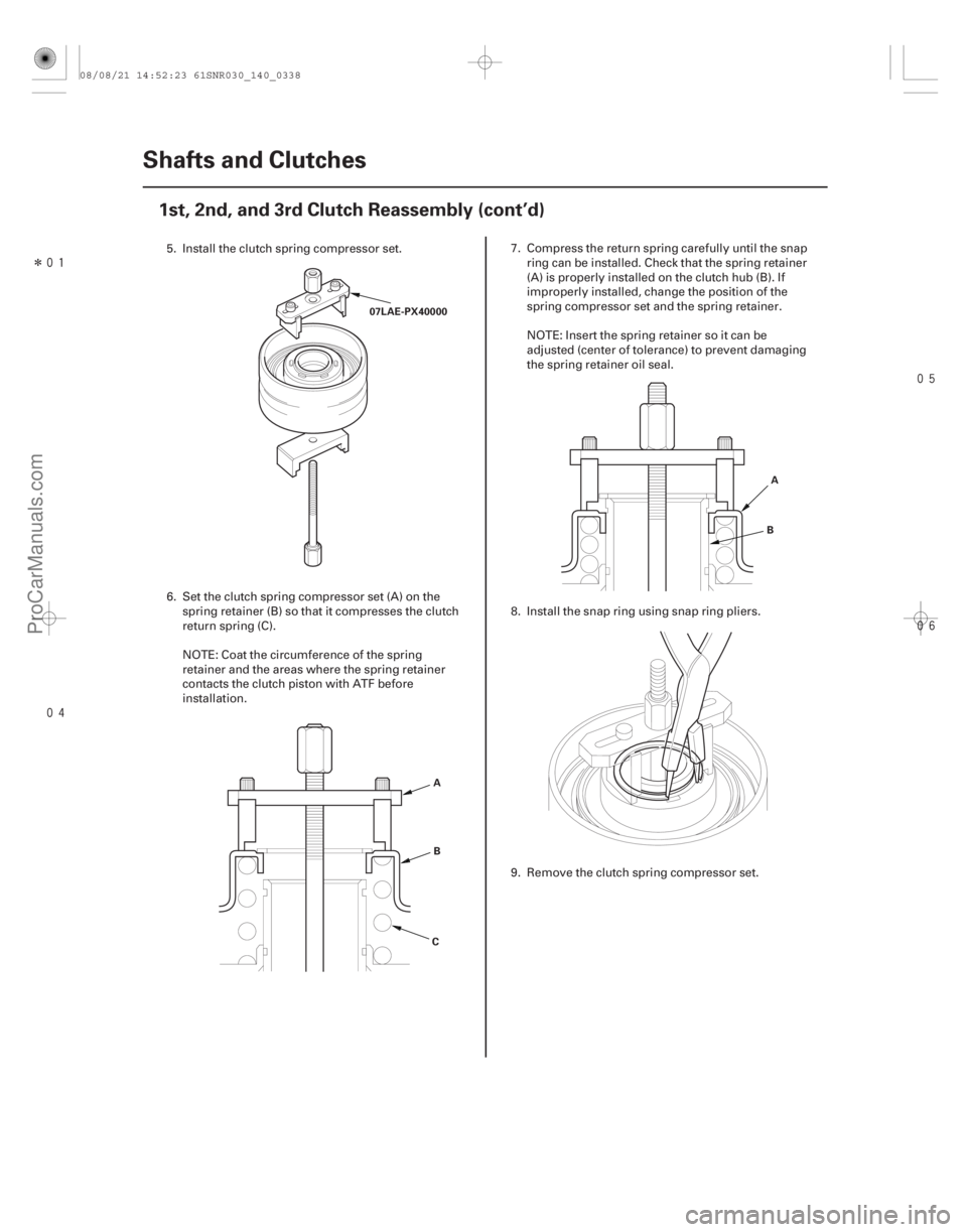
5. Install the clutch spring compressor set.
6. Set the clutch spring compressor set (A) on the spring retainer (B) so that it compresses the clutch
return spring (C).
NOTE: Coat the circumference of the spring
retainer and the areas where the spring retainer
contacts the clutch piston with ATF before
installation. 7. Compress the return spring carefully until the snap
ring can be installed. Check that the spring retainer
(A) is properly installed on the clutch hub (B). If
improperly installed, change the position of the
spring compressor set and the spring retainer.
NOTE: Insert the spring retainer so it can be
adjusted (center of tolerance) to prevent damaging
the spring retainer oil seal.
8. Install the snap ring using snap ring pliers.
9. Remove the clutch spring compressor set.
08/08/21 14:52:23 61SNR030_140_0338
ProCarManuals.com
DYNOMITE -2009-
Page 1261 of 2893
�������
����
14-337
Improperly installed:
Properly installed:
A B
B
A A
B
CD
E
A
B G
E
D
C F
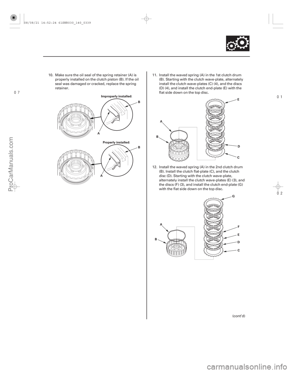
10. Make sure the oil seal of the spring retainer (A) is
properly installed on the clutch piston (B). If the oil
seal was damaged or cracked, replace the spring
retainer. 11. Install the waved spring (A) in the 1st clutch drum
(B). Starting with the clutch wave-plate, alternately
install the clutch wave-plates (C) (4), and the discs
(D) (4), and install the clutch end-plate (E) with the
flat side down on the top disc.
12. Install the waved spring (A) in the 2nd clutch drum (B). Install the clutch flat-plate (C), and the clutch
disc (D). Starting with the clutch wave-plate,
alternately install the clutch wave-plates (E) (3), and
the discs (F) (3), and install the clutch end-plate (G)
with the flat side down on the top disc.
(cont’d)
08/08/21 14:52:24 61SNR030_140_0339
ProCarManuals.com
DYNOMITE -2009-
Page 1283 of 2893
���
�������
����
�(�#�'�������
���
�����
�
���
�������
� �����)����
Special Tools Required
14-358
A/T Differential
Oil Seal Replacement
07749-0010000
07947-SD90101
A
07749-0010000
07JAD-PH80101
A
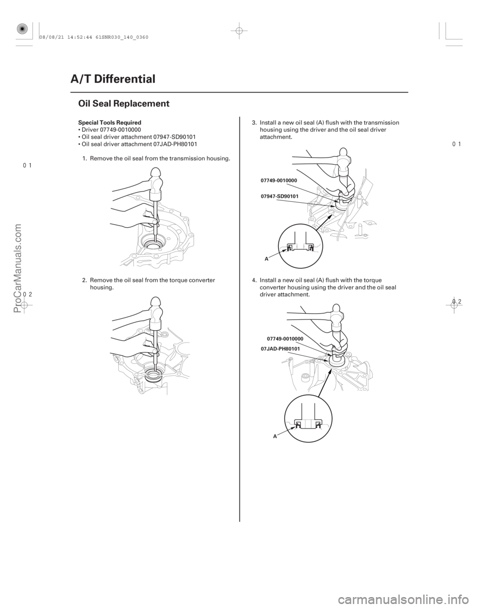
Driver 07749-0010000
Oil seal driver attachment 07947-SD90101
Oil seal driver attachment 07JAD-PH801011. Remove the oil seal from the transmission housing.
2. Remove the oil seal from the torque converter housing. 3. Install a new oil seal (A) flush with the transmission
housing using the driver and the oil seal driver
attachment.
4. Install a new oil seal (A) flush with the torque converter housing using the driver and the oil seal
driver attachment.
08/08/21 14:52:44 61SNR030_140_0360
ProCarManuals.com
DYNOMITE -2009-
Page 1294 of 2893
���
���
���
���
���
���
���
���
�(�#�'�������������������������
�����
�%�����)����Ref. No. Tool Number Description Qty
16-2
Driveline/Axle
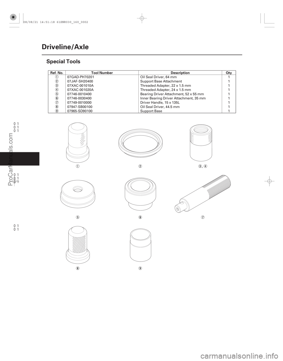
Special Tools
07GAD-PH70201
Oil Seal Driver, 64 mm 1
07JAF-SH20400 Support Base Attachment 1
07XAC-001010A Threaded Adapter, 22 x 1.5 mm 1
07XAC-001020A Threaded Adapter, 24 x 1.5 mm 1
07746-0010400 Bearing Driver Attachment, 52 x 55 mm 1
07746-0030400 Inner Bearing Driver Attachment, 35 mm 1
07749-0010000 Driver Handle, 15 x 135L 1
07947-SB00100 Oil Seal Driver, 44.5 mm 1
07965-SD90100 Support Base 1
,
08/08/21 14:51:18 61SNR030_160_0002
ProCarManuals.com
DYNOMITE -2009-
Page 1297 of 2893
����
��������
����
16-5
A
B
A
B
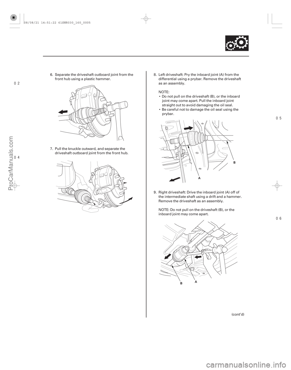
6. Separate the driveshaft outboard joint from the
front hub using a plastic hammer.
7. Pull the knuckle outward, and separate the driveshaft outboard joint from the front hub. 8. Left driveshaft: Pry the inboard joint (A) from the
differential using a prybar. Remove the driveshaft
as an assembly.
NOTE: Do not pull on the driveshaft (B), or the inboard joint may come apart. Pull the inboard joint
straight out to avoid damaging the oil seal.
Be careful not to damage the oil seal using the prybar.
9. Right driveshaft: Drive the inboard joint (A) off of the intermediate shaft using a drift and a hammer.
Remove the driveshaft as an assembly.
NOTE: Do not pull on the driveshaft (B), or the
inboard joint may come apart.
(cont’d)
08/08/21 14:51:22 61SNR030_160_0005
ProCarManuals.com
DYNOMITE -2009-
Page 1314 of 2893

C
12x1.25mm
59 N·m
(6.0 kgf·m,
43 lbf·ft)
D
12x1.25mm
59 N·m
(6.0 kgf·m,
43 lbf·ft)
A
B
5. Clean the areas")
���������
����
16-21
E
D A E
D
A
C B B
A
E
12x1.25mm
59 N·m
(6.0 kgf·m,
43 lbf·ft)
C
12x1.25mm
59 N·m
(6.0 kgf·m,
43 lbf·ft)
D
12x1.25mm
59 N·m
(6.0 kgf·m,
43 lbf·ft)
A
B
5. Clean the areas where the driveshaft contacts the
differential thoroughly with solvent or brake
cleaner, and dry with compressed air.
NOTE: Do not wash the rubber parts with solvent.
6. Insert the inboard end (A) of the driveshaft into the differential (B) or the intermediate shaft (C) until the
set ring (D) locks in the groove (E).
NOTE: Insert the driveshaft horizontally to prevent
damaging the oil seal. 7. Install the outboard joint (A) into the front hub (B).
8. Connect the knuckle (A) onto the lower arm (B).
During installation, install a new flange bolt and
new self-locking nuts. After lightly tightening all
three fasteners, tighten them to the specified
torque in the following order: the nut on the front
(C), the nut on the rear (D), then the bolt (E).
(cont’d)
Replace.
Replace.
Replace.
08/08/21 14:51:44 61SNR030_160_0021
ProCarManuals.com
DYNOMITE -2009-
Page 1315 of 2893

B
A
K20Z2 engine model:
22x1.5mm
181 N·m
(18.5 kgf·m, 134 lbf·ft)
K20Z3 engine model:
24x1.5mm
245 N·m
(25.0 kgf·m, 180 lbf·ft)
9.")
�����
16-22Driveline/Axle
Driveshaft Installation (cont’d)
B
A
K20Z2 engine model:
22x1.5mm
181 N·m
(18.5 kgf·m, 134 lbf·ft)
K20Z3 engine model:
24x1.5mm
245 N·m
(25.0 kgf·m, 180 lbf·ft)
9. Apply small amount of engine oil to the seating surface of new spindle nut (A).
10. Install the spindle nut, then tighten it. After tightening, use a drift to stake the spindle nut
shoulder (B) against the driveshaft.
11. Clean the mating surfaces of the brake disc and the wheel, then install the front wheels.
12. Turn the front wheel by hand, and make sure there is no interference between the driveshaft and
surrounding parts. 13. Refill the transmission with the recommended
transmission fluid:
5-speed manual transmission (see page 13-5)
6-speed manual transmission (see page 13-82)
Automatic transmission (see page 14-232)
14. Lower the vehicle on the lift.
15. Check the wheel alignment, and adjust it if necessary (see page 18-5).
16. Test-drive the vehicle.
Replace.
Replace.
08/08/21 14:51:45 61SNR030_160_0022
ProCarManuals.com
DYNOMITE -2009-