Page 1182 of 2893
: 6.1 6.2 mm (0.240 0.244 in.)
End Gap (C): 1.8 2.0 mm (0.07 0.08 in.)
14-266A/T Gear Position")
����
����� ����
�µ
�µ�µ
�µ�µ
Transmission Range Switch Connector Selector Control Shaft:
Width (B): 6.1 6.2 mm (0.240 0.244 in.)
End Gap (C): 1.8 2.0 mm (0.07 0.08 in.)
14-266A/T Gear Position Indicator
Transmission Range Switch Test (cont’d)
Connector Terminal/Signal
25
134
687910
P
R
N
D
S
Posi-
tion A
C
B
ATP
NP ATP
FWD
GND
ATP
RVS ATP
N ATP
S ATP
PATP
R ATP
D
7. Disconnect the transmission range switch
connector.
8. Check for continuity between the terminals at the switch connector. There should be continuity
between the terminals in the following table for
each switch position.
9. If the transmission range switch test is OK, replace the faulty transmission range switch harness, then
go to step 12. If there is no continuity between any
terminals, go to step 10. 10. Remove the transmission range switch, and check
the end of the selector control shaft (A).
11. If the measurement at the end of the selector control shaft is within the standard, replace the
transmission range switch. If the measurement is
out of the standard, repair the selector control shaft
end, and recheck the transmission range switch
continuity.
12. Check the connector for rust, dirt, or oil, clean or repair if necessary, then connect the connector
securely.
13. Install the removed parts in the reverse order of removal.
08/08/21 14:49:01 61SNR030_140_0268
ProCarManuals.com
DYNOMITE -2009-
Page 1184 of 2893

A
C
B
6x1.0mm
12 N·m (1.2 kgf·m, 8.7 lbf·ft) 6x1.0mm
12 N·m (1.2 kgf·m, 8.7 lbf·ft)A
7. Install t")
����
��������
14-268A/T Gear Position Indicator
Transmission Range Switch Replacement (cont’d)
A
C
B
6x1.0mm
12 N·m (1.2 kgf·m, 8.7 lbf·ft) 6x1.0mm
12 N·m (1.2 kgf·m, 8.7 lbf·ft)A
7. Install the transmission range switch (A) gently on
the selector control shaft (B) while holding it in the
N position with the 2.0 mm (0.08 in.) blade (C).
8. Tighten the bolts on the transmission range switch while you continue to holding the N position. Do
not move the transmission range switch when
tightening the bolts. Remove the feeler gauge. 9. Check the connectors for rust, dirt, or oil, clean or
repair if necessary, then connect the connector
securely.
10. Turn the ignition switch to ON (II). Move the shift lever through all positions, and check the
transmission range switch synchronization with the
A/T gear position indicator.
11. Check that the engine will start with the shift lever in P and N, and will not start in any other shift lever
position.
12. Check that the back-up lights come on when the shift lever is in R.
13. Allow the front wheels to rotate freely, then start the engine, and check the shift lever operation.
14. Install the transmission range switch cover (A).
08/08/21 14:49:03 61SNR030_140_0270
ProCarManuals.com
DYNOMITE -2009-
Page 1212 of 2893
���
����
�(�#�'�������
���
�����
�����
��������� �����)���� ���
����
�(�#�'�������
���
�����
�����
��������� �����)����
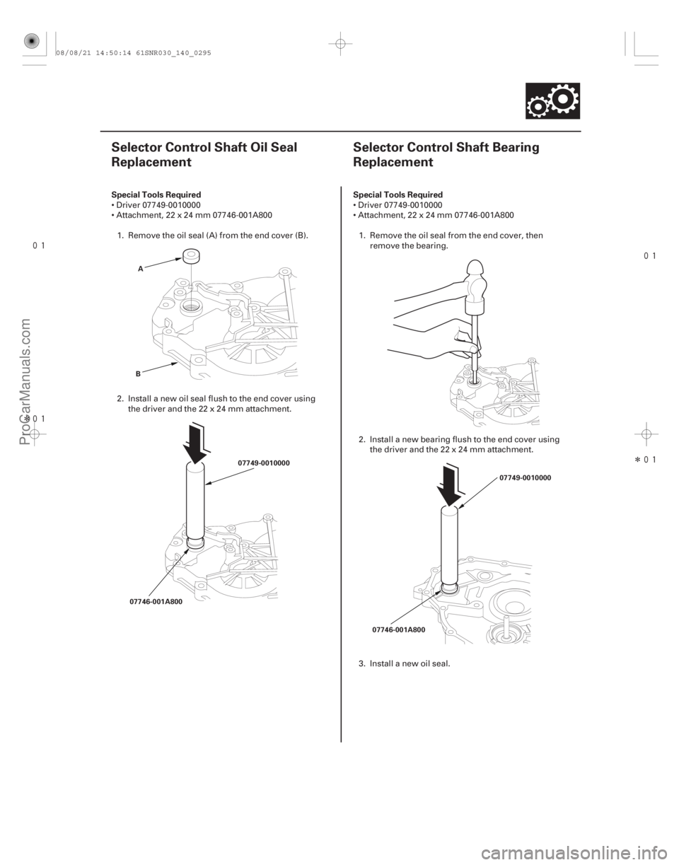
Special Tools Required Special Tools Required
14-29314-293
Selector Control Shaft Oil Seal
Replacement
Selector Control Shaft Bearing
Replacement
A
B 07749-0010000
07746-001A800 07746-001A80007749-0010000
Driver 07749-0010000
Attachment, 22 x 24 mm 07746-001A800
1. Remove the oil seal (A) from the end cover (B).
2. Install a new oil seal flush to the end cover using thedriverandthe22x24mmattachment. Driver 07749-0010000
Attachment, 22 x 24 mm 07746-001A800
1. Remove the oil seal from the end cover, then remove the bearing.
2. Install a new bearing flush to the end cover using thedriverandthe22x24mmattachment.
3. Install a new oil seal.
08/08/21 14:50:14 61SNR030_140_0295
ProCarManuals.com
DYNOMITE -2009-
Page 1225 of 2893
���� SPRING SPECIFICATIONS Springs Standard (New)-Unit: mm (in.) Wire Diameter O.D. Free Length No. of Coils
14-303
Main Valve Body Disassembly, Inspe")
���
�(�#�'�������
���
���������
���������
�"�����)���� SPRING SPECIFICATIONS Springs Standard (New)-Unit: mm (in.) Wire Diameter O.D. Free Length No. of Coils
14-303
Main Valve Body Disassembly, Inspection, and Reassembly
ASPRING SEAT
BC RELIEF VALVE
D VALVE SLEEVE
MAIN VALVE BODY CHECK BALLCOOLER CHECK
VALVEFE
LOCK-UP
CONTROL
VALVE
SHIFT VALVE E SHIFT VALVE A
SHIFT VALVE B
SHIFT VALVE C
CHECK BALL
ROLLER
SERVO CONTROL VALVE
MANUAL VALVE
VALVE CAP VALVE CAP CLIP G
H
1. Clean all parts thoroughly in solvent, and dry them with compressed air. Blow out all passages.
2. Do not use a magnet to remove the check balls, it may magnetize the balls.
3. Inspect the valve body for scoring and damage.
4. Check all valves for free movement. If any fail to slide freely, do the valve body repair procedure (see page 14-301).
5. Coat all parts with ATF during assembly.
A Shift valve A spring 0.8 (0.031) 5.6 (0.220) 28.1 (1.106) 15.9B Shift valve B spring 0.8 (0.031) 5.6 (0.220) 28.1 (1.106) 15.9
C Shift valve C spring 0.8 (0.031) 5.6 (0.220) 28.1 (1.106) 15.9
D Relief valve spring 1.0 (0.039) 9.6 (0.378) 34.1 (1.343) 10.2 E Lock-up control valve spring 0.65 (0.026) 7.1 (0.280) 23.1 (0.909) 12.7F Cooler check valve spring 0.85 (0.033) 6.6 (0.260) 27.0 (1.063) 11.3
G Servo control valve spring 0.7 (0.028) 6.6 (0.260) 35.7 (1.406) 17.2 H Shift valve E spring 0.8 (0.031) 5.6 (0.220) 28.1 (1.106) 15.9
08/08/21 14:51:13 61SNR030_140_0305
ProCarManuals.com
DYNOMITE -2009-
Page 1227 of 2893
���� SPRING SPECIFICATIONSSprings Standard (New)-Unit: mm (in.) Wire Diameter O.D. Free Length No. of Coils
14-305
Regulator Valve Body Disassembly")
����
�(�#�'�������
���
���������
���������
�"�����)���� SPRING SPECIFICATIONSSprings Standard (New)-Unit: mm (in.) Wire Diameter O.D. Free Length No. of Coils
14-305
Regulator Valve Body Disassembly, Inspection, and Reassembly
6x1.0mm
12 N·m (1.2 kgf·m, 8.7 lbf·ft)
F G
H 1ST ACCUMULATOR
PISTON
O-RING
REGULATOR VALVE BODY
LOCK-UP SHIFT VALVE
E
VALVE CAP CLIP
VALVE CAP REGULATOR VALVE
TORQUE CONVERTER
CHECK VALVE D
SPRING SEAT A
B
C ACCUMULATOR COVER
3RD ACCUMULATOR PISTON
REGULATOR
SPRING CAP
STOP BOLT
6x1.0mm
12 N·m (1.2 kgf·m,
8.7 lbf·ft) BAFFLE PLATE
1. Clean all parts thoroughly in solvent, and dry them with compressed air. Blow out all passages.
2. Inspect the valve body for scoring and damage.
3. Check all valves for free movement. If any fail to slide freely, do the valve body repair procedure (see page 14-301).
4. Hold the regulator spring cap in place while removing the stop bolt. The regulator spring cap is spring loaded.
5. Coat all parts with ATF during assembly.
6. Replace the O-rings with new ones.
7. When reassembling the valve body, align the hole in the regulator spring cap with the hole in the valve body, then
press the spring cap into the valve body, and tighten the stop bolt.
A Stator reaction spring 4.5 (0.177) 35.4 (1.394) 30.3 (1.193) 1.92 B Regulator valve spring A 1.9 (0.075) 14.7 (0.579) 80.6 (3.173) 16.1
C Regulator valve spring B 1.6 (0.063) 9.2 (0.362) 44.0 (1.732) 12.5
D Torque converter check valve spring 1.2 (0.047) 8.6 (0.339) 33.8 (1.331) 12.2 E Lock-up shift valve spring 1.0 (0.039) 6.6 (0.260) 35.5 (1.398) 18.2F 3rd accumulator spring 2.5 (0.098) 14.6 (0.575) 29.9 (1.177) 4.9
G 1st accumulator spring A 2.4 (0.094) 18.6 (0.732) 49.0 (1.929) 7.1 H 1st accumulator spring B 2.3 (0.091) 12.2 (0.480) 31.5 (1.240) 6.6
Replace.
08/08/21 14:51:14 61SNR030_140_0307
ProCarManuals.com
DYNOMITE -2009-
Page 1228 of 2893
���� SPRING SPECIFICATIONS Springs Standard (New)-Unit: mm (in.) Wire Diameter O.D. Free Length No. of Coils
14-306Valve Body
Servo Body Disassembly,")
���
�(�#�'�������
���
���������
���������
�"�����)���� SPRING SPECIFICATIONS Springs Standard (New)-Unit: mm (in.) Wire Diameter O.D. Free Length No. of Coils
14-306Valve Body
Servo Body Disassembly, Inspection, and Reassembly
6x1.0mm
12 N·m (1.2 kgf·m, 8.7 lbf·ft)
O-RING
SERVO VALVE/SHIFT FORK SHAFT
SPRING SEAT ACCUMULATOR COVER
F
5TH ACCUMULATOR PISTON
SERVO BODY
O-RING
SHIFT VALVE D
A
O-RING
4TH ACCUMULATOR PISTON
O-RING
B
C
2ND ACCUMULATOR PISTON
DE
1. Clean all parts thoroughly in solvent, and dry them with compressed air. Blow out all passages.
2. Inspect the valve body for scoring and damage.
3. Check shift valve D for free movement. If any fail to slide freely, do the valve body repair procedure (see page
14-301).
4. When removing and installing the shift solenoid valves, refer to the shift solenoid valves removal and installation (see page 14-307).
5. Coat all parts with ATF during assembly.
6. Replace the O-rings with new ones.
A Shift valve D spring 0.8 (0.031) 5.6 (0.220) 28.1 (1.106) 15.9B 4th accumulator spring B 2.3 (0.091) 12.2 (0.480) 31.5 (1.240) 6.6
C 4th accumulator spring A 2.4 (0.094) 18.6 (0.732) 49.0 (1.929) 7.1
D 2nd accumulator spring B 2.0 (0.079) 10.6 (0.417) 34.0 (1.339) 8.0 E 2nd accumulator spring A 2.2 (0.087) 16.6 (0.654) 48.2 (1.898) 8.5F 5th accumulator spring 2.5 (0.098) 14.6 (0.575) 29.9 (1.177) 4.9
Replace.
Replace.
Replace.
Replace.
08/08/21 14:51:14 61SNR030_140_0308
ProCarManuals.com
DYNOMITE -2009-
Page 1230 of 2893
����
Special Tools Required
14-308
Torque Converter Housing
Mainshaft Bearing and Oil Seal Replacement
07736-A01000B or
07736-A01000A
A")
�µ
���
���� ����
�(�#�'�������
���
�����
�
�����������
� �����)����
Special Tools Required
14-308
Torque Converter Housing
Mainshaft Bearing and Oil Seal Replacement
07736-A01000B or
07736-A01000A
A
07749-001000007746-0010500 07749-0010000
07746-0010600
Adjustable bearing puller, 25 40 mm07736-A01000B or 07736-A01000A
Driver 07749-0010000
Attachment, 62 x 68 mm 07746-0010500
Attachment, 72 x 75 mm 07746-0010600
1. Remove the mainshaft bearing and the oil seal using the adjustable bearing puller and a
commercially available 3/8 ’’-16 slide hammer (A).
2. Install a new mainshaft bearing until it bottoms in the housing using the driver and the 62 x 68 mm
attachment. 3. Install a new oil seal flush using the housing using
thedriverandthe72x75mmattachment.
NOTE: Do not drive the seal into the torque
converter housing until it bottoms out; it will block
the fluid return passage and cause transmission
damage.
08/08/21 14:51:16 61SNR030_140_0310
ProCarManuals.com
DYNOMITE -2009-
Page 1233 of 2893
�µ
�µ
���
����
�(�#�'�������
���
�����
�����
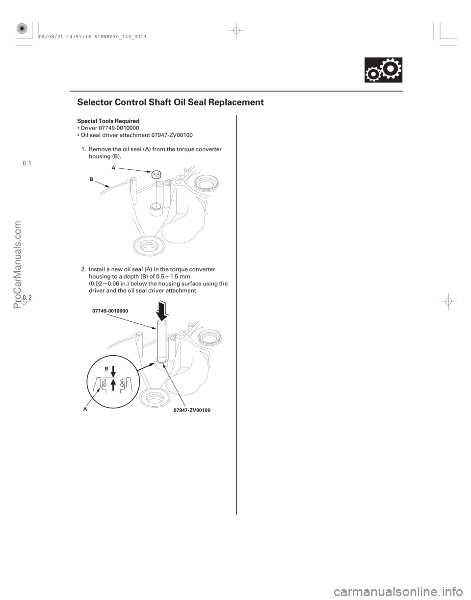
��������� �����)���� Special Tools Required
14-311
Selector Control Shaft Oil Seal Replacement
A
B
07749-0010000 07947-ZV00100
A B
Driver 07749-0010000
Oil seal driver attachment 07947-ZV00100
1. Remove the oil seal (A) from the torque converter housing (B).
2. Install a new oil seal (A) in the torque converter housing to a depth (B) of 0.5 1.5 mm
(0.02 0.06 in.) below the housing surface using the
driver and the oil seal driver attachment.
08/08/21 14:51:18 61SNR030_140_0313
ProCarManuals.com
DYNOMITE -2009-